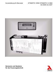
Quick Reference for End-Users CarboSen1000 Sensors ... - lamtec
Quick Reference for End-Users CarboSen1000 Sensors ... - lamtec
Quick Reference for End-Users CarboSen1000 Sensors ... - lamtec
- No tags were found...

Create successful ePaper yourself
Turn your PDF publications into a flip-book with our unique Google optimized e-Paper software.
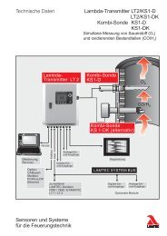
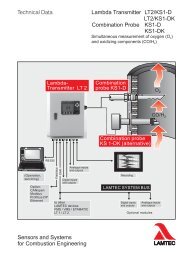
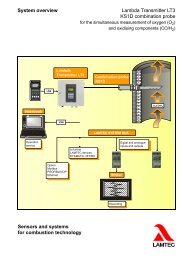
4 Installation and Commissioning4.3 Installations InstructionsIf the electronics are connected to the attached sensor, the saved resistance R ki in the memorywould be drawn up <strong>for</strong> heating control. The cold start phase takes approx. 30s. During theoperation, this resistance would be monitored. Furthermore, the heating resistance of theheater would be verified permanently. If this exceeds 35, a circuit failure would be assumedand a failure message would be shown.Fig. 4-1 X164 with connection diagram4.3.1 CarboSen ST and in Clip- and Rod HousingNo. General terms Assignments1 Power supply PE2 0V3 24V DC4 Analogue output 1 Screen5 Minus6 Plus7 Analogue output 2 Screen8(only with 2-board type)Minus9 Plus10 LAMTEC SYSTEM BUS Screen11 CAN-High12 CAN-Low13 CAN-GNDDrill a bore hole (the size of the bore hole depends on the size of the sensor bracket) on theflue gas duct and attach the sensor bracket to the flue gas duct.For a better flow of the housing, older versions as well as special versions should have twobore holes, which are opposite each other and with a flow direction of 90°C as possible.Fig. 4-2 <strong>CarboSen1000</strong>ST14