

DeviceNet Programmers Guide - Copley Controls
DeviceNet Programmers Guide - Copley Controls
DeviceNet Programmers Guide - Copley Controls
- No tags were found...

You also want an ePaper? Increase the reach of your titles
YUMPU automatically turns print PDFs into web optimized ePapers that Google loves.
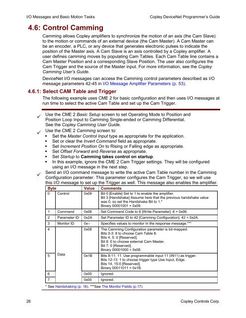
I/O Messages and Basic Motion Tasks4.6: Control Camming<strong>Copley</strong> <strong>DeviceNet</strong> Programmer’s <strong>Guide</strong>Camming allows <strong>Copley</strong> amplifiers to synchronize the motion of an axis (the Cam Slave)to the motion or commands of an external device (the Cam Master). A Cam Master canbe an encoder, a PLC, or any device that generates electronic pulses to indicate theposition of the Master axis. A Cam Slave is an axis controlled by a <strong>Copley</strong> amplifier. Auser defines camming moves by populating Cam Tables. Each Cam Table line contains aCam Master Position and a corresponding Slave Position. The user also configures theCam Trigger and the source of the Master input. For more information, see the <strong>Copley</strong>Camming User’s <strong>Guide</strong>.<strong>DeviceNet</strong> I/O messages can access the Camming control parameters described as I/Omessage parameters 42-45 in I/O Message Amplifier Parameters (p. 53).4.6.1: Select CAM Table and TriggerThe following example uses CME 2 for basic configuration and then uses I/O messages atrun time to select the active Cam Table and set up the Cam Trigger.Use the CME 2 Basic Setup screen to set Operating Mode to Position andPosition Loop Input to Camming Single-ended or Camming Differential.See the <strong>Copley</strong> Camming User <strong>Guide</strong>.Use the CME 2 Camming screen to: Set the Master Control Input type as appropriate for the application. Set or clear the Invert Command field as appropriate. Set Increment Position On to Rising or Falling edge as appropriate. Set Offset Forward and Reverse as appropriate. Set Startup to Camming takes control on startup. In this example, ignore the CME 2 Cam Trigger settings. They will be configuredusing an I/O message in the next step.Send an I/O command message to write the active Cam Table number in the CammingConfiguration parameter. This parameter configures the Cam Trigger, so we will usethis I/O message to set up the Trigger as well. This message also enables the amplifier.Byte Value Comments0 Control 0x09 Bit 0 [Enable] Set to 1 to enable the amplifier.Bit 3 [Handshake] Assume here that the previous handshake valuewas 0, so set the Handshake Bit to 1.*Binary 00001001 = 0x09.1 Command 0x06 Set Command Code to 6 [Write Parameter]. 6 = 0x06.2 Parameter ID 0x2A Set Parameter ID to 42 [Camming Configuration]. 42 = 0x2A.3 Monitor ID 0x-- Specifies values to monitor in the response message.***4 0x08 The Camming Configuration parameter is bit-mapped:Bits 0-3: 8 to choose Cam Table 8.Bits 4, 5: 0 [Reserved].Bit 6: 0 to choose external Cam Master.Bit 7: 0 [Reserved].Binary 00001000 = 0x08.5 Data0x1B Bits 8-11: 11. Use programmable input 11 (IN11) as trigger.Bits 12-13: 1 to choose trigger type Use Input, Edge.Bits 14, 15:0 [Reserved].Binary 00011011 = 0x1B.6 0x00 Ignored.70x00 Ignored.* See Handshaking (p. 16). ***See The Monitor Fields (p.17).26 <strong>Copley</strong> <strong>Controls</strong> Corp.


