

DeviceNet Programmers Guide - Copley Controls
DeviceNet Programmers Guide - Copley Controls
DeviceNet Programmers Guide - Copley Controls
- No tags were found...

Create successful ePaper yourself
Turn your PDF publications into a flip-book with our unique Google optimized e-Paper software.
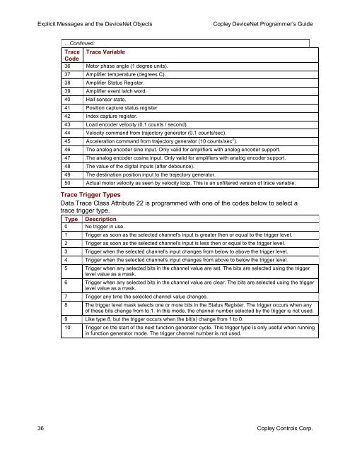
Explicit Messages and the <strong>DeviceNet</strong> Objects<strong>Copley</strong> <strong>DeviceNet</strong> Programmer’s <strong>Guide</strong>…Continued:Trace Trace VariableCode36 Motor phase angle (1 degree units).37 Amplifier temperature (degrees C).38 Amplifier Status Register.39 Amplifier event latch word.40 Hall sensor state.41 Position capture status register42 Index capture register.43 Load encoder velocity (0.1 counts / second).44 Velocity command from trajectory generator (0.1 counts/sec).45 Acceleration command from trajectory generator (10 counts/sec 2 ).46 The analog encoder sine input. Only valid for amplifiers with analog encoder support.47 The analog encoder cosine input. Only valid for amplifiers with analog encoder support.48 The value of the digital inputs (after debounce).49 The destination position input to the trajectory generator.50 Actual motor velocity as seen by velocity loop. This is an unfiltered version of trace variable.Trace Trigger TypesData Trace Class Attribute 22 is programmed with one of the codes below to select atrace trigger type.Type Description0 No trigger in use.1 Trigger as soon as the selected channel's input is greater then or equal to the trigger level.2 Trigger as soon as the selected channel's input is less then or equal to the trigger level.3 Trigger when the selected channel's input changes from below to above the trigger level.4 Trigger when the selected channel's input changes from above to below the trigger level.5 Trigger when any selected bits in the channel value are set. The bits are selected using the triggerlevel value as a mask.6 Trigger when any selected bits in the channel value are clear. The bits are selected using the triggerlevel value as a mask.7 Trigger any time the selected channel value changes.8 The trigger level mask selects one or more bits in the Status Register. The trigger occurs when anyof these bits change from to 1. In this mode, the channel number selected by the trigger is not used.9 Like type 8, but the trigger occurs when the bit(s) change from 1 to 0.10 Trigger on the start of the next function generator cycle. This trigger type is only useful when runningin function generator mode. The trigger channel number is not used.36 <strong>Copley</strong> <strong>Controls</strong> Corp.


