

DeviceNet Programmers Guide - Copley Controls
DeviceNet Programmers Guide - Copley Controls
DeviceNet Programmers Guide - Copley Controls
- No tags were found...

You also want an ePaper? Increase the reach of your titles
YUMPU automatically turns print PDFs into web optimized ePapers that Google loves.
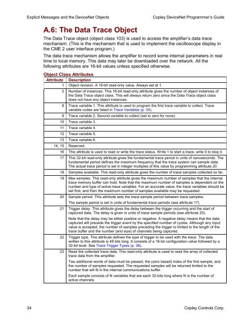
Explicit Messages and the <strong>DeviceNet</strong> Objects<strong>Copley</strong> <strong>DeviceNet</strong> Programmer’s <strong>Guide</strong>A.6: The Data Trace ObjectThe Data Trace object (object class 103) is used to access the amplifier’s data tracemechanism. (This is the mechanism that is used to implement the oscilloscope display inthe CME 2 user interface program.)The data trace mechanism allows the amplifier to record some internal parameters in realtime to local memory. This data may later be downloaded over the network. All thefollowing attributes are 16-bit values unless specified otherwise.Object Class AttributesAttribute Description1 Object revision. A 16-bit read-only value. Always set at 1.2 Number of instances. This 16-bit read-only attribute gives the number of object instances ofthe Data Trace object class. This will always return zero since the Data Trace object classdoes not have any object instances.8 Trace variable 1. This attribute is used to program the first trace variable to collect. Tracevariable codes are listed in Trace Variables (p. 35).9 Trace variable 2. Second variable to collect (set to zero for none).10 Trace variable 3.11 Trace variable 4.12 Trace variable 5.13 Trace variable 6.14, 15 Reserved.16 This attribute is used to read or write the trace status. Write 1 to start a trace, write 0 to stop it.17 This 32-bit read-only attribute gives the fundamental trace period in units of nanoseconds. Thefundamental period defines the maximum frequency that the trace system can sample data.The actual trace period is set in integer multiples of this value by programming attribute 20.18 Samples available. This read-only attribute gives the number of trace samples collected so far.19 Max samples. This read-only attribute gives the maximum number of samples that the internaltrace memory buffer can hold. Note that the maximum number of samples is dependent on thenumber and type of active trace variables. For an accurate value, the trace variables should beset first, and then the maximum number of samples available may be requested.20 Sample period. This attribute sets the trace sample period between trace samples.The sample period is set in units of fundamental trace periods (see attribute 17).21 Trigger delay. This attribute gives the delay between the trigger occurring and the start ofcaptured data. The delay is given in units of trace sample periods (see attribute 20).Note that the delay may be either positive or negative. A negative delay means that the datacaptured will precede the trigger event by the specified number of cycles. Although any inputvalue is accepted, the number of samples preceding the trigger is limited to the length of thetrace buffer and the number (and size) of channels being captured.22 Trigger type. This attribute defines the type of trigger to be used with the trace. The datawritten to this attribute is 48 bits long. It consists of a 16-bit configuration value followed by a32-bit level. See Trace Trigger Types (p. 36).23 Read the collected trace data. This read-only attribute is used to read the array of collectedtrace data from the amplifier.Two additional words of data must be passed, the (zero based) index of the first sample, andthe number of samples requested. The requested samples will be returned limited to thenumber that will fit in the internal communications buffer.Each sample consists of N variables that are each 32-bits long where N is the number ofactive channels.34 <strong>Copley</strong> <strong>Controls</strong> Corp.


