chapter 8.pdf
chapter 8.pdf
chapter 8.pdf
Create successful ePaper yourself
Turn your PDF publications into a flip-book with our unique Google optimized e-Paper software.
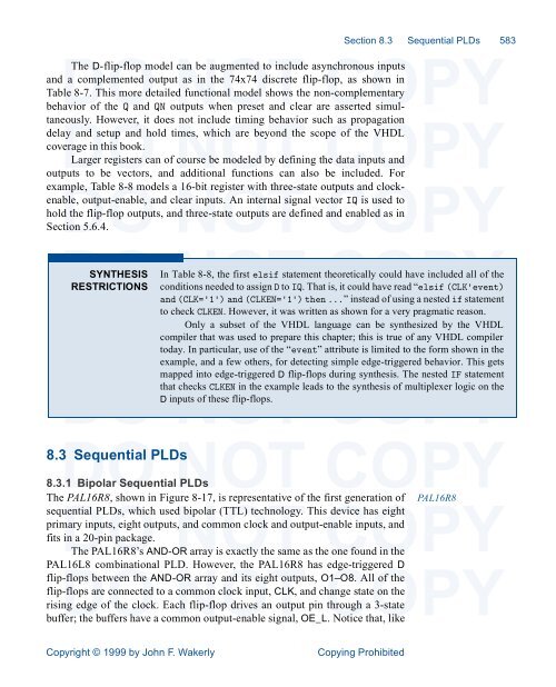
Section 8.3 Sequential PLDs 583DOThe D-flip-flop modelNOTcan be augmented to include asynchronousCOPYinputsand a complemented output as in the 74x74 discrete flip-flop, as shown inTable 8-7. This more detailed functional model shows the non-complementarybehavior of the Q and QN outputs when preset and clear are asserted simultaneously.DOHowever, it doesNOTnot include timing behavior suchCOPYas propagationdelay and setup and hold times, which are beyond the scope of the VHDLcoverage in this book.Larger registers can of course be modeled by defining the data inputs andoutputs to be vectors, and additional functions can also be included. Forexample,DOTable 8-8 models aNOT16-bit register with three-state outputsCOPYand clockenable,output-enable, and clear inputs. An internal signal vector IQ is used tohold the flip-flop outputs, and three-state outputs are defined and enabled as inSection 5.6.4.DO NOT COPYSYNTHESIS In Table 8-8, the first elsif statement theoretically could have included all of theRESTRICTIONS conditions needed to assign D to IQ. That is, it could have read “elsif (CLK'event)and (CLK='1') and (CLKEN='1') then ...” instead of using a nested if statementDOto checkNOTCLKEN. However, it was writtenCOPYas shown for a very pragmatic reason.Only a subset of the VHDL language can be synthesized by the VHDLcompiler that was used to prepare this <strong>chapter</strong>; this is true of any VHDL compilertoday. In particular, use of the “event” attribute is limited to the form shown in theexample, and a few others, for detecting simple edge-triggered behavior. This getsmapped into edge-triggeredDO NOTD flip-flops during synthesis. The nested IF statementCOPYthat checks CLKEN in the example leads to the synthesis of multiplexer logic on theD inputs of these flip-flops.DO NOT COPY8.3 Sequential PLDs8.3.1 Bipolar Sequential PLDsThe PAL16R8, shown in Figure 8-17, is representative of the first generation of PAL16R8sequentialDOPLDs, which usedNOTbipolar (TTL) technology. ThisCOPYdevice has eightprimary inputs, eight outputs, and common clock and output-enable inputs, andfits in a 20-pin package.The PAL16R8’s AND-OR array is exactly the same as the one found in thePAL16L8 combinational PLD. However, the PAL16R8 has edge-triggered DDO NOT COPYflip-flops between the AND-OR array and its eight outputs, O1–O8. All of theflip-flops are connected to a common clock input, CLK, and change state on therising edge of the clock. Each flip-flop drives an output pin through a 3-statebuffer; the buffers have a common output-enable signal, OE_L. Notice that, likeCopyright © 1999 by John F. WakerlyCopying Prohibited


