

Developement Of An Instrument Landing Simulation ... - Cal Poly
Developement Of An Instrument Landing Simulation ... - Cal Poly
Developement Of An Instrument Landing Simulation ... - Cal Poly

You also want an ePaper? Increase the reach of your titles
YUMPU automatically turns print PDFs into web optimized ePapers that Google loves.
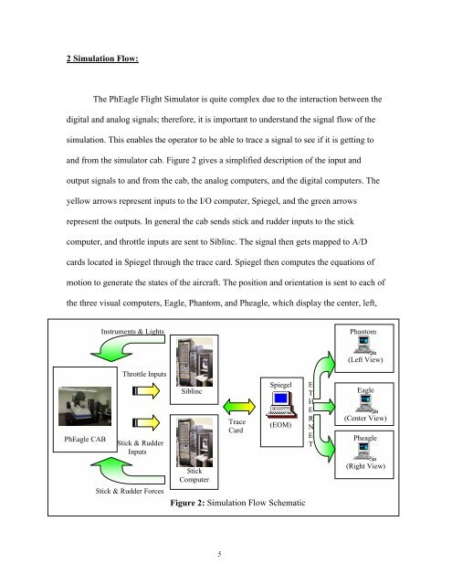
2 <strong>Simulation</strong> Flow:The PhEagle Flight Simulator is quite complex due to the interaction between thedigital and analog signals; therefore, it is important to understand the signal flow of thesimulation. This enables the operator to be able to trace a signal to see if it is getting toand from the simulator cab. Figure 2 gives a simplified description of the input andoutput signals to and from the cab, the analog computers, and the digital computers. Theyellow arrows represent inputs to the I/O computer, Spiegel, and the green arrowsrepresent the outputs. In general the cab sends stick and rudder inputs to the stickcomputer, and throttle inputs are sent to Siblinc. The signal then gets mapped to A/Dcards located in Spiegel through the trace card. Spiegel then computes the equations ofmotion to generate the states of the aircraft. The position and orientation is sent to each ofthe three visual computers, Eagle, Phantom, and Pheagle, which display the center, left,<strong>Instrument</strong>s & LightsPhantom(Left View)PhEagle CABThrottle InputsStick & RudderInputsSiblincTraceCardSpiegel(EOM)ETHERNETEagle(Center View)PheagleStick & Rudder ForcesStickComputerFigure 2: <strong>Simulation</strong> Flow Schematic(Right View)5


