

Developement Of An Instrument Landing Simulation ... - Cal Poly
Developement Of An Instrument Landing Simulation ... - Cal Poly
Developement Of An Instrument Landing Simulation ... - Cal Poly

Create successful ePaper yourself
Turn your PDF publications into a flip-book with our unique Google optimized e-Paper software.
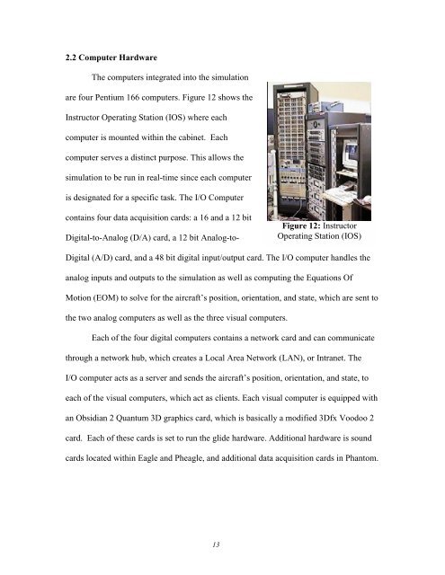
2.2 Computer HardwareThe computers integrated into the simulationare four Pentium 166 computers. Figure 12 shows theInstructor Operating Station (IOS) where eachcomputer is mounted within the cabinet. Eachcomputer serves a distinct purpose. This allows thesimulation to be run in real-time since each computeris designated for a specific task. The I/O Computercontains four data acquisition cards: a 16 and a 12 bitDigital-to-<strong>An</strong>alog (D/A) card, a 12 bit <strong>An</strong>alog-to-Figure 12: InstructorOperating Station (IOS)Digital (A/D) card, and a 48 bit digital input/output card. The I/O computer handles theanalog inputs and outputs to the simulation as well as computing the Equations <strong>Of</strong>Motion (EOM) to solve for the aircraft’s position, orientation, and state, which are sent tothe two analog computers as well as the three visual computers.Each of the four digital computers contains a network card and can communicatethrough a network hub, which creates a Local Area Network (LAN), or Intranet. TheI/O computer acts as a server and sends the aircraft’s position, orientation, and state, toeach of the visual computers, which act as clients. Each visual computer is equipped withan Obsidian 2 Quantum 3D graphics card, which is basically a modified 3Dfx Voodoo 2card. Each of these cards is set to run the glide hardware. Additional hardware is soundcards located within Eagle and Pheagle, and additional data acquisition cards in Phantom.13


