Developement Of An Instrument Landing Simulation ... - Cal Poly
Developement Of An Instrument Landing Simulation ... - Cal Poly
Developement Of An Instrument Landing Simulation ... - Cal Poly
You also want an ePaper? Increase the reach of your titles
YUMPU automatically turns print PDFs into web optimized ePapers that Google loves.
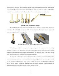
2.4.1 Stick and Rudder SignalsThe stick and rudder can receive stick force commands from the simulation basedon the amount of g’s being generated by the aircraft maneuvers. This force is sent to thestick computer, which sends the signal to the stick and rudder torque motors to generatethe force. These forces can generate up to 50 pounds of force.2.4.2 <strong>Instrument</strong> and Console SignalsFrom Siblinc, several connectors split the signalfrom Siblinc to the instruments and consoles. Initially, thesignal gets sent to the cockpit junction box (CJB) where itthen gets sent to the instrument panel motherboardassembly. Two connectors attach the signals to themotherboard, these are known as IJ1 & IJ2. Figure14shows these connectors mounted to the motherboard. Thesignal finally reaches its destination target by a connectionto one of the instruments from the motherboard.Figure 14: IJ1 &IJ2Figure 15 shows the back of theinstruments with their connections linking them tothe motherboard assembly. A tag on eachinstrument describes the channel number of theinstrument. This is the same channel as on Siblinc.Figure 15: <strong>Instrument</strong> Connections19


