Medical Applications Guide (Rev. B - Mouser Electronics
Medical Applications Guide (Rev. B - Mouser Electronics
Medical Applications Guide (Rev. B - Mouser Electronics

You also want an ePaper? Increase the reach of your titles
YUMPU automatically turns print PDFs into web optimized ePapers that Google loves.
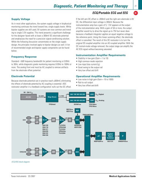
Diagnostic, Patient Monitoring and TherapyECG/Portable ECG and EEG21➔Supply VoltageAs in most other applications, the system supply voltage in biophysicalmonitoring continues the trend toward low, single-supply levels. Whilebipolar supplies are still used, 5V systems are now common and trendingto single 3.3V supplies. This trend presents a significant challengefor the designer faced with at least a 300mV DC electrode potentialand emphasizes the need for a precision signal-conditioning solution.While the following discussion concentrates on the single supplydesign, the principles involved apply to bipolar designs as well. A listof recommended single and bipolar supply components can be foundbelow.Frequency ResponseStandard –3dB frequency bandwidth for patient monitoring is 0.05Hzto 30Hz, while diagnostic grade monitoring requires 0.05Hz to 100Hz ormore. The analog front end must be AC coupled to remove artifactsfrom the electrode offset potential.Electrode PotentialBecause electrode potential can in practice reach ±500mV, eliminatingthe effects of electrode potential by AC coupling is essential. ADCrestorator amplifier in a feedback configuration nulls out the DC offset.If the left arm DC offset is +300mV and the right arm electrode is 0VDC, the differential input voltage is 300mV. Because theinstrumentation amp has a gain of 5, 1.5V appears at the outputof the instrumentation amp. With a gain of 50 or more, the outputamplifier would try to drive the signal up to 75V but never doesbecause a feedback integrator applies an equal negative voltage tothe reference point. Using this linear summing effect, the electrodeoffset is cancelled. The result of this DC restorator is to turn theoriginal DC-coupled amplifier into an AC-coupled amplifier. With theDC normal-mode voltage removed, the output stage can amplify theAC ECG signal without becoming saturated.Instrumentation Amplifier Requirements• Stability in low gain (Gain = 1 to 10)• High common-mode rejection• Low input bias current (I B )• Good swing to the output rail• Very low offset and driftOperational Amplifier Requirements• Low noise in high gain (Gain = 10 to 1000)• Rail-to-rail output• Very low offset and drift90 - 264 V AC12-24V 5-10VAC/DCStep Down3kV 1W ISO DC/DCLDOV CC Digital3kV 1W ISO DC/DCLDOV CC AnalogTPS54x0 DCH01xx TPS799xxTPS795xxREF32xxREF31xxREFTMS320F28xxCH1LPFLPFG=10HPFG=10LPFRCADCINA128INA118INA121INA326INA122INA126TLC2254OPA4348TLV2434OPA434xTLV2264ADS834xADS1258DSPDigitalµC SignalIFIsolationMSP430FxxISO72XSN65HVDxxCH32/64LPFLPFLPFG=10 HPF G=10 RC ADCECG/EEG block diagram.Texas Instruments 2Q 2007<strong>Medical</strong> <strong>Applications</strong> <strong>Guide</strong>