48➔<strong>Medical</strong> ImagingUltrasound/Portable Ultrasoundperformance is defined by the magnitude of the input signal. The ratiobetween these two signals defines the dynamic range of the system.Many receive chains integrate the LNA with a variable gain amplifier.Low-pass filtering is typically used between the VCA and the ADC asan anti-aliasing filter and to limit the noise bandwidth. Depending onthe specific system two- to five-pole filter, linear phase topologiescan be found here. In selecting an op amp, the primary considerationsinclude signal swing, minimum and maximum input frequencies, harmonicdistortion and gain requirements. Analog-to-digital converters(ADCs) are typically 10- and 12-bit. SNR and power consumption arethe most important issues, followed by channel integration.Another trend in ADCs is the implementation of an LVDS interfacebetween the ADC and the beamformer. By serializing the data comingout of the ADC, the number of interface lines can be reduced from6144 to 1024 for a 512-channel system. This reduction translatesto smaller and lower-cost PC boards, an essential part of portableimaging systems.Among the functions the DSP can perform in the imaging systemare the Doppler processing, 2D, 3D and even 4D imaging as well asa host of post processing algorithms to increase functionality andimprove performance. The key requirements of the imaging systemare high performance and high bandwidth. The TMS320C6455BZTZDSP meets both these needs. The C6455 runs at 1GHz to handle theintensive processing needs of ultrasound and the SerialRapidIOperipheral provides 10Gb/s full duplex bandwidth.There are many different levels of performance and functionality inultrasound systems. Some solutions may have pieces that require ahigh dynamic range or that have functions that take far less cycles todo in floating point. Examples of these type of functions are spectralreduction and square root functions. The TMS320C6727 fits very wellfor these areas where floating point works best. When an ultrasoundsolution requires an operating system, the TMS320DM6446 mayfill the need. In addition to having a powerful TMS32CC64x+ coreand video accelerators to handle the imaging needs, the DM6446 alsohas an ARM9 core capable of handling the OS requirements.The signal assembly is accomplished with a digital beamformer.This is typically a custom-designed ASIC, but this function has beenimplemented in different forms of programmable logic. Within thebeamformer the digitized signal is scaled and time delayed to createthe focusing effect in the receive chain. The properly adjusted signalsare then summed together across all receive channels and passedto the imaging system. The imaging system can be developed as aseparate ASIC, can be a programmable processor such as a DSP, ormight be a full desktop computer.Transmit elements require the control of 100V to 200V of signal swing.This is almost always accomplished with the use of high-voltage FETs.Control of the FETs can take one of two forms: on-off (push-pull) orclass-AB linear control. The most popular is the push-pull approach,as it requires a much simpler and lower-cost interface to the FETs.The class-AB approach dramatically improves harmonic distortionbut requires more complex drivers and consumes more power.A wide variety of TI products have been chosen by system andequipment manufacturers for their ultrasound imaging applications,including op amps; single, dual and octal ADCs (all with fast-inputoverload recovery and excellent dynamic performance); digital signalprocessors; and the VCA8617, an integrated 8-channel, low-powerultrasound front-end IC. TI is also offering the ADS5270, an advanced8-channel, 12-bit data converter with serialized LVDS interface,specifically for the ultrasound market.TUS5000EVM Allows Rapid Prototypingfor Ultrasound <strong>Applications</strong>The TUS5000EVM was designed to interface four two-channelVCA2615 variable gain amplifiers with the 8-channel ADS5272serialized LVDS-output ADC. A high-performance clock synchronizerand jitter cleaner, the CDCM7005, provides the 65MHz clock to theADS5272 with a bypass option available. Designers can simply applytheir real world input circuitry, such as an ultrasound probe, to theevaluation module to quickly evaluate the performance of TI's analogreceive chain solution.With a combined power per channel of 277mW, the VCA2615 andADS5272 can be used for midrange and high-performance ultrasoundapplications.A deserializer such as TI's ADSDESER-50EVM, is necessary in orderto convert the serial LVDS outputs of the ADS5272 to parallel datafor a complete evaluation.Pricing and AvailabilityThe TUS5000EVM is available today from TI. The price of $299includes the evaluation module and User's <strong>Guide</strong>. The ADSDESER-50EVM is also available today from TI. The price of $399 includesthe evaluation module, datasheet and User's <strong>Guide</strong>.TransducerInputVCA2615VCA2615VCA2615VCA2615High-performance ultrasound signal chain.MSP430ADS5272CDCM70058 Eight-ChannelSerialized LVDSto Data Evaluation<strong>Medical</strong> <strong>Applications</strong> <strong>Guide</strong> Texas Instruments 2Q 2007
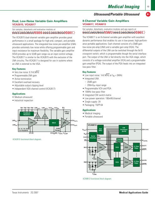
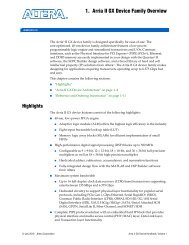
<strong>Medical</strong> ImagingUltrasound/Portable Ultrasound49➔Dual, Low-Noise Variable Gain AmplifiersVCA2615, VCA2617Get samples, datasheets and evaluation modules at:www.ti.com/sc/device/VCA2615, www.ti.com/sc/device/VCA2617The VCA2615 dual-channel variable gain amplifier provides greatperformance in a small package for high-end, compact, and portableultrasound applications. The integrated low noise pre-amplifier (LNA)provides extremely low noise while offering programmable gain andinput resistance for maximum flexibility. The variable gain amplifier(VGA) provides up to 52dB gain range via an input control voltage.The VCA2617 is similar to the VCA2615 with the exclusion of theLNA circuitry. The VCA2617 is designed for use in systems wherean LNA is external to the VGA.Key Features• Very low noise: 0.7nV/ Hz• Programmable LNA gain• Active termination• Excellent overload recovery• Adjustable output clipping level• Independent VGA channel control (VCA2617)<strong>Applications</strong>• <strong>Medical</strong> ultrasound• Industrial inspectionFB1 FB2 FB3 FB4 LNP OUT– LNP OUT+ VCA IN+ VCA IN–FeedbackResistors+1+1H/L(0dB or+6dB)8-Channel Variable Gain AmplifiersVCA8617, VCA8613Get samples, datasheets, evaluation modules and app reports at:www.ti.com/sc/device/VCA8617, www.ti.com/sc/device/VCA8613The VCA8617 is an 8-channel variable gain amplifier with excellentdynamic performance that enables its use in low-power, high-performanceportable applications. Each channel consists of a 20dB gainlow-noise pre-amp (LNA) and a variable gain amp (VGA). Thedifferential outputs of the LNA can be switched through the 8x10crosspoint switch, which is programmable though the serial interfaceport. The output of the LNA is fed directly into the VGA stage, whichconsists of a voltage-controlled amplifier (VCA) and a programmablegain amplifier (PGA). The output of the PGA feeds into an integratedlow-pass filter.Key Features• Low input noise: 1nV/ Hz at f IN = 5MHz• Integrated LNA• 20dB gain• 200mV PP input range• Programmable VCA and PGA• 15MHz low-pass filter• Integrated CW switch matrix• Low power operation: 100mW/channel• Single supply: 3V• Packaging: TQFP-64<strong>Applications</strong>• <strong>Medical</strong> imaging• Portable ultrasoundLNP IN+LNPLNP IN-(3, 12, 18, 22dB)1/2 VCA2615G1 G2VCA2615 functional block diagram.MUX52dBRangeVGAVCA IN SEL V CNTL V CLMPVCA OUT+VCA OUT-D OUTD INCLKCSVCA8613SerialInterface5x8FIFOPGATNAnalogControlCWProcessor(8x10)10CW (0-9)V CNTRLIN1LNAVCAPGA2- PoleFilterOUT1OUT1IN8V LNALNAVCAPGA2- PoleFilterOUT8OUT8V LNAVCA8613 functional block diagram.Texas Instruments 2Q 2007<strong>Medical</strong> <strong>Applications</strong> <strong>Guide</strong>
- Page 1 and 2: TMTechnology for InnovatorsMedical
- Page 3 and 4: Consumer and Portable Medical Devic
- Page 6: 6➔Consumer and Portable Medical D
- Page 9 and 10: Consumer and Portable Medical Devic
- Page 11 and 12: Consumer and Portable Medical Devic
- Page 13: Consumer and Portable Medical Devic
- Page 16 and 17: 16➔Consumer and Portable Medical
- Page 18 and 19: 18➔Consumer and Portable Medical
- Page 20 and 21: 20 Diagnostic, Patient Monitoring a
- Page 22 and 23: 22➔Diagnostic, Patient Monitoring
- Page 24 and 25: 24➔Diagnostic, Patient Monitoring
- Page 26 and 27: 26➔Diagnostic, Patient Monitoring
- Page 28 and 29: 28➔Diagnostic, Patient Monitoring
- Page 30 and 31: 30➔Diagnostic, Patient Monitoring
- Page 32 and 33: 32➔Diagnostic, Patient Monitoring
- Page 34 and 35: 34➔Diagnostic, Patient Monitoring
- Page 36 and 37: 36➔Diagnostic, Patient Monitoring
- Page 38 and 39: 38➔Diagnostic, Patient Monitoring
- Page 40 and 41: 40➔Diagnostic, Patient Monitoring
- Page 42 and 43: 42➔Diagnostic, Patient Monitoring
- Page 44 and 45: 44➔Diagnostic, Patient Monitoring
- Page 46 and 47: 46➔Diagnostic, Patient Monitoring
- Page 50 and 51: 50➔Medical ImagingUltrasound/Port
- Page 52 and 53: 52➔Medical ImagingUltrasound/Port
- Page 54 and 55: 54➔Medical ImagingComponent Recom
- Page 56 and 57: 56➔Medical ImagingCT ScannersDual
- Page 58 and 59: 58➔Medical ImagingComponent Recom
- Page 60 and 61: 60➔Medical ImagingMagnetic Resona
- Page 62 and 63: 62➔Medical ImagingMagnetic Resona
- Page 64 and 65: 64➔Medical ImagingComponent Recom
- Page 66 and 67: 66➔Medical ImagingDigital X-Raybl
- Page 68 and 69: 68➔Medical ImagingDigital X-RayLo
- Page 70 and 71: 70➔Medical ImagingPET ScannersPET
- Page 72 and 73: 72➔Medical ImagingComponent Recom
- Page 74 and 75: 74➔Medical ImagingPower Managemen
- Page 76 and 77: 76 Medical Instruments➔Medical In
- Page 78 and 79: 78➔Medical InstrumentsMedical Ins
- Page 80 and 81: 80 Resources➔Enhanced ProductTexa
- Page 82 and 83: 82➔ResourcesTI Design ToolsBelow
- Page 84: TMTechnology for InnovatorsFindProd