34➔Diagnostic, Patient Monitoring and TherapyVentilation/Pressure DiscussionPressure sensors convert a physical value–weight, tire pressure, level,force, and flow–into a differential signal in the mV/V range and arereferred to as metal thick-film, ceramic or piezo-resistive. The majorityof designers use the cost-effective piezo-sensors (25mbar – 25bar).However, these are very nonlinear, temperature dependent and havelarge offset and offset drift. Plus, they require attention to electroniccalibration and compensation.The block diagram (below) shows the functional block diagram of apressure signal conditioning system.Sensor Signal Conditioning — performs all necessary functionsto calibrate, compensate for temperature variance, scale, and linearizethe sensor signal.Analog/Digital Processing — there are two ways to convert andlinearize the sensor signal. The analog technique results in an analogsolution and provides an analog output. This technique is inexpensiveand fast, but limited to a maximum of 11- to 16-bit resolution.Digital is more precise, up to 24-bits, and provides a digital outputat moderate speed.The bridge excitation linearization circuit is optimized for bridgepressure nonlinearities with a parabolic shape (at right). Thelinearization circuit is digitally programmable, but the pure analogsignal conditioning side is handled by the same process as in TI’swell-known 4-20mA transmitters, such as XTR105, XTR106 or XTR108.The heart of the PGA309 is a precision, low-drift programmable gaininstrumentation amplifier using an auto-zero technique and includes aprogrammable fault monitor and over/underscale limiter. It also offersa digital temperature compensation circuit. Calibration is carried outeither via a one-wire digital serial interface or through a two-wireindustry-standard connection.Nonlinaerity (%FSR)2.72.42.11.81.51.20.90.60.30CorrectedBridge OutputUncorrectedBridge Output–0.30 1 2 3 4 5 6 7 8 9 10Bridge Output (mV)PGA309 bridge pressure nonlinearity correction.Calibration parameters are stored in an external nonvolatile memory toeliminate manual trimming and achieve long-term stability. An evaluationmodule, PGA309EVM (see below) includes software and calibrationsheet for easy evaluation of your sensor + PGA309 combination.The highly integrated, CMOS PGA309, available in TSSOP-16, istailored for bridge pressure sensors and adds to TI’s portfolio of highlyflexible, lowest noise amplifier and instrumentation amplifier solutionsthat also include the OPAx227, OPAx132, OPA335, OPA735, INA326,INA327, INA118 and INA122.PowerSupply+ –V SCustomerSensorRS232V CCPRGV INGNDSDASCLV OUTGNDPRG10nF–PGA309+PCEEPROMPGA309PC Interface BoardTemperatureChamberPGA309Sensor Interface Board–40˚C < Temperature < +125˚CPressureInputBlock diagram of the PGA390EVM module.<strong>Medical</strong> <strong>Applications</strong> <strong>Guide</strong> Texas Instruments 2Q 2007
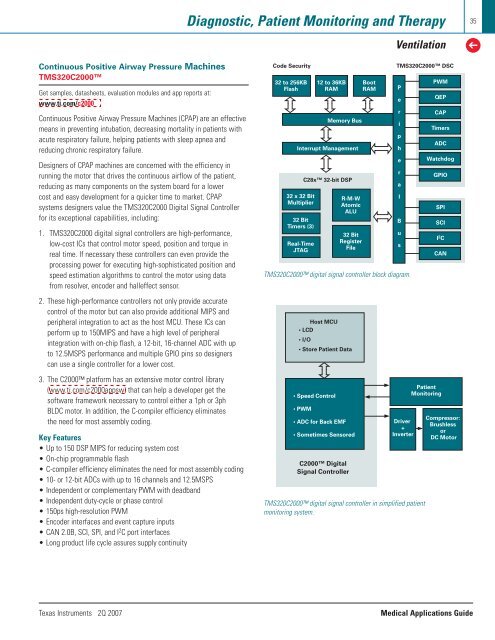
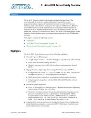
Diagnostic, Patient Monitoring and TherapyVentilation35➔Continuous Positive Airway Pressure MachinesTMS320C2000Get samples, datasheets, evaluation modules and app reports at:www.ti.com/c2000Continuous Positive Airway Pressure Machines (CPAP) are an effectivemeans in preventing intubation, decreasing mortality in patients withacute respiratory failure, helping patients with sleep apnea andreducing chronic respiratory failure.Designers of CPAP machines are concerned with the efficiency inrunning the motor that drives the continuous airflow of the patient,reducing as many components on the system board for a lowercost and easy development for a quicker time to market. CPAPsystems designers value the TMS320C2000 Digital Signal Controllerfor its exceptional capabilities, including:1. TMS320C2000 digital signal controllers are high-performance,low-cost ICs that control motor speed, position and torque inreal time. If necessary these controllers can even provide theprocessing power for executing high-sophisticated position andspeed estimation algorithms to control the motor using datafrom resolver, encoder and halleffect sensor.2. These high-performance controllers not only provide accuratecontrol of the motor but can also provide additional MIPS andperipheral integration to act as the host MCU. These ICs canperform up to 150MIPS and have a high level of peripheralintegration with on-chip flash, a 12-bit, 16-channel ADC with upto 12.5MSPS performance and multiple GPIO pins so designerscan use a single controller for a lower cost.3. The C2000 platform has an extensive motor control library(www.ti.com/c2000appsw) that can help a developer get thesoftware framework necessary to control either a 1ph or 3phBLDC motor. In addition, the C-compiler efficiency eliminatesthe need for most assembly coding.Key Features• Up to 150 DSP MIPS for reducing system cost• On-chip programmable flash• C-compiler efficiency eliminates the need for most assembly coding• 10- or 12-bit ADCs with up to 16 channels and 12.5MSPS• Independent or complementary PWM with deadband• Independent duty-cycle or phase control• 150ps high-resolution PWM• Encoder interfaces and event capture inputs• CAN 2.0B, SCI, SPI, and I 2 C port interfaces• Long product life cycle assures supply continuityCode Security32 to 256KBFlash32 x 32 BitMultiplier32 BitTimers (3)Real-TimeJTAG12 to 36KBRAMMemory BusInterrupt ManagementC28x 32-bit DSPR-M-WAtomicALU32 BitRegisterFileBootRAMTMS320C2000 digital signal controller block diagram.Host MCU• LCD• I/O• Store Patient Data• Speed Control• PWM• ADC for Back EMF• Sometimes SensoredC2000 DigitalSignal ControllerTMS320C2000 DSCPeripheralBusDriver+InverterTMS320C2000 digital signal controller in simplified patientmonitoring system.PWMQEPCAPTimersADCWatchdogGPIOSPISCII 2 CCANPatientMonitoringCompressor:BrushlessorDC MotorTexas Instruments 2Q 2007<strong>Medical</strong> <strong>Applications</strong> <strong>Guide</strong>
- Page 1 and 2: TMTechnology for InnovatorsMedical
- Page 3 and 4: Consumer and Portable Medical Devic
- Page 6: 6➔Consumer and Portable Medical D
- Page 9 and 10: Consumer and Portable Medical Devic
- Page 11 and 12: Consumer and Portable Medical Devic
- Page 13: Consumer and Portable Medical Devic
- Page 16 and 17: 16➔Consumer and Portable Medical
- Page 18 and 19: 18➔Consumer and Portable Medical
- Page 20 and 21: 20 Diagnostic, Patient Monitoring a
- Page 22 and 23: 22➔Diagnostic, Patient Monitoring
- Page 24 and 25: 24➔Diagnostic, Patient Monitoring
- Page 26 and 27: 26➔Diagnostic, Patient Monitoring
- Page 28 and 29: 28➔Diagnostic, Patient Monitoring
- Page 30 and 31: 30➔Diagnostic, Patient Monitoring
- Page 32 and 33: 32➔Diagnostic, Patient Monitoring
- Page 36 and 37: 36➔Diagnostic, Patient Monitoring
- Page 38 and 39: 38➔Diagnostic, Patient Monitoring
- Page 40 and 41: 40➔Diagnostic, Patient Monitoring
- Page 42 and 43: 42➔Diagnostic, Patient Monitoring
- Page 44 and 45: 44➔Diagnostic, Patient Monitoring
- Page 46 and 47: 46➔Diagnostic, Patient Monitoring
- Page 48 and 49: 48➔Medical ImagingUltrasound/Port
- Page 50 and 51: 50➔Medical ImagingUltrasound/Port
- Page 52 and 53: 52➔Medical ImagingUltrasound/Port
- Page 54 and 55: 54➔Medical ImagingComponent Recom
- Page 56 and 57: 56➔Medical ImagingCT ScannersDual
- Page 58 and 59: 58➔Medical ImagingComponent Recom
- Page 60 and 61: 60➔Medical ImagingMagnetic Resona
- Page 62 and 63: 62➔Medical ImagingMagnetic Resona
- Page 64 and 65: 64➔Medical ImagingComponent Recom
- Page 66 and 67: 66➔Medical ImagingDigital X-Raybl
- Page 68 and 69: 68➔Medical ImagingDigital X-RayLo
- Page 70 and 71: 70➔Medical ImagingPET ScannersPET
- Page 72 and 73: 72➔Medical ImagingComponent Recom
- Page 74 and 75: 74➔Medical ImagingPower Managemen
- Page 76 and 77: 76 Medical Instruments➔Medical In
- Page 78 and 79: 78➔Medical InstrumentsMedical Ins
- Page 80 and 81: 80 Resources➔Enhanced ProductTexa
- Page 82 and 83: 82➔ResourcesTI Design ToolsBelow
- Page 84:
TMTechnology for InnovatorsFindProd