FilmTec Technical Manual - Chester Paul Company
FilmTec Technical Manual - Chester Paul Company
FilmTec Technical Manual - Chester Paul Company

You also want an ePaper? Increase the reach of your titles
YUMPU automatically turns print PDFs into web optimized ePapers that Google loves.
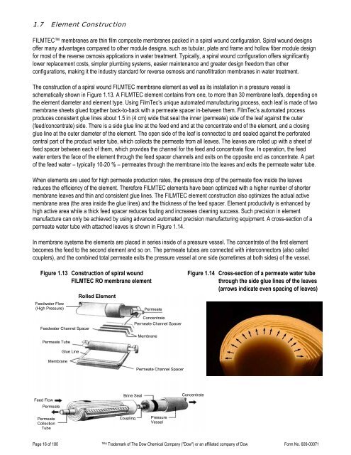
1.7 Element ConstructionFILMTEC membranes are thin film composite membranes packed in a spiral wound configuration. Spiral wound designsoffer many advantages compared to other module designs, such as tubular, plate and frame and hollow fiber module designfor most of the reverse osmosis applications in water treatment. Typically, a spiral wound configuration offers significantlylower replacement costs, simpler plumbing systems, easier maintenance and greater design freedom than otherconfigurations, making it the industry standard for reverse osmosis and nanofiltration membranes in water treatment.The construction of a spiral wound FILMTEC membrane element as well as its installation in a pressure vessel isschematically shown in Figure 1.13. A FILMTEC element contains from one, to more than 30 membrane leafs, depending onthe element diameter and element type. Using <strong>FilmTec</strong>’s unique automated manufacturing process, each leaf is made of twomembrane sheets glued together back-to-back with a permeate spacer in-between them. <strong>FilmTec</strong>’s automated processproduces consistent glue lines about 1.5 in (4 cm) wide that seal the inner (permeate) side of the leaf against the outer(feed/concentrate) side. There is a side glue line at the feed end and at the concentrate end of the element, and a closingglue line at the outer diameter of the element. The open side of the leaf is connected to and sealed against the perforatedcentral part of the product water tube, which collects the permeate from all leaves. The leaves are rolled up with a sheet offeed spacer between each of them, which provides the channel for the feed and concentrate flow. In operation, the feedwater enters the face of the element through the feed spacer channels and exits on the opposite end as concentrate. A partof the feed water – typically 10-20 % – permeates through the membrane into the leaves and exits the permeate water tube.When elements are used for high permeate production rates, the pressure drop of the permeate flow inside the leavesreduces the efficiency of the element. Therefore FILMTEC elements have been optimized with a higher number of shortermembrane leaves and thin and consistent glue lines. The FILMTEC element construction also optimizes the actual activemembrane area (the area inside the glue lines) and the thickness of the feed spacer. Element productivity is enhanced byhigh active area while a thick feed spacer reduces fouling and increases cleaning success. Such precision in elementmanufacture can only be achieved by using advanced automated precision manufacturing equipment. A cross-section of apermeate water tube with attached leaves is shown in Figure 1.14.In membrane systems the elements are placed in series inside of a pressure vessel. The concentrate of the first elementbecomes the feed to the second element and so on. The permeate tubes are connected with interconnectors (also calledcouplers), and the combined total permeate exits the pressure vessel at one side (sometimes at both sides) of the vessel.Figure 1.13 Construction of spiral woundFILMTEC RO membrane elementFeedwater Flow(High Pressure)Rolled ElementPermeateFigure 1.14 Cross-section of a permeate water tubethrough the side glue lines of the leaves(arrows indicate even spacing of leaves)Feedwater Channel SpacerPermeate TubeConcentratePermeate Channel SpacerMembraneMembraneGlue LinePermeate Channel SpacerFeed FlowPermeatePermeateCollectionTubeBrine Seal ConcentrateCoupling PressureVesselPage 16 of 180 ® Trademark of The Dow Chemical <strong>Company</strong> ("Dow") or an affiliated company of Dow Form No. 609-00071