- Page 1 and 2: DowWater SolutionsFILMTEC Reverse O
- Page 3: 2.6 Biological Fouling Prevention .
- Page 7 and 8: 1. Basics of Reverse Osmosis and Na
- Page 9 and 10: Nanofiltration (NF)Nanofiltration r
- Page 11 and 12: How to Use Reverse Osmosis and Nano
- Page 13 and 14: 1.4 Membrane DescriptionThe FILMTEC
- Page 15 and 16: Membrane systems are typically desi
- Page 17 and 18: 1.8 Element CharacteristicsFILMTEC
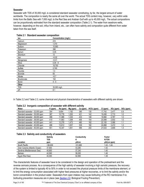
- Page 19: 2. Water Chemistry and Pretreatment
- Page 23 and 24: Table 2.5 Water analysis for RO/NFS
- Page 25 and 26: Table 2.7 Solubility products of sp
- Page 27 and 28: In this process, only Ca 2+ , Ba 2+
- Page 29 and 30: For the concentration ranges presen
- Page 31 and 32: The conditions for CaCO 3 scale con
- Page 33 and 34: Figure 2.3 Langelier saturation ind
- Page 35 and 36: These computations have been descri
- Page 37 and 38: Figure 2.5 “K” versus ionic str
- Page 39 and 40: Figure 2.6 Ksp for CaSO 4 versus io
- Page 41 and 42: 2.4.6 Calcium Fluoride Scale Preven
- Page 43 and 44: Figure 2.8 K sp for SrSO 4 versus i
- Page 45 and 46: 2.4.7 Silica Scale PreventionDissol
- Page 47 and 48: Table 2.10 Solubility of SiO 2 vers
- Page 49 and 50: 2.4.8 Calcium Phosphate Scale Preve
- Page 51 and 52: Table 2.9 Various fouling indicesIn
- Page 53 and 54: Frequent shutdowns and start-ups sh
- Page 55 and 56: If the differential pressure across
- Page 57 and 58: 1. Intake (surface) or well, before
- Page 59 and 60: or combined residual chlorine (CRC)
- Page 61 and 62: 2.6.5 DBNPADBNPA (2,2, dibromo-3-ni
- Page 63 and 64: 2.6.11 Use of Fouling Resistant Mem
- Page 65 and 66: 2.11 Treatment of Feedwater Contain
- Page 67 and 68: 2.13 Summary of Pretreatment Option
- Page 69 and 70: 26. Handbook of Industrial Membrane
- Page 71 and 72:
Table 3.1 System design information
- Page 73 and 74:
3.2 Batch vs. Continuous ProcessAn
- Page 75 and 76:
3.4 Single-Stage SystemIn a single-
- Page 77 and 78:
The apparent salt passage of the sy
- Page 79 and 80:
Instead of having a separate high-p
- Page 81 and 82:
3.9.1 Membrane System Design Guidel
- Page 83 and 84:
In Table 3.6, the small commercial
- Page 85 and 86:
Table 3.8 Number of stages of a sea
- Page 87 and 88:
3.11 System Performance Projection3
- Page 89 and 90:
3.11.2 Design Equations and Paramet
- Page 91 and 92:
Table 3.10 Design equations for pro
- Page 93 and 94:
3.11.3 Comparing Actual Performance
- Page 95 and 96:
The high-pressure concentrate is fe
- Page 97 and 98:
If the product water from an RO sys
- Page 99 and 100:
Besides the above recommendations,
- Page 101 and 102:
4. Loading of Pressure VesselsThis
- Page 103 and 104:
The process of shimming is performe
- Page 105 and 106:
4.5.2 Summary of Large Element Inte
- Page 107 and 108:
5. System Operation5.1 Introduction
- Page 109 and 110:
5.2.3 Start-Up SequenceProper start
- Page 111 and 112:
5.2.4 Membrane Start-Up Performance
- Page 113 and 114:
5.5.3 SeawaterIn principle, the ope
- Page 115 and 116:
Table 5.1 Reverse osmosis operating
- Page 117 and 118:
A. Normalized Permeate FlowQS=ΔPsP
- Page 119 and 120:
For the operating conditions we hav
- Page 121 and 122:
4. During recirculation of cleaning
- Page 123 and 124:
2. The cleaning pump should be size
- Page 125 and 126:
6.7 Effect of pH on Foulant Removal
- Page 127 and 128:
Cleaning ProcedureThere are seven s
- Page 129 and 130:
If the organic fouling is the resul
- Page 131 and 132:
There are two factors that greatly
- Page 133 and 134:
7. Handling, Preservation and Stora
- Page 135 and 136:
7.4 Preservation of RO and NF Syste
- Page 137 and 138:
If the normalized actual performanc
- Page 139 and 140:
8.3.3 Localization of High Solute P
- Page 141 and 142:
Figure 8.2 Permeate probing apparat
- Page 143 and 144:
8.4.5 Performance TestThe standard
- Page 145 and 146:
8.5.1.1 Low Flow and Normal Solute
- Page 147 and 148:
. Metal Oxide FoulingMetal oxide fo
- Page 149 and 150:
. Organic FoulingThe adsorption of
- Page 151 and 152:
8.5.3 High Pressure DropHigh differ
- Page 153 and 154:
In case of fullfit or heat sanitiza
- Page 155 and 156:
Breakpoint chlorinationBreak tankBr
- Page 157 and 158:
FeedThe input solution to a treatme
- Page 159 and 160:
Milligram per litre (mg/L)Mixed-bed
- Page 161 and 162:
SBS Sodium bisulfite, NaHSO 3.Scale
- Page 163 and 164:
9.2 Specific Conductance of Sodium
- Page 165 and 166:
Figure 9.1 Conductivity of ionic so
- Page 167 and 168:
9.6 Temperature Correction FactorTa
- Page 169 and 170:
9.9 Osmotic Pressure of Sodium Chlo
- Page 171 and 172:
Details - TestEquipment andSpecific
- Page 173 and 174:
satisfactory for such a determinati
- Page 175 and 176:
case for almost all tested biocides
- Page 177 and 178:
9.12 Key Word IndexAbrasion - 150 B
- Page 179 and 180:
Positive displacement pump - 95 Shu