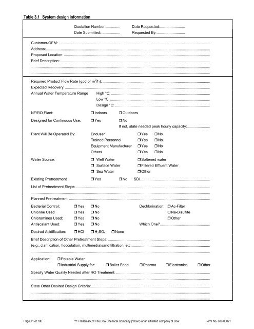
3. System Design3.1 IntroductionAn entire reverse osmosis (RO)/nanofiltration (NF) water treatment system consists of the pretreatment section, themembrane element section, and the post-treatment section. Pretreatment techniques are discussed in Section 2, WaterChemistry and Pretreatment. Post-treatment is employed to achieve the required product quality. In seawater desalination,this is usually pH adjustment, rehardening and disinfection. In ultrapure water (UPW) production, the permeate is usuallypost-treated by polishing ion exchange demineralization.In this section, the membrane system is addressed. The system includes a set of membrane elements, housed in pressurevessels that are arranged in a certain manner. A high-pressure pump is used to feed the pressure vessels. Instrumentation,spare parts and tools for services are added as required. A clean-in-place (CIP) system facilitates cleaning of themembranes. This is described in Section 6, Cleaning and Sanitization.The membrane system is a complete plant with an inlet for feed water and outlets for permeate and concentrate. RO/NFsystem performance is typically characterized by two parameters, permeate (or product) flow and permeate quality. Theseparameters should always be referenced to a given feed water analysis, feed pressure and recovery. The goal of thedesigner of an RO/NF system for a certain required permeate flow is to minimize feed pressure and membrane costs whilemaximizing permeate quality and recovery.The optimum design depends on the relative importance of these aspects. The recovery of brackish water systems is limitedby the solubility of sparingly soluble salts (see Section 2.4, Scaling Calculations)—90% is about the maximum. In seawaterdesalination, the limit of about 50% recovery is dictated by the osmotic pressure of the concentrate stream, whichapproaches the physical pressure limit of the FILMTEC seawater element.Obtaining the requested salt rejection is mainly a matter of membrane selection. The NF (NF270 > NF200 > NF90), brackishwater (BW) (extra low energy (XLE) > BW30LE > BW30), SW (seawater), and SWHR (seawater high rejection) versions ofthe FILMTEC NF and RO membrane have higher salt rejections in this order, but they also need higher feed pressuresunder the same conditions. Therefore, the NF to BW30LE membrane is typically applied to feed waters up to 2,000 mg/Ltotal dissolved solids (TDS), BW30 up to 10,000 mg/l, and SW and SWHR to high salinity feed waters up to 50,000 mg/L.For given operating conditions, the permeate quality can be calculated.The feed pressure needed to produce the required permeate flow for a given membrane depends on the designed permeateflux (permeate flow rate per unit membrane area). The higher the permeate flow per unit of active membrane area, thehigher the feed pressure. In seawater systems the permeate flux is relatively low even at maximum allowed pressure.However, the permeate flux could be very high in brackish water systems without reaching the limit of 600 psi (41 bar) forbrackish water elements. Although it is tempting to increase the permeate flux to minimize the costs for membrane elements,the flux has to be limited to minimize fouling.From experience, the flux limit to be used in system design depends on the fouling tendency of the feed water. A systemdesigned with high permeate flux rates is likely to experience higher fouling rates and more frequent chemical cleaning. Onlyexperience can set the limits on permeate flux for different types of waters. When designing a membrane system for aspecific feed water, it is advantageous to know the performance of other membrane systems operating on the same water.However, quite often there are no other membrane systems for comparison. Then the system design suggestions in DesignGuidelines for 8-inch (Section 3.9.1) and Midsize FILMTEC elements (Section 3.9.2) could be followed.Further information required to design a system is best collected by using the forms of Table 3.1 and Table 3.2. The morecomplete this information, the better the system design can be optimized towards the customer’s needs.Page 70 of 180 ® Trademark of The Dow Chemical <strong>Company</strong> ("Dow") or an affiliated company of Dow Form No. 609-00071
Table 3.1 System design informationQuotation Number:.............. Date Requested:........................Date Submitted: .................. Requested By: ...........................Customer/OEM: .................................................................................................................................................Address:.............................................................................................................................................................Proposed Location: ............................................................................................................................................Brief Description:......................................................................................................................................................................................................................................................................................................................................................................................................................................................................................................Required Product Flow Rate (gpd or m 3 /h): .......................................................................................................Expected Recovery:...........................................................................................................................................Annual Water Temperature Range High °C: ...............................................................................................Low °C:................................................................................................Design °C: ...........................................................................................NF/RO Plant: Indoors OutdoorsDesigned for Continuous Use: Yes NoIf not, state needed peak hourly capacity:......................Plant Will Be Operated By: Enduser Yes NoTrained Personnel Yes NoEquipment Manufacturer Yes NoOthers Yes NoWater Source: Well Water Softened water Surface Water Filtered Effluent Water Sea Water OtherExisting Pretreatment Yes No SDI...................................................................List of Pretreatment Steps:............................................................................................................................................................................................................................................................................................................Planned Pretreatment: .......................................................................................................................................Bacterial Control: Yes No Dechlorination: Ac-FilterChlorine Used Yes No Na-BisulfiteChloramines Used: Yes No OtherAntiscalant Used: Yes No Which One?................................................Desired Acidification: HCl H 2 SO 4 NoneBrief Description of Other Pretreatment Steps:..................................................................................................(e.g., clarification, flocculation, multimedia/sand filtration, etc.......................................................................................................................................................................................................................................................Application: Potable Water Industrial Supply for: Boiler Feed Pharma Electronics OtherSpecify Water Quality Needed after RO Treatment: .....................................................................................................................................................................................................................................................................State Other Desired Design Criteria:........................................................................................................................................................................................................................................................................................................................................................................................................................................................................Page 71 of 180 ® Trademark of The Dow Chemical <strong>Company</strong> ("Dow") or an affiliated company of Dow Form No. 609-00071
- Page 1 and 2:
DowWater SolutionsFILMTEC Reverse O
- Page 3:
2.6 Biological Fouling Prevention .
- Page 7 and 8:
1. Basics of Reverse Osmosis and Na
- Page 9 and 10:
Nanofiltration (NF)Nanofiltration r
- Page 11 and 12:
How to Use Reverse Osmosis and Nano
- Page 13 and 14:
1.4 Membrane DescriptionThe FILMTEC
- Page 15 and 16:
Membrane systems are typically desi
- Page 17 and 18:
1.8 Element CharacteristicsFILMTEC
- Page 19 and 20: 2. Water Chemistry and Pretreatment
- Page 21 and 22: SeawaterSeawater with TDS of 35,000
- Page 23 and 24: Table 2.5 Water analysis for RO/NFS
- Page 25 and 26: Table 2.7 Solubility products of sp
- Page 27 and 28: In this process, only Ca 2+ , Ba 2+
- Page 29 and 30: For the concentration ranges presen
- Page 31 and 32: The conditions for CaCO 3 scale con
- Page 33 and 34: Figure 2.3 Langelier saturation ind
- Page 35 and 36: These computations have been descri
- Page 37 and 38: Figure 2.5 “K” versus ionic str
- Page 39 and 40: Figure 2.6 Ksp for CaSO 4 versus io
- Page 41 and 42: 2.4.6 Calcium Fluoride Scale Preven
- Page 43 and 44: Figure 2.8 K sp for SrSO 4 versus i
- Page 45 and 46: 2.4.7 Silica Scale PreventionDissol
- Page 47 and 48: Table 2.10 Solubility of SiO 2 vers
- Page 49 and 50: 2.4.8 Calcium Phosphate Scale Preve
- Page 51 and 52: Table 2.9 Various fouling indicesIn
- Page 53 and 54: Frequent shutdowns and start-ups sh
- Page 55 and 56: If the differential pressure across
- Page 57 and 58: 1. Intake (surface) or well, before
- Page 59 and 60: or combined residual chlorine (CRC)
- Page 61 and 62: 2.6.5 DBNPADBNPA (2,2, dibromo-3-ni
- Page 63 and 64: 2.6.11 Use of Fouling Resistant Mem
- Page 65 and 66: 2.11 Treatment of Feedwater Contain
- Page 67 and 68: 2.13 Summary of Pretreatment Option
- Page 69: 26. Handbook of Industrial Membrane
- Page 73 and 74: 3.2 Batch vs. Continuous ProcessAn
- Page 75 and 76: 3.4 Single-Stage SystemIn a single-
- Page 77 and 78: The apparent salt passage of the sy
- Page 79 and 80: Instead of having a separate high-p
- Page 81 and 82: 3.9.1 Membrane System Design Guidel
- Page 83 and 84: In Table 3.6, the small commercial
- Page 85 and 86: Table 3.8 Number of stages of a sea
- Page 87 and 88: 3.11 System Performance Projection3
- Page 89 and 90: 3.11.2 Design Equations and Paramet
- Page 91 and 92: Table 3.10 Design equations for pro
- Page 93 and 94: 3.11.3 Comparing Actual Performance
- Page 95 and 96: The high-pressure concentrate is fe
- Page 97 and 98: If the product water from an RO sys
- Page 99 and 100: Besides the above recommendations,
- Page 101 and 102: 4. Loading of Pressure VesselsThis
- Page 103 and 104: The process of shimming is performe
- Page 105 and 106: 4.5.2 Summary of Large Element Inte
- Page 107 and 108: 5. System Operation5.1 Introduction
- Page 109 and 110: 5.2.3 Start-Up SequenceProper start
- Page 111 and 112: 5.2.4 Membrane Start-Up Performance
- Page 113 and 114: 5.5.3 SeawaterIn principle, the ope
- Page 115 and 116: Table 5.1 Reverse osmosis operating
- Page 117 and 118: A. Normalized Permeate FlowQS=ΔPsP
- Page 119 and 120: For the operating conditions we hav
- Page 121 and 122:
4. During recirculation of cleaning
- Page 123 and 124:
2. The cleaning pump should be size
- Page 125 and 126:
6.7 Effect of pH on Foulant Removal
- Page 127 and 128:
Cleaning ProcedureThere are seven s
- Page 129 and 130:
If the organic fouling is the resul
- Page 131 and 132:
There are two factors that greatly
- Page 133 and 134:
7. Handling, Preservation and Stora
- Page 135 and 136:
7.4 Preservation of RO and NF Syste
- Page 137 and 138:
If the normalized actual performanc
- Page 139 and 140:
8.3.3 Localization of High Solute P
- Page 141 and 142:
Figure 8.2 Permeate probing apparat
- Page 143 and 144:
8.4.5 Performance TestThe standard
- Page 145 and 146:
8.5.1.1 Low Flow and Normal Solute
- Page 147 and 148:
. Metal Oxide FoulingMetal oxide fo
- Page 149 and 150:
. Organic FoulingThe adsorption of
- Page 151 and 152:
8.5.3 High Pressure DropHigh differ
- Page 153 and 154:
In case of fullfit or heat sanitiza
- Page 155 and 156:
Breakpoint chlorinationBreak tankBr
- Page 157 and 158:
FeedThe input solution to a treatme
- Page 159 and 160:
Milligram per litre (mg/L)Mixed-bed
- Page 161 and 162:
SBS Sodium bisulfite, NaHSO 3.Scale
- Page 163 and 164:
9.2 Specific Conductance of Sodium
- Page 165 and 166:
Figure 9.1 Conductivity of ionic so
- Page 167 and 168:
9.6 Temperature Correction FactorTa
- Page 169 and 170:
9.9 Osmotic Pressure of Sodium Chlo
- Page 171 and 172:
Details - TestEquipment andSpecific
- Page 173 and 174:
satisfactory for such a determinati
- Page 175 and 176:
case for almost all tested biocides
- Page 177 and 178:
9.12 Key Word IndexAbrasion - 150 B
- Page 179 and 180:
Positive displacement pump - 95 Shu