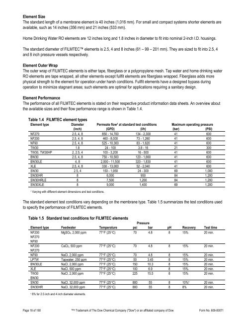
Element SizeThe standard length of a membrane element is 40 inches (1,016 mm). For small and compact systems shorter elements areavailable, such as 14 inches (356 mm) and 21 inches (533 mm).Home Drinking Water RO elements are 12 inches long and 1.8 inches in diameter to fit into nominal 2-inch I.D. housings.The standard diameter of FILMTEC elements is 2.5, 4 and 8 inches (61 – 99 – 201 mm). They are sized to fit into 2.5, 4and 8 inch pressure vessels respectively.Element Outer WrapThe outer wrap of FILMTEC elements is either tape, fiberglass or a polypropylene mesh. Tap water and home drinking waterRO elements are tape wrapped, all other elements except fullfit elements are fiberglass wrapped. Fiberglass adds morephysical strength to the element for operation under harsh conditions. Fullfit elements have a designed bypass duringoperation to minimize stagnant areas; such elements are optimal for applications requiring a sanitary design.Element PerformanceThe performance of all FILMTEC elements is stated on their respective product information data sheets. An overview aboutthe available sizes and their flow performance range is shown in Table 1.4.Table 1.4 FILMTEC element typesElement type Diameter Permeate flow 1 at standard test conditions Maximum operating pressure(inch) (GPD) (l/h) (bar) (PSI)NF270 2.5, 4, 8 850 - 14,700 134 - 2,300 41 600NF200 2.5, 4, 8 460 - 8,000 73 - 1,260 41 600NF90 2.5, 4, 8 525 - 10,300 83 - 1,620 41 600TW30 1.8 24 - 100 3.8 - 16 21 300TW30, TW30HP 2, 2.5, 4 100 - 3,200 16 - 500 41 600BW30 2.5, 4, 8 750 - 10,500 120 - 1,660 41 600BW30LE 4, 8 2,000 - 11,500 320 - 1,830 41 600XLE 2.5, 4, 8 330 - 13,000 52 - 2,040 41 600SW30 2.5, 4 150 - 1,950 24 - 300 69 1,000SW30HR 8 6,000 950 84 1,200SW30HRLE 8 7,500 1,200 84 1,200SW30XLE 8 9,000 1,400 69 1,2001 Varying with different element dimensions and test conditions.The standard element test conditions vary depending on the membrane type. Table 1.5 summarizes the test conditions usedto specify the performance of FILMTEC elements.Table 1.5 Standard test conditions for FILMTEC elementsPressureElement type Feedwater Temperature psi bar pH Recovery Test timeNF200MgSO4, 2,000 ppm 77°F (25°C) 70 4.8 8 15% 20 min.NF270NF90NF200CaCl2, 500 ppm 77°F (25°C) 70 4.8 8 15% 20 min.NF270NF90 NaCl, 2,000 ppm 77°F (25°C) 70 4.8 8 15% 20 min.LPTW Tapwater, 250 ppm 77°F (25°C) 50 3.45 8 15% 20 min.BW30LE NaCl, 2,000 ppm 77°F (25°C) 150 10.3 8 15% 20 min.XLE NaCl, 500 ppm 77°F (25°C) 100 6.9 8 15% 20 min.TW30NaCl, 2,000 ppm 77°F (25°C) 225 15.5 8 15% 20 min.BW30SW30 NaCl, 32,000 ppm 77°F (25°C) 800 55 8 10% † 20 min.SW30HR NaCl, 32,000 ppm 77°F (25°C) 800 55 8 8% 20 min.† 8% for 2.5 inch and 4 inch diameter elements.Page 18 of 180 ® Trademark of The Dow Chemical <strong>Company</strong> ("Dow") or an affiliated company of Dow Form No. 609-00071
2. Water Chemistry and Pretreatment2.1 IntroductionTo increase the efficiency and life of reverse osmosis and nanofiltration (RO/NF) systems, effective pretreatment of the feedwater is required. Selection of the proper pretreatment will maximize efficiency and membrane life by minimizing:• Fouling• Scaling• Membrane degradationOptimizing:• Product flow• Product quality (salt rejection)• Product recovery• Operating & maintenance costsFouling is the accumulation of foreign materials from feed water on the active membrane surface and/or on the feed spacerto the point of causing operational problems. The term fouling includes the accumulation of all kinds of layers on themembrane and feed spacer surface, including scaling. More specifically, colloidal fouling refers to the entrapment ofparticulate or colloidal matter such as iron flocs or silt, biological fouling (biofouling) is the growth of a biofilm, and organicfouling is the adsorption of specific organic compounds such as humic substances and oil on to the membrane surface.Scaling refers to the precipitation and deposition within the system of sparingly soluble salts including calcium carbonate,barium sulfate, calcium sulfate, strontium sulfate and calcium fluoride.Pretreatment of feed water must involve a total system approach for continuous and reliable operation. For example, animproperly designed and/or operated clarifier will result in loading the sand or multimedia filter beyond its operating limits.Such inadequate pretreatment often necessitates frequent cleaning of the membrane elements to restore productivity andsalt rejection. The cost of cleaning, downtime and lost system performance can be significant.The proper treatment scheme for feed water depends on:• Feed water source• Feed water composition• ApplicationThe type of pretreatment system depends to a large extent on feed water source (i.e., well water, surface water, andmunicipal wastewater). In general, well water is a consistent feed source that has a low fouling potential. Well water typicallyrequires a very simple pretreatment scheme such as acidification and/or antiscalant dosing and a 5-µm cartridge filter.Surface water, on the other hand, is a variable feed water source that is affected by seasonal factors. It has a high foulingpotential, both microbiological and colloidal. Pretreatment for surface water is more elaborate than pretreatment for wellwater. Additional pretreatment steps often include chlorination, coagulation/flocculation, clarification, multimedia filtration,dechlorination, acidification and/or antiscalant dosing.Industrial and municipal wastewaters have a wide variety of organic and inorganic constituents. Some types of organiccomponents may adversely affect RO/NF membranes, inducing severe flow loss and/or membrane degradation (organicfouling), making a well-designed pretreatment scheme imperative.Once the feed water source has been determined, a complete and accurate analysis of the feed water should be made. Theimportance of a feed water analysis cannot be overemphasized. It is critical in determining the proper pretreatment andRO/NF system design.Page 19 of 180 ® Trademark of The Dow Chemical <strong>Company</strong> ("Dow") or an affiliated company of Dow Form No. 609-00071
- Page 1 and 2: DowWater SolutionsFILMTEC Reverse O
- Page 3: 2.6 Biological Fouling Prevention .
- Page 7 and 8: 1. Basics of Reverse Osmosis and Na
- Page 9 and 10: Nanofiltration (NF)Nanofiltration r
- Page 11 and 12: How to Use Reverse Osmosis and Nano
- Page 13 and 14: 1.4 Membrane DescriptionThe FILMTEC
- Page 15 and 16: Membrane systems are typically desi
- Page 17: 1.8 Element CharacteristicsFILMTEC
- Page 21 and 22: SeawaterSeawater with TDS of 35,000
- Page 23 and 24: Table 2.5 Water analysis for RO/NFS
- Page 25 and 26: Table 2.7 Solubility products of sp
- Page 27 and 28: In this process, only Ca 2+ , Ba 2+
- Page 29 and 30: For the concentration ranges presen
- Page 31 and 32: The conditions for CaCO 3 scale con
- Page 33 and 34: Figure 2.3 Langelier saturation ind
- Page 35 and 36: These computations have been descri
- Page 37 and 38: Figure 2.5 “K” versus ionic str
- Page 39 and 40: Figure 2.6 Ksp for CaSO 4 versus io
- Page 41 and 42: 2.4.6 Calcium Fluoride Scale Preven
- Page 43 and 44: Figure 2.8 K sp for SrSO 4 versus i
- Page 45 and 46: 2.4.7 Silica Scale PreventionDissol
- Page 47 and 48: Table 2.10 Solubility of SiO 2 vers
- Page 49 and 50: 2.4.8 Calcium Phosphate Scale Preve
- Page 51 and 52: Table 2.9 Various fouling indicesIn
- Page 53 and 54: Frequent shutdowns and start-ups sh
- Page 55 and 56: If the differential pressure across
- Page 57 and 58: 1. Intake (surface) or well, before
- Page 59 and 60: or combined residual chlorine (CRC)
- Page 61 and 62: 2.6.5 DBNPADBNPA (2,2, dibromo-3-ni
- Page 63 and 64: 2.6.11 Use of Fouling Resistant Mem
- Page 65 and 66: 2.11 Treatment of Feedwater Contain
- Page 67 and 68: 2.13 Summary of Pretreatment Option
- Page 69 and 70:
26. Handbook of Industrial Membrane
- Page 71 and 72:
Table 3.1 System design information
- Page 73 and 74:
3.2 Batch vs. Continuous ProcessAn
- Page 75 and 76:
3.4 Single-Stage SystemIn a single-
- Page 77 and 78:
The apparent salt passage of the sy
- Page 79 and 80:
Instead of having a separate high-p
- Page 81 and 82:
3.9.1 Membrane System Design Guidel
- Page 83 and 84:
In Table 3.6, the small commercial
- Page 85 and 86:
Table 3.8 Number of stages of a sea
- Page 87 and 88:
3.11 System Performance Projection3
- Page 89 and 90:
3.11.2 Design Equations and Paramet
- Page 91 and 92:
Table 3.10 Design equations for pro
- Page 93 and 94:
3.11.3 Comparing Actual Performance
- Page 95 and 96:
The high-pressure concentrate is fe
- Page 97 and 98:
If the product water from an RO sys
- Page 99 and 100:
Besides the above recommendations,
- Page 101 and 102:
4. Loading of Pressure VesselsThis
- Page 103 and 104:
The process of shimming is performe
- Page 105 and 106:
4.5.2 Summary of Large Element Inte
- Page 107 and 108:
5. System Operation5.1 Introduction
- Page 109 and 110:
5.2.3 Start-Up SequenceProper start
- Page 111 and 112:
5.2.4 Membrane Start-Up Performance
- Page 113 and 114:
5.5.3 SeawaterIn principle, the ope
- Page 115 and 116:
Table 5.1 Reverse osmosis operating
- Page 117 and 118:
A. Normalized Permeate FlowQS=ΔPsP
- Page 119 and 120:
For the operating conditions we hav
- Page 121 and 122:
4. During recirculation of cleaning
- Page 123 and 124:
2. The cleaning pump should be size
- Page 125 and 126:
6.7 Effect of pH on Foulant Removal
- Page 127 and 128:
Cleaning ProcedureThere are seven s
- Page 129 and 130:
If the organic fouling is the resul
- Page 131 and 132:
There are two factors that greatly
- Page 133 and 134:
7. Handling, Preservation and Stora
- Page 135 and 136:
7.4 Preservation of RO and NF Syste
- Page 137 and 138:
If the normalized actual performanc
- Page 139 and 140:
8.3.3 Localization of High Solute P
- Page 141 and 142:
Figure 8.2 Permeate probing apparat
- Page 143 and 144:
8.4.5 Performance TestThe standard
- Page 145 and 146:
8.5.1.1 Low Flow and Normal Solute
- Page 147 and 148:
. Metal Oxide FoulingMetal oxide fo
- Page 149 and 150:
. Organic FoulingThe adsorption of
- Page 151 and 152:
8.5.3 High Pressure DropHigh differ
- Page 153 and 154:
In case of fullfit or heat sanitiza
- Page 155 and 156:
Breakpoint chlorinationBreak tankBr
- Page 157 and 158:
FeedThe input solution to a treatme
- Page 159 and 160:
Milligram per litre (mg/L)Mixed-bed
- Page 161 and 162:
SBS Sodium bisulfite, NaHSO 3.Scale
- Page 163 and 164:
9.2 Specific Conductance of Sodium
- Page 165 and 166:
Figure 9.1 Conductivity of ionic so
- Page 167 and 168:
9.6 Temperature Correction FactorTa
- Page 169 and 170:
9.9 Osmotic Pressure of Sodium Chlo
- Page 171 and 172:
Details - TestEquipment andSpecific
- Page 173 and 174:
satisfactory for such a determinati
- Page 175 and 176:
case for almost all tested biocides
- Page 177 and 178:
9.12 Key Word IndexAbrasion - 150 B
- Page 179 and 180:
Positive displacement pump - 95 Shu