Instruction Manuals - Cole-Parmer
Instruction Manuals - Cole-Parmer
Instruction Manuals - Cole-Parmer

Create successful ePaper yourself
Turn your PDF publications into a flip-book with our unique Google optimized e-Paper software.
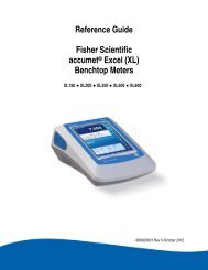
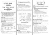
<strong>Instruction</strong> ManualpH 1100/ pH 2100Bench pH/Ion MeterTechnology Made Easy ...68X090818Rev. 5 May 07Part of ThermoFisher Scientific
<strong>Instruction</strong> Manual pH 1100/ 2100PREFACEThank you for selecting the pH 1100/ 2100 benchtop meter. This meter measure pH, millivolts, relative millivolts andtemperature. The pH 2100 meter also measures ion concentration.The instruction manual serves to explain the use of the pH 1100/ 2100 bench meter as a step-by-step operational guideto help you familiarize with the meter’s features and functions. It is structured sequentially with illustration of diagramsthat explains the various functions and setup menus available.This manual is written to cover as many anticipated applications and uses of the pH 1100/ 2100 Bench meter aspossible. If there are doubts in the use of the meter, please do not hesitate to contact the nearest Authorized Distributoror Customer Service Dept. for assistance.Eutech Instruments/ Oakton Instruments reserve the rights to change, make improvement and modify specificationswithout prior notice and cannot accept any responsibility for damage or malfunction to the instrument caused by improperuse.Copyright © 2002Eutech Instruments Pte. Ltd.Oakton InstrumentsAll rights reserved.Rev. 4 Jan 07
<strong>Instruction</strong> Manual pH 1100/ 2100TABLE OF CONTENTS1 INTRODUCTION 61.1 Introducing the Bench Meter Series 61.2 Keypad 71.3 Rear Panel 81.4 Electrode Holder 92 STARTING UP 102.1 Back Panel Connections 102.2 Powering up and powering down 102.2.1 Powering up 102.2.2 Powering down 103 PH CALIBRATION & MEASUREMENT 113.1 pH calibration 113.1.1 Automatic Temperature Compensation (ATC) 113.1.2 Starting pH calibration 123.1.3 Standard pH buffer calibration 133.1.4 Custom pH buffer calibration 143.1.5 Calibration error messages 153.2 pH measurement 163.2.1 Automatic temperature compensation 163.2.2 Adjusting manual temperature compensation 163.2.3 Taking pH Measurements 174 mV CALIBRATION AND MEASUREMENT 184.1 mV Calibration 184.1.1 mV Calibration error message 184.2 mV Measurement 195 ION CALIBRATION AND MEASUREMENT (ONLY APPLICABLE FOR pH 2100) 205.1 Ion calibration 205.2 Ion calibration error messages 215.3 Ion measurement 226 MEMORY FUNCTIONS 236.1 Memory input 236.1.1 Manually storing a reading into memory 236.2 Memory recall 246.2.1 Recalling readings in manual recall mode 246.2.2 Recalling readings in automatic recall mode 247 STABILITY INDICATOR 258 ALARM FUNCTIONS 258.1 High and Low measurement alarm 258.2 Calibration due alarm 259 TEMPERATURE CALIBRATION 269.1 Temperature Calibration 269.2 Temperature Calibration Error Messages 2610 SETUP MODE 2710.1 Setup mode overview 2710.1.1 pH/Temperature setup submenus 2710.1.2 mV setup submenus 2810.1.3 Ion setup submenus (pH 2100 only) 2810.1.4 Meter general configuration setup submenus 2910.2 pH/ temperature setup mode 3010.2.1 Entering pH/temperature setup mode 3010.2.2 pH buffer setup program P1.0 3010.2.3 pH resolution setup program P1.1 3110.2.4 Temperature unit setup program P1.2 3110.2.5 pH Measurement Alarm Setup Program P1.3 3210.2.6 pH Calibration Due Alarm Setup program P1.4 3310.2.7 Stability Setup Program P1.5 3410.2.8 View pH calibration data setup program P1.6 354
<strong>Instruction</strong> Manual pH 1100/ 210010.2.9 pH calibration data reset setup program P1.7 3610.3 mV setup mode 3710.3.1 Entering mV setup mode 3710.3.2 mV measurement alarm setup program P2.0 3810.3.3 mV calibration due alarm setup program P2.1 3910.3.4 Stability setup program P2.2 4010.3.5 View mV calibration data setup program P2.3 4110.3.6 mV calibration data reset setup program P2.4 4210.4 Ion setup mode (pH 2100 meter only) 4310.4.1 Entering ion setup mode 4310.4.2 Ion unit setup mode P3.0 4310.4.3 Ion measurement alarm setup program P3.1 4410.4.4 Ion calibration due alarm setup program P3.2 4510.4.5 Stability setup program P3.3 4610.4.6 Ion mode setup program P3.4 4710.4.7 View ion calibration data setup program P3.5 4810.4.8 Ion calibration data reset setup program P3.6 4910.5 Meter general configuration setup mode 5010.5.1 Entering meter general setup mode 5010.5.2 Date/time setup mode P4.0 5010.5.3 Backlight setup mode P4.1 5110.5.4 Data log setup mode P4.2 5210.5.5 Memory recall setup mode P4.3 5210.5.6 Communication setup mode P4.4 5310.5.7 Data transfer setup mode P4.5 5310.5.8 Memory clear setup mode P4.6 5410.5.9 Meter reset setup mode P4.7 5411 ELECTRODE CARE 5511.1 Electrode Activation 5511.2 Electrode Maintenance 5511.3 Storing pH/ORP electrodes 5512 RS 232 COMMUNICATION 5612.1 Using with printer 5612.1.1 Sending data to printer 5612.2 Using with computer 5613 ADDITIONAL INFORMATION 5713.1 pH and Temperature 5713.2 pH Buffer Calibration Solution 5713.3 Standard pH Buffers 5714 SUMMARY OF DEFAULT SETTINGS / OPTIONS 5815 TROUBLESHOOTING & ERROR MESSAGES 5916 SPECIFICATIONS 6017 ACCESSORIES 6118 WARRANTY 625
<strong>Instruction</strong> Manual pH 1100/ 21001 INTRODUCTION1.1 Introducing the Bench Meter SeriesThe pH 1100/ 2100 bench meter is microprocessor-based which incorporates new ASIC (Application Specific IntegratedCircuit). It is designed with convenience in mind and offers many advanced, user-friendly features. The meters arecapable of storing and recalling up to 100 data sets in its non-volatile memory. In addition, as a space saver, an optionalswivel electrode holder can be attached at the either side of bench meter for resting the electrodes and probes duringoperation.The pH 1100/ 2100-- bench meter measures pH, millivolts, relative millivolts and temperature. The pH 2100 meter alsomeasures ion concentration. These meters are equipped with a large customized LCD (Liquid Crystal Display) withsimultaneous display of the measured values for easy reading. It is most ideal for routine pH/Ion Concentrationmeasurement in indoor applications.6
<strong>Instruction</strong> Manual pH 1100/ 21001.2 KeypadSee Figure 1.A large membrane keypad with touch feedback makes the meter easy to use. Names and symbols describe the functionbutton controls.Figure 1: Membrane KeypadON/OFFENTEREXITPower meter On or OffConfirm selection in all modes of operations;Scroll through the sub-menus program in the SETUP modesExit from current modes of operations;Exit from calibration mode after 3 rd point calibration (for pH/Ion)CAL / ‣ Enter into calibration modes of the meter;Select or scroll to the next options availableMODEHOLDSETUPSelect the measurement modes:- pH, Ion Concentration, mV, Relative mVFreeze the displayed value; allow you to print the held reading or store it intomemoryEnter SETUP mode of the meter for customization of meter functions as well asview some diagnostic functions (refer to the table for details of SETUP menus)/ MI Store the displayed value into memory;Increment values or scroll through the next options available/ MR Recall stored values from the memory in the Last-In-First-Out (LIFO) sequence;Decrement values or scroll through the next options availablePRINTNumeric Keys (0-9 & .)Send measured data being measured or data stored in the memory to aperipheral device via the RS232C port of meterEnter numeric values and decimal point at appropriate places- (Minus) Enter negative sign at appropriate places7
<strong>Instruction</strong> Manual pH 1100/ 21001.3 Rear PanelSee Figure 2.The pH 1100/ 2100 meters provide a complete set of input connections for the various accessories commonly used.Listed in the table below are details of the connections that you can make.Figure 2: Rear View of MeterConnectorATCINPUTFunctionFor phono jack connection from the temperature probe for Automatic Temperature Compensation.The probe should be a 30KΩ thermistor probe.For connecting sensors with a BNC connector to the meter. The meter accepts any pH, ORP or ISEelectrode with a BNC connector. Always make sure that the connector is clean and dry.REFRECGNDRS232DCFor connection to the pin tip type reference electrode normally used with half cell (mono) type pH orISE electrodes.For connection to the strip chart recorder.For connection to the ground earth jack (standard pin tip connectors).For connection to the RS232C serial port.For connection of the AC adapter power supply (included).8
<strong>Instruction</strong> Manual pH 1100/ 21001.4 Electrode HolderThe electrode holder is included in the same box as the meter.To attach the electrode holder to the meter:1. The electrode holder base attached to thebottom of the meter comes in the shippingposition. See Figure 3.2. Use a Phillips screwdriver to remove thescrew holding the electrode holder inshipping position. See Figure 3.3. Slide the electrode base away from themeter until the second screw slot lines upwith the original screw hole. Use the screwremoved earlier to secure electrode holderbase into position. See Figure 3.4. The electrode holder arm is reversible. Ifdesired, remove screw holding electrodeholder base and slide base out of brackets.Slide base into brackets on opposite sideand replace screw.5. To install the electrode arm, turn meter backto the upright position. See Figure 4.6. Line up the hole on the base of theelectrode holder arm with the peg on theelectrode holder base. Slide the holesecurely onto the electrode holder base.See Figure 4.Figure 3: Bottom of Meter7. The electrode arm is now ready to swinginto desired position.Figure 4: Fix electrode holder arm to holder base9
<strong>Instruction</strong> Manual pH 1100/ 21002 STARTING UPAttention: Do not get water on the BNC connector during operation.Avoid touching the connector with soiled or wet hands.2.1 Back Panel ConnectionsRefer back to Figure 2. Make the necessary connections as mentioned in Section 1.3 Rear Panel, pg 8.2.2 Powering up and powering down2.2.1 Powering up1. When first connected to the power supply, the meter runs aself test, the display flashes Hardware Testing... Status:Pass.See Figure 5.2. It then displays current date and time. See Figure 6. Thisdisplay will also appear when the meter is turned off whilestill connected to the power supply. See Figure 6.3. See Figure 7. To turn the meter on press ON/OFF. Theupper display flashes Bench pH/Ion 2100 for the pH 2100,(Display flashes Bench pH 1100 for the pH 1100 meter.)and then the lower display flashes SW Rev 1.20. SeeFigure 7.4. The display flashes System Initializing, Please wait...See Figure 8.5. If this is the first power up since the power was connected,you must indicate desired measurement mode. Use >/CALto select. The mode selected will flash. See Figure 9.Press ENTER to confirm. The meter then entersmeasurement mode.6. After initial startup, the meter will automatically return tothe measurement mode previously selected as long aspower connection is maintained.Ha r d wa r e Tes t i n g . . . .St at us: PassFigure 5DateTimeJan 25 2002 09:09:30Figure 6Bench pH/ I on 2100SW Rev 1 .20Figure 7System I nitializingPl e as e wa i t . . .Figure 8pH/ Temp mV I onSel ec t & Pr es s ENTERFigure 92.2.2 Powering down1. To turn the meter off press ON/OFF. The display flashesSystem Shutting Down, Please wait... See Figure 10.Then, the date and time display will appear. See Figure 6.The date and time will continue to display until the powersupply is disconnected.Syst em Shut t ing DownPl e as e wa i t . . .Figure 1010
<strong>Instruction</strong> Manual pH 1100/ 21003 PH CALIBRATION & MEASUREMENT3.1 pH calibrationThis meter is capable of up to 5 point calibration with selectable buffer sets (USA, NIST, Bf1, Bf2 or any 5 custom buffersof your choice). The meter retains stored pH calibrations even when turned off. For best accuracy, we recommend thatyou perform at least a 2-point calibration using buffers that bracket (one above and one below) the expected samplerange. A single point cal is possible only at the offset points namely 7.00 or 6.86. For custom buffer sets, you mustperform at least a 2 point calibration.Selectable buffer sets:USA: 1.68, 4.01, 7.00, 10.01, 12.45NIST: 1.68, 4.01, 6.86, 9.18, 12.45Bf1: 1.68, 4.01, 7.00, 9.18, 12.45Bf2: 1.68, 4.01, 6.86, 10.01, 12.45Any 5 user selected custom buffersTo select which buffer sets you wish to use see Section 10.2.2: Program pH Buffer Setup: P1.0 in the pH/Temp setupmode (page 30).When you recalibrate your meter, old pH calibration points are replaced on a point by point basis. For example, if youpreviously calibrated your meter at pH 4.01, 7.00, and 10.01, and you recalibrate at pH 7.00, the meter retains the oldcalibration data at pH 4.01 and pH 10.01. To view current calibration points, see Section 10.2.8: Program pH Cal DataP1.6 in the pH/Temp setup mode (page 35).If you choose to recalibrate to only 1 or 2 pH values, the older calibration values you do not calibrate to will remain stored.These old stored calibration values may cause accuracy loss when your readings are close to the old values. To clear oldcalibration data, reset the meter as shown in Section 10.2.9 Program pH Cal Reset: P1.7 in the pH/Temp setup mode(page 36).3.1.1 Automatic Temperature Compensation (ATC)If you will be taking pH measurement using Automatic TemperatureCompensation (ATC), you must perform your pH calibration withATC temperature probe attached. Attach the temperature probe tothe rear of the meter. The ATC mode annunciator shows on thedisplay. See Figure 11. Insert the probe into the pH buffer solutionalong with your pH electrode.If manual temperature compensation is preferred, do not plug atemperature probe into the meter. The MTC mode annunciatorshows on the display. See Figure 12. The default manualtemperature compensation is 25.0°C. To change the manualtemperature compensation default, see Section 9 TemperatureCalibration for instructions (page 26).7.179pH 25.3°C ATCJan 18 2002 08:46:25Figure 117.179pH 25.3°C MTCJan 18 2002 08:46:25Figure 1211
<strong>Instruction</strong> Manual pH 1100/ 21003.1.2 Starting pH calibration1. Turn the meter ON. If the meter is not in the pH measurementmode, press EXIT and press >/CAL to select pH/Temp. Themode selected will flash. See Figure 13. Press ENTER toconfirm selection. The meter is now in pH measurement mode.See Figure 14.2. Rinse the electrode in deionized water or rinse solution. If usingthe ATC function with a separate temperature probe, rinse thetemperature probe as well. Do not wipe the pH electrode ortemperature probe dry. Wiping the probes causes static, andwill create calibration and measurement instability.3. Select pH buffer and pour into a clean container.4. Dip the electrode and ATC probe into the calibration buffer. Theend of the probes must be completely immersed into thesample. Stir probes gently to create a homogeneous sample.5. Press >/CAL to enter the pH calibration mode. The displayflashes Cal Mode Activated, Please wait....See Figure 15. The meter is now in pH calibration mode.pH/ Temp mV I onSel ec t & Pr es s ENTERFigure 137.179pH 25.3°C ATCJan 18 2002 08:46:25Figure 14Cal Mode Act ivat edPl e a s e wa i t . . .Figure 15The meter automatically recognizes the buffers in the set you have selected in the SETUP mode. If you wish to changethe buffer set selected, see Section 10.2.2, Program pH Buffer Setup: P1.0 in the pH/Temp setup mode (page 30).If your meter is set up for standard buffers (USA, NIST, Bf1, Bf2), proceed to Section 3.1.3: Standard pH buffercalibration (page 13). If your meter is set up for custom buffers, proceed to Section 3.1.4: Custom pH buffer calibration(page 14).12
<strong>Instruction</strong> Manual pH 1100/ 21003.1.3 Standard pH buffer calibration1. When entering the standard calibration mode, the first buffercalibration point for standard pH buffers is 7.000 or 6.860(depending upon which pH buffer set is selected). The upperdisplay shows the current reading, the lower display will showAuto Buf Scan: 7.000 (or 6.860). The upper display will flash pHuntil the reading has stabilized. See Figure 16. If the selectedbuffer value is not within ±1.0 of the measured pH value, theAuto pH Scan will continue to change until the pH buffer iswithin ±1.0.2. When pH reading has stabilized, press ENTER. The lowerdisplay flashes *pH Offset Cal Done. See Figure 17. Thiscalibration point is now stored in the meter.• If you are performing a one-point calibration, press EXIT.The screen flashes Sys Updating...Please wait....The meterthen returns to the pH measurement mode. You may nowstart taking pH readings.• If you are performing a multi-point calibration, go to step 3.3. Rinse the probe with deionized water or a rinse solution, andplace it in the next pH buffer. The lower display automaticallyscans to the next pH buffer solution.7.001pH 25.4°C ATCAut o Buf Scan: 7.000Figure 167.001pH 25.4°C ATC* pH Of f set Cal DoneErr or: Cal Abor t edFigure 1710.010pH 25.4°C ATC2 Point Cal Done *Figure 18Figure 194. Wait for the measured pH value to stabilize. The upper displaywill flash pH until the reading has stabilized.5. When pH reading has stabilized, press ENTER. The lowerdisplay flashes 2 Point Cal Done * (3 if you have calibrated 3points,4 if 4 points, etc.). See Figure 18. This calibration point isnow stored in the meter. Repeat steps 3-5 for each point youwish to calibrate. When you are finished calibrating, press EXIT.The screen flashes Sys. Updating... Please wait.... The meterthen returns to the pH measurement mode. You may now starttaking pH readings.6. If you perform a complete 5-point pH calibration, when youcalibrate the fifth point and press ENTER, the meterautomatically returns to measurement mode. You may now starttaking pH readings.NOTE:To exit from pH calibration mode at any point without confirming calibration, DO NOT press ENTER in steps 2, 5 or 6.Press EXIT instead. If EXIT is press before a 1-point calibration is performed the upper display flashes Error: Cal Aborted.See Figure 19.DO NOT REUSE SOLUTIONS AFTER CALIBRATION.Contaminants in the solution can affect the calibration, and eventually the accuracy of the measurements.13
<strong>Instruction</strong> Manual pH 1100/ 21003.1.4 Custom pH buffer calibration1. When entering the custom calibration mode, the lower displaywill show Key In Std:. The upper display shows the pH buffer theelectrode is dipped into. The lower display will show the samevalue as the upper display only if the meter has not beencalibrated or if the meter has been reset. See Figure 20. If themeter has previously been calibrated, the lower display willtoggle to the stored calibration point that is closest to currentbuffer value.7.179pH 25.3 ° ° CATCKey I n St d: 7.179Figure 202. Using the numeric keypad (See Figure 21), enter the value ofthe first custom pH buffer. If you make a mistake, use the Δ/MIor ∇/MR to highlight mistake, then retype.3. Press ENTER when first custom pH buffer is keyed in. Thedisplay will read 1 Point Cal Done *. See Figure 22.NOTE: In the custom pH buffer calibration mode you mustperform at least a 2-point calibration, if you press EXIT beforeyou calibrate at 2 points the screen will flash Error: Cal Aborted(See Figure 23) and will return to the pH measurement modewithout confirming any calibration points.4. Rinse the probe with deionized water or a rinse solution, andplace it in the next custom pH buffer. The lower display willshow Key In Std: The upper and lower displays show the pHbuffer value.5. Enter the value of the next custom pH buffer. Press ENTERwhen done. The display will read 2 Point Cal Done *. If you areperforming a 2-point calibration, press EXIT. The screen flashesSys Updating...Please wait... The meter then returns to the pHmeasurement mode. You may now start taking pH readings.• If you are performing a 3, 4 or 5-point calibration go to step6.6. Repeat steps 4 and 5 for each additional custom buffer. Uponconfirmation of pH buffer, the display will read 3 Point Cal Done* (4 if you have calibrated points, etc). When you have finishedcalibrating desired number of points, press EXIT. The screenflashes Sys. Updating... Please wait...The meter then returns to the pH measurement mode. If youhave entered 5 calibration points, the meter will automaticallyreturn to pH measurement mode. You may start taking pHreadings.Numeric KeypadEr r or : Cal Abor t edFigure 217.179pH 25.3 °CATC11Cal Point Point Cal Done* *Figure 22Figure 23NOTE:To exit from pH calibration mode at any point without confirming calibration, DO NOT press ENTER in steps 3 or 5. PressEXIT. If EXIT is pressed before a 2-point calibration is performed the upper display flashes Error: Cal Aborted. SeeFigure 23.DO NOT REUSE SOLUTIONS AFTER CALIBRATION.Contaminants in the solution can affect the calibration, and eventually the accuracy of the measurements.14
<strong>Instruction</strong> Manual pH 1100/ 21003.1.5 Calibration error messagesStandard pH Buffer Calibration:If the first buffer value of 7.000 or 6.860 is off by more than ±1.0,the upper display will flash Error: and the lower display will readpH Offset Error. See Figure 24. Press EXIT to clear errormessage and return to pH measurement mode.If any other pH buffer point is off by more than ±1.0, the upperdisplay will flash Error: and the lower display will read pH SlopeError. See Figure 25. Press EXIT, to clear error message andreturn to pH measurement mode.Custom pH Buffer Calibration:If the each custom pH buffer value is not within ±1.0 pH of thekeyed in value, the upper display will flash Error: and the lowerdisplay will read Too much offset @7pH. See Figure 26. PressEXIT to clear error message and return to pH measurementmode.If the slope is not within 75% to 105%, the upper display willflash Error: and the lower display will read Slope out: 75% -105%.See Figure 27. Press EXIT to clear error message and return topH measurement mode.If adjacent calibration points are less than ±1.0 pH apart, theupper display will read Error: Pts too close, and the lower displaywill read OR slope diff. sign. See Figure 28. Press EXIT to clearerror message and return to pH measurement mode./measurementEr r or :* pH Of f set Err orEr r or :* pH Slope Er rorFigure 24Figure 25Er r or :Too much Of f set @7Figure 26Er r or :Slope out :75% - 105%Figure 27Err or :Pt s t oo closeOr slope dif f . signFigure 2815
<strong>Instruction</strong> Manual pH 1100/ 21003.2 pH measurementThis meter is capable of taking measurements with automatic ormanual temperature compensation. Automatic TemperatureCompensation (ATC) occurs when a temperature sensor isplugged into the meter. If there is no temperature sensorplugged into the meter, the default setting is automatically 25°C(if the meter has never been manually set for temperature) or thelast manually set value. You can manually set the temperature to7.179pH 25.3°C ATCJan 18 2002 08:46:25Figure 29match your working conditions using a separate thermometer. pH/ Temp mV I onSel ec t & Pr es s ENTER3.2.1 Automatic temperature compensationFor automatic temperature compensation, simply plug thetemperature probe into the meter (see page 8). The ATCindicator will light on the LCD. See Figure 29.NOTE: If you are using a temperature probe, the probe must besubmersed in the liquid you are measuring.3.2.2 Adjusting manual temperature compensationIMPORTANT: For manual compensation, you must disconnectthe temperature probe.1. Turn the meter ON. If the meter is NOT in the pHmeasurement mode, press EXIT and use >/CAL to selectpH/Temp. The mode selected will flash. See Figure 30.Press ENTER to confirm selection. The meter is now in pHmeasurement mode. If the temperature probe isdisconnected, the upper display will indicate MTC. SeeFigure 31.2. Press >/CAL to enter pH/Temp calibration mode. Thedisplay will flash Cal Mode Activated, Please wait... Press>/CAL key again to enter the temperature calibration mode.The display will flash Temperature Cal Mode. See figure 32.The upper display then reads MTC Temp: 25.0°C and thelower display reads Key In Std: 25.0°C. See Figure 33.3. Check the temperature of your sample using an accuratethermometer.4. Key in the temperature value using the numeric keypad. Ifyou make a mistake, use the Δ/MI or∇/MR key to highlightmistake, then re-enter.5. Press ENTER to confirm temperature and to return to thepH measurement mode. Display will flash Temp CalComplete in the upper display and MTC Set Temp:(temperature that was keyed in). See Figure 34. The displaywill flash Sys. Updating...Please wait... The meter thenreturns to pH measurement mode and will now compensatepH reading with the manually set temperature.NOTE: To exit this program without confirming the manualtemperature compensation value, do not press ENTER in step 5.Press EXIT instead. The display will flash Error: Cal Aborted andmeter will return to pH measurement mode.Figure 307.179pH 25.3°C MTCJan 18 2002 08:46:25Figure 31Temperat ur e Cal ModeFigure 32MTC Temp : 25.0 ° CKey I n St d: 25.0 ° CTe mp Ca l Co mp l et eMT C Se t Te mp : 2 6 .5Figure 33° CFigure 3416
<strong>Instruction</strong> Manual pH 1100/ 21003.2.3 Taking pH MeasurementsNOTE: Be sure to remove the electrode soaker bottle orprotective rubber cap on the electrode before measurement.1. Rinse the probe with deionized or distilled water before useto remove any impurities adhering to the probe body. If thepH electrode dehydrated, soak it for 30 minutes in electrodestorage solution or a 2M to 4M KCl solution.2. Press ON. The upper display shows current pH reading andtemperature, and indicates automatic or manualtemperature compensation. The lower display shows month,date, year and time. See Figure 35.7.179pH 25.3°C ATCJan 18 2002 08:46:25Figure 357.546pH 25.4°C ATCJan 18 2002 08:46:30Figure 363. Dip the probe into the sample. Make sure the sensor or theglass bulb of the electrode is completely immersed into thesample. Stir the probe gently to create a homogenoussample.4. Allow time for the reading to stabilize. The pH indicatorblinks when reading is not stable. See Figure 36. When thereadings stabilizes, the pH indicator freezes and no longerblinks.17
<strong>Instruction</strong> Manual pH 1100/ 21004 mV CALIBRATION AND MEASUREMENT4.1 mV Calibration1. Turn the meter ON. If the meter is not in the mVmeasurement mode, press EXIT and use >/CAL to selectmV. The mode selected will flash. See Figure 37. PressENTER to confirm selection. The meter is now in absolutemV measurement mode. See Figure 38.2. Rinse the electrode in deionized water or rinse solution.Do not wipe the electrode dry. Wiping the probescauses static, and will create calibration andmeasurement instability.3. Select your standard and pour into a clean container.4. Dip the probe into the standard. The end of the probemust be completely immersed into the sample. Stir theprobe gently to create a homogeneous sample.5. Press >/CAL key to enter the mV calibration mode. Thedisplay will read Cal Mode Activated, Please wait... SeeFigure 39. The meter is now in mV calibration mode. Theupper display shows Abs. mV: and lower display showsKey in Std: See Figure 40.NOTE: In mV calibration, the value shown in the upperdisplay is the same as the lower display.6. Key in the mV value to match the standard value usingthe numeric keypad. If you make a mistake, use the Δ/MIor ∇/MR to highlight mistake, then re-enter.7. Press ENTER key to confirm the reading. The displayflashes mV Cal Completed, mV Offset: (shows the mVoffset value). See Figure 41. It then flashes SysUpdating... Please wait.... The meter returns to mVmeasurement mode. The upper display now reads Rel.mV. See Figure 42.NOTE: New mV calibrations will override existing the storedmV calibration data. The meter retains stored mV calibrationseven when the meter is turned off.To exit from mV calibration mode at any point withoutconfirming calibration, DO NOT press ENTER in step 7. PressEXIT.The upper display then flashes Error: Cal Aborted.See Figure 43.pH/ Temp mV I onSel ec t & Pr es s ENTERFigure 37Abs. mV : 226.9mVJan 20 2002 20:30:05Figure 38Ca l Mo d e Ac t i v a t e dPl ea s e wa i t . . .Figure 39Abs. mV : 226.9mVKey I n St d: 226 .9 mVFigure 40mV Ca l Co mp l e t e dmV Of f s e t : - 3 .7 mVFigure 41Rel. mV : 200.0mVJan 20 2002 20:34:45Er r or : Cal Abor t edFigure 42Figure 43Er r or :mV Of f set t oo lar geFigure 444.1.1 mV Calibration error messageIf the offset adjustment of your mV calibration is not within ±150.0 mV; the upper display will flash Error: and the lowerdisplay will read mV Offset too large. See Figure 44. Press EXIT to clear error message and return to mV measurementmode.18
<strong>Instruction</strong> Manual pH 1100/ 21004.2 mV Measurement1. Turn the meter ON. If the meter is NOT in the mVmeasurement mode, press EXIT and use >/CAL to select mV.The mode selected will flash. See Figure 45. Press ENTER toconfirm selection.The meter is now in Rel mV measurement mode. See Figure 46. Ifyou have not performed a mV calibration or have reset the meter,the display will read Abs. mV. See Figure 47.2. Dip the electrode into the sample. The sensor or glass bulb ofthe electrode must be completely immersed into the sample.Stir the electrode gently to create a homogeneous sample.3. Allow time for the reading to stabilize. The upper display willshow the mV reading, and the lower display will show thecurrent month, day and time. See Figure 46.pH/Temp mV IonSel ec t & Pr es s ENTERFigure 45Rel. mV : 200.0mVJan 20 2002 20:34:45Figure 46Abs. mV : 226.9mVJan 20 2002 20:30:05Figure 4719
<strong>Instruction</strong> Manual pH 1100/ 21005 ION CALIBRATION AND MEASUREMENT (ONLY APPLICABLE FOR pH 2100)The pH 2100 meter reads ion concentration in ppm, ppt, mg/l, g/l, mmol/l and mol/l units. See Ion setup Program P3.0(page 43) to select ion concentration units.5.1 Ion calibrationThis instrument is capable of up to 5-point custom ion calibration with a minimum of 2-point calibration. Customcalibration values can be any value between 0.001 and 19998. Once the first calibration value is keyed in, all othercalibration will automatically be at least one decade apart.For example if your first calibration point is at 0.001, all other calibration points will be at least one decade apart from0.001 (0.001, 0.01, 0.1,1.0, 10.0, 100, 1000, 10000).For best accuracy calibrate your meter to points with similar concentrations to the solutions you want to test.1. Connect an Ion Selective Electrode (ISE) to the BNC inputconnector on the back of the meter.2. Turn the meter ON. If the meter is not in the Ion measurementmode, press EXIT and use >/CAL to select Ion. The modeselected will flash. See Figure 48. Press ENTER to confirmselection. The meter is now in Ion measurement mode.3. If the meter has not been calibrated or has been reset, thedisplay will flash Ion Meas and current mV value. See Figure49. If the meter has been calibrated previously, the display willshow the current concentration value plus the absolute mVproduced by the electrode.4. Dip the electrode into the first calibration standard. Start withthe calibration standard that has the lowest concentration andmove up to higher concentration standards.pH/ Temp mV I onSel ec t & Pr es s ENTERI on Meas 160.3mVJan 20 2002 21:54:34Cal Mode Act ivat edPl ea s e wa i t . . .Figure 48Figure 49Figure 505. Press >/CAL to enter the ion calibration mode. The display willflash Cal Mode Activated, Please wait... See Figure 50. Thedisplay then shows Ion Conc: ppm (or unit selected in ionsetup mode) in the upper display and Abs. mV: in the lowerdisplay. See Figure 51.I on Conc:Abs. mV :ppm100.7mVFigure 516. The first calibration point must be keyed in by the user. Key inthe concentration value of the standard using the numerickeypad. If you make a mistake, use the Δ/MI or ∇/MR keys tohighlight mistake, then re-enter.7. Press ENTER to confirm the first calibration point. The displaywill flash 1 Cal Point Done *, then the meter proceeds to thenext calibration point at least 1 decade apart from the firstcalibration point. See Figure 52.8. Use Δ/MI or ∇/MR keys to move the cursor to next calibrationpoint. All points will be a decade apart from the first calibrationpoint.I on Conc:0.01ppm1 Point Cal Done *Figure 52I on Conc:0.10ppm2 Point Cal Done *Figure 539. Rinse off the electrode with deionized water before placing itin the next calibration standard.10. Allow probe to stabilize in calibration standard. Press ENTERto confirm. The display flashes 2 Point Cal Done *. SeeFigure 53.The meter proceeds to the next calibration point.20
<strong>Instruction</strong> Manual pH 1100/ 2100If you are performing a 2-point calibration, press EXIT.The screen flashes Aver. Slope = (the average slope of theelectrode) in the upper display and Sys Updating... in the lowerdisplay. See Figure 54. The meter returns to the Ion measurementmode. You may now start taking readings.If you are performing a 3, 4 or 5-point calibration go to step 11.11. Use Δ/MI or ∇/MR keys to move the cursor to next calibrationpoint.Av er . Sl ope = 49.2mVSys Updat ing. . .Figure 54I on Conc: 1.0ppm3 Point Cal Done *Figure 5512. Rinse off the electrode with deionized water before placing it inthe next calibration standard.13. Allow probe to stabilize in calibration standard. Press ENTERto confirm. The display flashes 3 Point Cal Done * (4 for 4 point,etc.).See Figure 55. The meter proceeds to the next calibrationpoint.14. Repeat steps 11-13 until you finish calibrating at desirednumber of points (up to 5 points). Press EXIT. The screenflashes Aver.Slope = (the average slope of the electrode) in theupper display and Sys Updating... in the lower display. SeeFigure 54. The meter returns to the Ion measurement mode.At the end of a 5-point calibration, the meter automaticallyflashes Aver. Slope = and Sys Updating, and returns tomeasurement mode.NOTES: You may compare the average electrode slope value withthe expected slope value for your electrode from your electrodemanual to verify electrode operation. If you want to leave thecalibration mode prior to confirming two calibration points, pressEXIT key to exit calibration mode. The meter will revert to back tothe earlier calibration curve. If you have calibrated to two points,pressing EXIT will confirm the new calibration. New ion calibrationswill over-ride the existing stored ion calibration data. The meterretains stored ion calibrations even when the meter is turned off orif the power cord is unplugged or power is cut off to the AC adapter.5.2 Ion calibration error messagesIf you leave the ion calibration mode prior to confirming twocalibration points by pressing the EXIT key, the screen will flashError: Cal Aborted. See Figure 56. The meter will revert to back tothe earlier calibration curve and return to the ion measurementmode.If the average ion slope is not within 10 to 75 mV per decade, theupper display will flash Error: and the lower display will read IonSlope Error. See Figure 57.Er r or : Cal Abor t edEr r or :I on Slope Err orFigure 56Figure 5721
<strong>Instruction</strong> Manual pH 1100/ 21005.3 Ion measurementThe pH 2100 meter features two different modes of ionmeasurement: high resolution mode and low resolution mode.These modes are user selectable in the Ion setup program P3.4.(page 47). The default is high resolution mode. Low resolutionmode should only be used if your ion solution concentration willproduce an absolute mV value of ±500 mV.1. Turn the meter ON. If the meter is NOT in the Ionmeasurement mode, press EXIT and use >/CAL to select Ion.The mode selected will flash. See Figure 58. Press ENTERto confirm selection. The meter is now in Ion measurementmode. If the meter has not been calibrated, or has been reset,the display will flash Ion Meas and current mV value. SeeFigure 59. If the meter has been calibrated, the display willshow the current concentration value plus the absolute mVproduced by the electrode.See Figure 60.pH/ Temp mV I onSel ec t & Pr es s ENTERFigure 58I on Meas 160.3mVJan 20 2002 21:54:34Figure 590.013ppm 160.3mVJan 21 2002 21:35:34Figure 602. Prepare samples as necessary. Sample preparations variesdepending on ion type—see your electrode manual for detailson the specific electrode that you are using.3. Dip electrode into the sample. The sensor or glass bulb of theelectrode must be completely immersed into the sample.4. Allow time for the reading to stabilize, then record yourmeasurement.NOTE: The display in the ion measurement mode shows mV thatcorrelates to the electrode output. Charge in mV will typically be59.7 mV for monovalent ions (1+ or 1- charge) and 29.8 mV fordivalent ions (2+ or 2- charge).22
<strong>Instruction</strong> Manual pH 1100/ 21006 MEMORY FUNCTIONS6.1 Memory inputThis meter can store up to 100 sets of data in several combinations:pH 1100 meter:• pH, temperature, date and time• mV, temperature, date and timepH 2100 meter:• pH, temperature, date and time• mV, temperature, date and time• ion, mV, date and timeFor example, you can store 32 pH and 68 mV values for the pH 1100 or 50 ion, 25 mV and 25 pH values for the pH 2100.This meter can be setup to log readings automatically or manually. To set the meter to log automatically, see MeterSetup Program P4.2, Data Log Setup (page 52). The meter can log readings at intervals from 10 seconds to 23 hours 59minutes and 59 seconds.6.1.1 Manually storing a reading into memory1. During any measurement mode function, press Δ/MI key toinput data into memory.5.695pH 25.3°C ATCDat a Log.... Loc: 9Figure 612. The upper display will read current measurement function andthe lower display will flash Data Log.... Loc: (the memorystorage location). See Figure 61. The meter then returns tomeasurement mode.NOTE: If the memory is full, the first value stored will be erased to create space for the new value.23
<strong>Instruction</strong> Manual pH 1100/ 21006.2 Memory recallThis function recalls the previous readings stored in the memory. You can only access memory recall from themeasurement mode. Memory recall is in “Last In First Out” (LIFO) order.There are two methods of viewing stored data in the memory recall function: manual and automatic. In manual memoryrecall, the user must manually scroll through the memory points using the Δ/MI and ∇/MR keys. In automatic memoryrecall, the meter automatically scrolls through the memory points. To choose the method of viewing stored data you wishto use, see Meter Setup mode Program P4.3 MemRecall Setup (page 52).6.2.1 Recalling readings in manual recall mode1. Press the ∇/MR key once to retrieve the last reading stored.The display flashes Mem Recall Activated, Please wait... SeeFigure 62.The display then flashes the memory location last stored in thelower display. See Figure 63. Then the display shows therecorded value (pH/temp, mV or Ion/mV) in the upper displayand toggles between memory location and date in the lowerdisplay. See Figures 64-65.2. Use the ∇/MR key to select the next memory location or theΔ/MI key to select the previous memory location.3. Repeat step 2 to review additional stored data sets.4. To exit Memory Recall, press EXIT and return to themeasurement mode.6.2.2 Recalling readings in automatic recall mode1. Press the ∇/MR key once to retrieve the last reading stored.The display flashes Mem Recall Activated, Please wait... SeeFigure 62. The display then flashes the memory location laststored in the lower display. See Figure 63. Then the displayshows the recorded value (pH/temp, mV or Ion/mV) in theupper display and date and time in the lower display. SeeFigure 64.2. After 8 seconds, the meter automatically scrolls to the next tomemory location. The display flashes the next memory locationstored. See Figure 66. The display then shows the recordedvalue (pH/temp, mV or Ion/mV) in the upper display and dateand time in the lower display. See Figure 67.Me m Re c a l l Ac t i v a t e dPl e as e wa i t . . .Me m L o c : 9Figure 62Figure 635.695pH 25.3°C ATCJan 21 2002 08:52:35Me m L o c : 8Figure 645.695pH 25.3°C ATCMem Loc:9 08:52:35Figure 65Figure 667.545pH 25.4°C ATCJan 18 2002 08:50:35Figure 673. The meter will continuously scroll through all the memory pointsstored indefinitely. To exit memory recall, press EXIT and returnto the measurement mode.NOTES: If no new readings are stored after memory recall functionhas been exited, the next time the memory recall function isactivated, it will resume at the memory location point where it waslast exited. If a new point is stored, the memory recall function willbegin with that point. Readings stored in memory are retained evenif the unit is turned off. To erase all readings stored in memory, seeMeter Setup Program P4.6, Mem Clear Setup (page 54).24
<strong>Instruction</strong> Manual pH 1100/ 21007 STABILITY INDICATORThe stability indicator signals when pH, mV or Ion readings are stable.The pH, mV or Ion annunciator will blink when reading are not stable.See Figure 68. Once the reading becomes stable the annunciatorbecomes static and no longer blinks.You can turn the stability indicator on and off and set the level ofstability in pH Setup Section P1.5 (page 34); mV Setup P2.2 (page40); and Ion Setup P3.3 (page 46).7.546pH 25.4°C ATCJan 18 2002 08:46:30Figure 688 ALARM FUNCTIONS8.1 High and Low measurement alarmYour meter has high and low measurement alarms that can be individually set for pH, mV and Ion (pH 2100 only). To sethigh and low measurement alarms, please refer to the setup sections pH Setup P1.3 (page 32); mV Setup P2.0 (page38); and Ion Setup P3.1 (page44).If the measured value exceeds the alarm setting, the meter will “beep”; the upper display flashes measured parameterflashes; and the lower displays Hi-Alarm or Lo-Alarm. See Figures 69 and 70.The following conditions are necessary to signal an alarm:• pH: The high alarm must be at least 1.0 pH greater thanthe low alarm• mV: The high alarm setting must be at least 100.0greater than the low alarm• Ion: The high alarm setting must be at least half of thenext decade greater than the low alarm2.852pH 25.3°C ATCLo-Alarm 08:46:25Figure 6913.278pH 28.6°C ATCHi-Alarm 08:46:25Figure 70pH Calibrat ion DueCalibrat ion Abort8.2 Calibration due alarmFigure 71You can set this meter to signal an alarm when calibration is due.Individual calibration due alarms can be set for pH, mV and Ion(pH 2100 only) at a period of 1 to 365 days from the last calibration.To set calibration due alarm, please refer to the setup sections pHSetup P1.4 (page 33); mV Setup P2.1 (page 39); and Ion SetupP3.2 (page 45). The meter will “beep” during power up ifcalibration is due. The upper display will read pH (mV or Ion)Calibration Due, the lower display will flash Calibration and readAbort. See Figure 71.Use >/CAL to select Calibration or Abort.• Select Calibration to enter calibration mode and beginmeter calibration.• Select Abort to override alarm. Meter reverts tomeasurement mode.Press ENTER to confirm selection.25
<strong>Instruction</strong> Manual pH 1100/ 21009 TEMPERATURE CALIBRATION9.1 Temperature CalibrationFor this calibration procedure, the ATC probe should be attached to the meter. ATC will appear in the upper display. SeeFigure 72.1. Dip the temperature probe into a solution of known temperature,such as a temperature bath, for a few minutes until thetemperature probe stabilizes.2. If you are not already in pH/temp measurement mode, pressEXIT and use >/CAL to select pH/Temp. The mode selectedwill flash See Figure 73. Press ENTER to confirm selection.The meter is now in pH measurement mode.3. Press >/CAL to enter pH/Temp calibration mode. The displaywill flash Cal Mode Activated, Please wait... Press >/CAL againto enter the temperature calibration mode. The display will flashTemperature Cal Mode. See Figure 74. Then the upper displaywill read ATC Temp: (current temperature) and the lowerdisplay will read Key In Std: (current temperature). See Figure75.4. Key in the known temperature value from step 1 using thenumeric keypad. If you make a mistake, use the Δ/MI or ∇/MRkeys to highlight mistake, then re-enter.5. Press ENTER to confirm. The display flashes Temp CalComplete, ATC Offset: (shows offset value). See Figure 76. Thedisplay then flashes Sys Updating, Please wait..., and the meterreturns to pH measurement mode.NOTE: The meter will not allow input values that exceed theallowable limit of ±5°C (±9°F) of the original displayed reading.7.546pH 25.3°C ATCJan 18 2002 08:46:30Figure 72pH/ Temp mV I onSelect & Press ENTERFigure 73Temperat ur e Cal ModeFigure 74ATC Temp : 25.0 ° CKey I n St d: 25.0 ° CFigure 75Temp Cal CompleteATC Of f set : 2.0 ° CFigure 769.2 Temperature Calibration Error MessagesIf you press EXIT to leave the temperature calibration mode prior toconfirming the calibration, the screen will flash Error: Cal Aborted.See Figure 77. The meter then returns to pH measurement mode. Ifthe temperature value keyed in (temperature offset) is not within±5.0°C (±9.0°F) of the current temperature value, the upper displaywill flash Error: and the lower display will read ATC offset too large.See Figure 78. The meter returns to temperature calibration modeand a new temperature offset value needs to be entered.Er r or : Cal Abor t edFigure 77Er r or :ATC Offset too largeFigure 7826
<strong>Instruction</strong> Manual pH 1100/ 210010 SETUP MODEThe advanced setup mode lets you customize your meter’s preferences and defaults. The pH 2100 benchtop meterfeatures 4 different setup modes (the pH 1100 meter features 3 modes):1. pH/Temperature2. mV3. Ion (pH 2100 only)4. Meter general configurationEach setup mode has submenus to configure specific meter parameters.10.1 Setup mode overview10.1.1 pH/Temperature setup submenusPress SETUP to enter setup mode from the pH measurement mode. Use >/CAL to select pH/Temp, and then pressENTER to enter pH/Temp setup mode. Use the Δ/MI and ∇/MR keys to scroll through sub menus. There are 8 submenus (programs) in the pH/Temperature setup mode:pH Buffer Setup:P1.0-Selects calibration buffer sets(USA, NIST, Bf1, Bf2 orcustom)pH Buf f er Set up: P1.0Press ENT. t o Selectsee page 30pH Calibration Due AlarmSetup:P1.4-Sets calibration reminderalarm, select 1-365 daysfrom last calibration datepHCalDue Al arm: P1.4Pr e s s ENT . t o Se l ec tsee page 33pH Resolution Setup:P1.1-Selects pH resolution(0.01 or 0.001 pH)pH Resol . Setup: P1.1Pr es s ENT. t o Sel ectsee page 31Stability Setup:P1.5-Sets stability indicatorcriteria, off or on (high,medium or low)Stabil it y Set up: P1.5Pr es s ENT. t o Sel ectsee page 34Temperature Unit Setup:P1.2-Selects temperaturemeasurement unit (°C or °F)pH Measurement AlarmSetup P1.3-Sets low and high pH alarmTemp Uni t Set up: P1.2Pr es s ENT. t o Sel ectsee page 31pH Meas. Al arm :P1.3Pr es s ENT. t o Sel ectsee page 32View Calibration Data:P1.6-Last pH calibrationdate/time-pH buffer set selected-pH calibration temperatureand temperaturecompensation mode-pH offset value-pH slopes (from acid toalkaline)pH Cal Data :P1.6Pr es s ENT. t o Sel ec tsee page 35pH Calibration Reset:P1.7-Clears all pH calibrationdatap H Ca l Re s et : P1 .7Press ENT. to Selectsee page 3627
<strong>Instruction</strong> Manual pH 1100/ 210010.1.2 mV setup submenusPress SETUP to enter setup mode. Use >/CAL toselect mV, and then press ENTER. Use the Δ/MI and∇/MR keys to scroll through submenus There are 5submenus (programs) in the mV setup mode:10.1.3 Ion setup submenus (pH 2100 only)Press SETUP to enter setup mode from the Ionmeasurement mode. Use >/CAL to select ion, and thenpress ENTER. Use the Δ/MI and ∇/MR keys to scrollthrough submenus. There are 7 submenus (programs)in the ion setup mode:mV Measurement AlarmSetup :P2.0-Sets low and high mV alarmsmV Meas. Al ar m : P2.0Press ENT. to Selectsee page 38Ion Unit Setup:P3.0-Selects Ion measurementunit(ppm, ppt, mg/L, g/L,mmol/L, mol/L)Ion Unit Setup :P3.0Press ENT. to Selectsee page 43mV Calibration Due AlarmSetup: P2.1-Sets calibration reminderalarm, select 1-365 days fromlast calibration datemVCalDue Al arm :P2.1Press ENT. to Selectsee page 39Ion Measurement AlarmSetup:P3.1-Sets low and high IonalarmsI on Me as . Al ar m: P3 .1Press ENT. t o Selectsee page 44Stability Setup:P2.2-Sets stability indicator criteria,off or on (high, medium or low)View mV CalibrationData:P2.3-Last mV calibration date/timemV offset valuemV Calibration Reset:P2.4-Clears all mV calibration dataSt abil i ty Set up:P2.2Pr es s ENT. t o Sel ec tsee page 40mV Ca l Da t a : P2 .3Pr es s ENT. t o Sel ec tsee page 41mV Ca l Re s e t : P2 .4Pr es s ENT. t o Sel ec tsee page 42Ion Calibration Due AlarmSetup:P3.2-Sets calibration reminderalarm, select 1-365 daysfrom last calibration dateStability Setup:P3.3-Sets stability indicatorcriteria, off or on (high,medium or low)Ion Mode Setup:P3.4-Selects between high or lowIon resolution mode (highhas ±500 mV value, low has±1850 mV value)I onCalDue Al ar m:P3.2Press ENT. to Selectsee page 45Stabilit y Set up:P3.3Press ENT. t o Selectsee page 46I on Mode Set up:P3.4Pr es s ENT. t o Sel ec tsee page 47View Calibration Data:P3.5-Last Ion calibrationdate/time. Calibration pointswith absolute mV valuesIon slopes (from low to highconcentration)I on Cal Data :P3.5Pr e s s ENT. t o Se l e c tsee page 48Ion Calibration Reset:P3.6-Clears all Ion calibrationdataI on Cal Reset :P3.6Pr e s s ENT . t o Se l e c tsee page 4928
<strong>Instruction</strong> Manual pH 1100/ 210010.1.4 Meter general configuration setup submenusPress SETUP to enter setup mode. Use >/CAL to select meter, and then press ENTER. Use the Δ/MI and ∇/MR keys toscroll through submenus. There are 8 submenus (programs) in the meter setup mode:Date/Time Setup:P4.0Sets day, month, year, hour andminuteDat e/ Time Set up:P4.0Pr es s ENT. t o Sel ec tsee page 50Memory Clear Setup:P4.6Clears data from storedmemoryMem Cl ear Set up:P4.6Pr es s ENT. t o Sel ec tsee page 54Backlight Setup:P4.1-Turns backlight on or off andselects amount of timebacklight stays on after buttonpressData Log Setup:P4.2-Sets automatic or manualmemory recall and setsdatalogging time interval (10seconds to 23 hours, 59minutes, 59 seconds).Memory Recall Setup:P4.3-Selects automatic or manualmemory recall.Rs232 CommunicationSetup:P4.4-Sets Baud Rate (4800, 9600 or19200)-Sets Stop Bit (One or Two)-Sets Parity (None, Odd orEven)Backli ght Set up:P4.1Pr es s ENT. t o Sel ec tsee page 51Dat a Log Set up:P4.2Pr es s ENT. t o Sel ec tsee page 52MemRecal l Setup:P4.3Press ENT. t o Selectsee page 52Tx/ Rx Par amet er : P4.4Press ENT. t o Selectsee page 53Meter Reset:P4.7-Resets meter to factorydefaults-Resets baud rate to 9600-Resets stop bit to 2-Resets parity to EVEN-Clears all pH/mV/Ioncalibration data-Resets manual temperaturecompensation to 25.0°C-Resets pH/mV/Ionmeasurement alarm to OFF-Resets pH/mV/Ioncalibration due alarm toOFF-Resets stable indicator toON with low stability setting-Resets datalogging andmemory recall to manual-Resets backlight to ON with2.0 minute duration-Clears all data from storedmemoryMeter Reset :P4.7Pr es s ENT. t o Sel ec tsee page 54Data Transfer Setup:P4.5-Selects what data gets sent tocomputer/printer when PRINTDat a Tr ansf er :P4.5Pr es s ENT. t o Sel ec tsee page 5329
<strong>Instruction</strong> Manual pH 1100/ 210010.2 pH/ temperature setup mode10.2.1 Entering pH/temperature setup mode1. Turn the meter ON. If the meter is not in the pH measurementmode, press EXIT and use >/CAL to select pH/Temp. Themode selected will flash. Press ENTER to confirm. The meter isnow in pH measurement mode.2. Press SETUP to enter the setup mode. The display will flashSetup Mode Activated, Please wait... See Figure 79.3. The meter then enters the pH/Temp Meter Setup screen. Use>/CAL to select pH/Temp. The mode selected will flash. SeeFigure 80. Press ENTER to enter pH/Temp setup mode.4. The first setup program in pH/Temp mode is pH Buffer Setup:P1.0. See Figure 81. If you want to skip to another program,use the Δ/MI and ∇/MR keys to scroll to the desired program.Set up Mode Act ivat edPlease wait . . .Figure 79Set up: pH/ Temp Met erSelect & Press ENTERFigure 80pH Buf f er Set up: P1.0Pr es s ENT. t o Sel ec tFigure 815. To exit the setup mode at anytime, press EXIT. The meterreturns to the pH/Temp measurement mode.NOTE: To exit the setup mode at anytime without confirmingchanges, press EXIT. If you have made any changes to anyprograms and press EXIT, these changes will be confirmed. Toreset meter to default factory settings, see setup program MeterReset P4.7 (page 54).10.2.2 pH buffer setup program P1.0Use this program to select calibration buffer sets: USA, NIST, Bf1, Bf2 or custom.Selectable buffer sets:USA: 1.68, 4.01, 7.00, 10.01, 12.45NIST: 1.68, 4.01, 6.86, 9.18, 12.45Bf1: 1.68, 4.01, 7.00, 9.18, 12.45Bf2: 1.68, 4.01, 6.86, 10.01, 12.45Custom: any 5 user selected custom buffers1. Enter the pH/Temperature setup mode as described above(10.2.1 Entering pH/temperature setup mode). The first setupmode is pH Buffer Setup: P1.0. See Figure 81.2. Press ENTER to enter program pH Buffer Setup: P1.0.USA NST Bf 1 Bf 2 Cus tSel ec t & Pr es s ENTERFigure 823. Press >/CAL key to toggle between USA NST Bf1 Bf2 Cust.Buffer set selected will flash. See Figure 82.4. Press ENTER to confirm selection and return to the setupmode. Press Δ/MI key to continue to the next setup program,or press ∇/MR to go to the previous program (P1.7 pHCalibration Reset). Press EXIT to return to the pHmeasurement mode.30
<strong>Instruction</strong> Manual pH 1100/ 210010.2.3 pH resolution setup program P1.1Use this program to select pH resolution (0.01 or 0.001 pH).1. Enter pH/Temperature setup mode as described in steps 1-4in 10.2.1 Entering pH/temperature setup mode (page 30).2. Use Δ/MI key to scroll to program pH Resol. Setup: P1.1. SeeFigure 83.3. Press ENTER to enter program pH Resol. Setup: P1.1.4. Press >/CAL to toggle between 0.01 and 0.001. Theresolution selected will flash. See Figure 84.5. Press ENTER to confirm selection and return to the setupmode. Press Δ/MI to continue to the next setup program, orpress ∇/MR to go to the previous program. Press EXIT toreturn to the pH measurement mode.10.2.4 Temperature unit setup program P1.2Use this program to select temperature measurement unit (°C or°F).pH Resol. Set up: P1.1Pr es s ENT. t o Sel ec tFigure 830.01 0.001Sel ec t & Pr es s ENTERFigure 84Temp Uni t Set up:P1.2Pr es s ENT. t o Sel ec tFigure 85Degree C Degree FSel ec t & Pr es s ENTERFigure 861. Enter pH/Temperature setup mode as described in steps 1-4in 10.2.1 Entering pH/temperature setup mode (page 30).2. Use Δ/MI key to scroll to program Temp Unit Setup: P1.2. SeeFigure 85.3. Press ENTER to enter program Temp Unit Setup: P1.2.4. Press >/CAL to toggle between Degree C and Degree F. Theunit selected will flash. See Figure 86.5. Press ENTER to confirm selection and return to the setupmode. Press Δ/MI to continue to the next setup program, orpress ∇/MR to go to the previous program. Press EXIT toreturn to the pH measurement mode.Mode31
<strong>Instruction</strong> Manual pH 1100/ 210010.2.5 pH Measurement Alarm Setup Program P1.3Use this program to select alarm for low and high pHmeasurements.1. Enter pH/Temperature setup mode as described in steps 1-4in 10.2.1 Entering pH/temperature setup mode (page 30).2. Use Δ/MI to scroll to program pH Meas. Alarm: P1.3. SeeFigure 87.3. Press ENTER to enter program pH Meas. Alarm: P1.3.4. Press >/CAL to toggle between pH Alarm On and Off. Theselection will flash. See Figure 88.pH Meas. Alar m :P1.3Pr es s ENT. t o Sel ec tFigure 87pH Alarm On Of fSel ec t & Pr es s ENTERFigure 885. Press ENTER to confirm selection.• If you selected On continue to step 6• If you select Off, pressing ENTER returns to the setupmode.Press Δ/MI key to continue to the next setup program, or press∇/MR to go to the previous program. Press EXIT to return tothe pH measurement mode.6. If you selected On, the display now reads Key in Low AlarmpH Set Point. Key in the low pH alarm set point using thenumeric keypad. If you make a mistake, use the Δ/MI or ∇/MRkeys to highlight mistake, then re-enter. See Figure 89. PressENTER to confirm keyed in value.Key I n Low Alar mpH Set Point :2 .000Figure 89Key I n High Alar mpH Set Point :14 .000Figure 907. The display now reads Key in High Alarm pH Set Point. Key inthe high pH alarm set point using the numeric keypad. Thehigh alarm must be set at least 1.0 pH greater than the lowalarm. If you make a mistake, use the Δ/MI or ∇/MR keys tohighlight mistake, then re-enter. See Figure 90.8. Press ENTER to confirm high pH set point value and return tothe setup mode.Press Δ /MI key to continue to the next setup program, orpress ∇/MR to go to the previous program. Press EXIT toreturn to the pH measurement mode.32
<strong>Instruction</strong> Manual pH 1100/ 210010.2.6 pH Calibration Due Alarm Setup program P1.4Use this program to set a reminder when the next calibration is due.Choose from 1 to 365 days from last calibration.1. Enter pH/Temperature setup mode as described in steps 1-4 in10.2.1 Entering pH/temperature setup mode (page 30).2. Use Δ/MI to scroll to program pHCalDue Alarm: P1.4. SeeFigure 91.3. Press ENTER to enter program pHCalDue Alarm: P1.4.4. Press >/CAL to toggle between Cal Alarm Due:On and Off. Theselection will flash. See Figure 92.5. Press ENTER to confirm selection.pHCalDue Alar m : P1.4Press ENT. t o SelectFigure 91Ca l Al a r m Du e : On Of fSel ec t & Pr es s ENTERFigure 92Keyin Cal Due Period(1-365 days) = 1Figure 93• If you selected On, continue to step 6• If you select Off, pressing ENTER returns to the setup mode.Press Δ/MI to continue to the next setup program, or press ∇/MRto go to the previous program. Press EXIT to return to the pHmeasurement mode.6. If you selected On in step 5, the display reads Key in Cal DuePeriod (1-365 days) =. Key number of days using the numerickeypad. If you make a mistake, use the Δ/MI or ∇/MR keys tohighlight mistake, then re-enter. See Figure 93.7. Press ENTER to confirm number of days to next calibration,screen flashes Sys Updating, Please wait... and returns to thesetup mode. Press Δ/MI key to continue to the next setupprogram, or press ∇/MR to go to the previous program. PressEXIT to return to the pH measurement mode.33
<strong>Instruction</strong> Manual pH 1100/ 210010.2.7 Stability Setup Program P1.5Use this program to turn on or off the pH stability indicator and toset level of stability (low, medium or high).Stability definitionsHigh stability:reading is stabilized quickly, but reading is less accurate.Medium stability:reading stability is averaged between high and low stability.Low stability:reading is stabilized slowly, but guarantees high accuracy1. Enter pH/Temperature setup mode as described in steps 1-4 in 10.2.1 Entering pH/temperature setup mode (page 30).2. Use Δ/MI to scroll to program Stability Setup: P1.5. SeeFigure 94.3. Press ENTER to enter program Stability Setup: P1.5.4. Press >/CAL key to toggle between pH Stable Criteria: Onand Off. The selection will flash. See Figure 95.5. Press ENTER to confirm selection.• If you selected On, continue to step 6.• If you select Off, pressing ENTER returns to the setupmode.Stability Setup : P1.5Pr es s ENT. t o Sel ec tFigure 94pH Stable CriteriaOn Of fFigure 95Degree of StabilityLow Medium HighFigure 96Press Δ/MI to continue to the next setup program, or press∇/MR to go to the previous program. Press EXIT to return tothe pH measurement mode.6. If you selected On in step 5, the display now reads Degreeof Stability: Low Medium High. Press >/CAL to togglebetween Low, Medium and High. The selection will flash.See Figure 96.7. Press ENTER to confirm selection and return to the setupmode. Press Δ/MI to continue to the next setup program, orpress ∇/MR to go to the previous program. Press EXIT toreturn to the pH measurement mode.Mode34
<strong>Instruction</strong> Manual pH 1100/ 210010.2.8 View pH calibration data setup program P1.6Use this program to view the following:• Last pH calibration date/time• pH buffer set selected• pH calibration temperature and temperature compensation• pH offset value• pH slopes (from acid to alkaline)1. Enter pH/Temperature setup mode as described in steps 1-4in 10.2.1 Entering pH/temperature setup mode (page 30).2. Use Δ/MI to scroll to program pH Cal Data: P1.6. See Figure97.3. Press ENTER to enter program pH Cal Data: P1.6. The firstscreen in pH Cal Data: P1.6 is the pH Cal Date/Time. SeeFigure 98.4. Press ENTER to proceed to the second screen. This screenshows current buffer set and calibration points. See Figure 99.5. Press ENTER to proceed to the third screen. This screenshows calibration temperature and temperature compensationmode. See Figure 100.6. Press ENTER to proceed to the fourth screen. This screenshows current pH offset value in mV. See Figure 101.pH Cal Data :P1.6Press ENT. t o SelectFigure 97pH Cal Dat e / TimeJan 22 2002 09:01:46Figure 98USA: 1.680 4.0107.000 10.010 12.450Figure 99pH Cal Temp = 25.3°CCompensat ion = ATCFigure 1007. Press ENTER to proceed to the fifth screen. This screenshows current acid slope 1 and 2. See Figure 102.8. Press ENTER to proceed to the sixth screen. This screenshows current acid slope 2 and alkaline slope 1.—See Figure103.pH Of f set =0.2 mVFigure 1019. Press ENTER to proceed to the seventh screen. This screenshows current alkaline slope 1 and 2.—See Figure 104.10. Press ENTER to return to the setup mode. Press Δ/MI tocontinue to the next setup program, or press ∇/MR to go to theprevious program. Press EXIT to return to the pHmeasurement mode.Note: While viewing calibration data, you may press EXITat any time to return to the setup mode.Acid Slope1 = 100.0 %Acid Slope2 = 99.7 %Figure 102Acid Slope2 = 99.7 %Alk. Slope1 = 99.7 %Figure 103Alk. Slope1 = 99.7 %Alk. Slope2 = 98.2 %Figure 10435
<strong>Instruction</strong> Manual pH 1100/ 2100pH Cal Reset :P1.7Press ENT. t o SelectpH Reset: Yes NoSel ec t & Pr es s ENTERpH being ResetPl e a s e wa i t . . .Reset AbortedFigure 105Figure 106Figure 107Figure 10810.2.9 pH calibration data reset setup program P1.7Use this program to erase all pH calibration data.1. Enter pH/Temperature setup mode as described in steps 1-4 inSection 10.2.1 Entering pH/temperature setup mode (page 30).2. Press Δ/MI to scroll to program pH Cal Reset: P1.7. SeeFigure 105.3. Press ENTER to enter program pH Cal Reset: P1.7.4. Press >/CAL to toggle between pH Reset: Yes and No. Theselection will flash. See Figure 106.5. Press ENTER to confirm selection.• If you selected Yes, the screen flashes pH being Reset,Please wait... See Figure 107. The meter then returns tosetup mode.• If you select No, the screen flashes Reset Aborted andthen returns to the setup mode. See Figure 108.This is the last pH setup program. Press ∇/MR to go to the previousprogram. Press Δ/MI to go back to the first pH setup program. PressEXIT to return to the pH measurement mode.36
<strong>Instruction</strong> Manual pH 1100/ 210010.3 mV setup mode10.3.1 Entering mV setup mode1. Turn the meter ON. If the meter is not in the mV measurementmode, press EXIT and use >/CAL to select mV. The modeselected will flash. Press ENTER to confirm selection. Theirmeter is now in mV measurement mode.2. Press SETUP to enter the setup mode. The display will flashSetup Mode Activated, Please wait... See Figure 109.3. Press >/CAL to select mV. The mode selected will flash. SeeFigure 110. Press ENTER to enter mV setup mode. You arenow in the mV setup mode.4. The first setup program in mV mode is mV Meas. Alarm: P2.0.See Figure 111. If you want to skip to another program, usethe Δ/MI and ∇/MR keys to scroll to the desired program.5. To exit the setup mode at anytime, press EXIT. The meterreturns to the mV measurement mode.Set up Mode Act ivat edPlease wait . . .Figure 109Set up: mV Met erSel ec t & Pr es s ENTERFigure 110mV Meas. Alarm :P2.0Pr es s ENT. t o Sel ec tFigure 111NOTE: To exit the setup mode at anytime without confirmingchanges, press EXIT. If you have made any changes to anyprograms and press EXIT, these changes will be confirmed. Toreset meter to default factory settings, see setup program MeterReset P4.7 (page 54).37
<strong>Instruction</strong> Manual pH 1100/ 210010.3.2 mV measurement alarm setup program P2.0Use this program to select alarm for low and high mV measurements.1. Enter mV setup mode as described in steps 1-4 in Section10.3.1 Entering mV setup mode (page 37). The first setup modeis mV Meas. Alarm: P2.0. See Figure 112.2. Press ENTER to enter program mV Meas. Alarm: P2.0.3. Press >/CAL to toggle between mV Alarm On and Off.The selection will flash. See Figure 113.4. Press ENTER to confirm selection.• If you selected On, continue to step 5.• If you select Off, pressing ENTER returns to the setupmode.To continue to the next setup program, press Δ/MI.To continue to the previous program, press∇/MR.Press EXIT to return to the mV measurement mode.5. If you selected On in step 4, the display now reads Key in LowAlarm mV Set Point. Key in the low mV alarm set point usingthe numeric keypad, using the “-” key for negative numbers.See Figure 114. If you make a mistake, use the Δ/MI or ∇/MRto highlight mistake, then re-enter.Press ENTER to confirm value.mV Me a s . Al a r m : P2 .0Press ENT. t o SelectFigure 112mV Al a r m On Of fSel ec t & Pr es s ENTERFigure 113Key I n Low AlarmmV Se t Po i n t : - 1 5 5 0 .0Figure 114Key I n Hi gh Al ar mmV Set Point :1550.0Figure 1156. The display now reads Key in High Alarm mV Set Point. Thehigh alarm setting must be at least 100.0 mV greater than lowalarm. Key in the high mV alarm set point using the numerickeypad, using the “-” key for negative numbers. See Figure 115.If you make a mistake, use the Δ/MI or ∇/MR to highlightmistake, then re-enter. Press ENTER to confirm value.7. Press ENTER to confirm mV set point values. The screensflashes Sys Updating, Please wait... and returns to the setupmode. To continue to the next setup program, press Δ/MI. Tocontinue to the previous program, press ∇/MR. Press EXIT toreturn to mV measurement mode.8. Setup38
<strong>Instruction</strong> Manual pH 1100/ 210010.3.3 mV calibration due alarm setup program P2.1Use this program to set a reminder when the next calibration isdue. Choose from 1 to 365 days from last calibration.1. Enter mV setup mode as described in steps 1-4 in Section10.3.1 Entering mV setup mode (page 37).2. Use Δ/MI key to scroll to program mVCalDue Alarm: P2.1.See Figure 116.3. Press ENTER to enter program mVCalDue Alarm: P2.1.4. Press >/CAL to toggle between Cal Alarm Due:On and Off.The selection will flash. See Figure 117.5. Press ENTER to confirm selection.• If you selected On, continue to step 6.• If you select Off, pressing ENTER returns to the setupmode.mVCalDue Alarm :P2.1Pr es s ENT. t o Sel ec tFigure 116Ca l Al a r m Due On Of fSel ec t & Pr es s ENTERFigure 117Keyin Cal Due Period(1-365 days) = 1Figure 118Press Δ/MI to continue to the next setup program, or press∇/MR to go to the previous program. Press EXIT to return tomV measurement mode.6. If you selected On in step 5, the display reads Key in CalDue Period (1-365 days) =. Key number of days using thenumeric keypad. If you make a mistake, use the Δ/MI or∇/MR keys to highlight mistake, then re-enter.See Figure 118.7. Press ENTER to confirm number of days to next calibration,screen flashes Sys Updating, Please wait... and returns tothe setup mode.Press Δ/MI to continue to the next setup program, or press∇/MR to go to the previous program. Press EXIT to return tomV measurement mode.39
<strong>Instruction</strong> Manual pH 1100/ 210010.3.4 Stability setup program P2.2Use this program to turn on or off the mV stability indicator andto set level of stability (low, medium or high).Stability definitionsHigh stability:reading is stabilized quickly, but reading is less accurate.Medium stability:reading stability is averaged between high and low stability.Low stability:reading is stabilized slowly, but guarantees high accuracy1. Enter mV setup mode as described in steps 1-4 in Section10.3.1 Entering mV setup mode (page 37).2. Use Δ/MI key to scroll to program Stability Setup: P2.2. SeeFigure 119.3. Press ENTER to enter program Stability Setup: P2.2.St abi l i t y Set up : P2.2Pr es s ENT. t o Sel ec tFigure 119mV Stable CriteriaOn Of fFigure 120Degree of St abilit yLow Medium HighFigure 1214. Press >/CAL to toggle between mV Stable Criteria: On andOff. The selection will flash. See Figure 120.5. Press ENTER to confirm selection.• If you selected On, continue to step 6.• If you select Off, pressing ENTER returns to the setupmode.Press Δ/MI key to continue to the next setup program, orpress ∇/MR to go to the previous program. Press EXIT toreturn to the mV measurement mode.6. If you selected On in step 5, the display now reads Degree ofStability: Low Medium High. Press >/CAL to toggle betweenLow, Medium and High. The selection will flash.See Figure 121.7. Press ENTER to confirm selection and return to the setupmode. Press Δ/MI to continue to the next setup program, orpress ∇/MR to go to the previous program. Press EXIT toreturn to the pH measurement mode.40
<strong>Instruction</strong> Manual pH 1100/ 210010.3.5 View mV calibration data setup program P2.3Use this program to view the following:• Last mV calibration date/time• mV offset value1. Enter mV setup mode as described in steps 1-4 in Section10.3.1 Entering mV setup mode (page 37).2. Use Δ/MI to scroll to program mV Cal Data: P2.3. See Figure122.3. Press ENTER to enter program mV Cal Data: P2.3. The firstscreen in mV Cal Data: P2.3. is the mV Cal Date/Time. SeeFigure 123.mV Ca l Da t a : P2 .3Pr es s ENT. t o Sel ec tFigure 122mV Cal Dat e/ TimeJan 22 2002 11:55:08Figure 1234. Press ENTER to proceed to the second screen. This screenshows current mV offset value. See Figure 124.5. Press ENTER to return to the setup mode.Press Δ/MI to continue to the next setup program, or press∇/MR to go to the previous program. Press EXIT to return tomV measurement mode.Note: While viewing calibration data, you may press EXIT at anytime to return to the setup mode.mV Of f set =3.2 mVFigure 12441
<strong>Instruction</strong> Manual pH 1100/ 210010.3.6 mV calibration data reset setup program P2.4Use this program to erase all mV calibration data.1. Enter mV setup mode as described in steps 1-4 in Section10.3.1 Entering mV setup mode (page 37).2. Use Δ/MI key to scroll to program mV Cal Reset: P2.4.See Figure 125.3. Press ENTER to enter program mV Cal Reset: P2.4.4. Press >/CAL key to toggle between mV Reset: Yes and No.The selection will flash. See Figure 126.5. Press ENTER to confirm selection.• If you selected Yes, the screen flashes mV being Reset,Please wait... See Figure 127. The meter then returns tosetup mode.• If you select No, the screen flashes Reset Aborted andthen returns to the setup mode. See Figure 128. This isthe last mV setup program. Press ∇/MR to go to theprevious program. Press Δ/MI to go back to the first mVsetup program. Press EXIT to return to mV measurementmode.mV Cal Reset :P2.4Press ENT. to SelectFigure 125mV Reset: Yes NoSel ec t & Pr es s ENTERmV being ResetPlease wait . . .Reset AbortedFigure 126Figure 127Figure 12842
<strong>Instruction</strong> Manual pH 1100/ 210010.4 Ion setup mode (pH 2100 meter only)10.4.1 Entering ion setup mode1. Turn the meter ON. If the meter is not in ion measurementmode, press EXIT and use >/CAL key to select ion. The modeselected will flash. Press ENTER to confirm selection. Themeter is now in Ion measurement mode.2. Press SETUP to enter the setup mode. The display will flashSetup Mode Activated, Please wait... See Figure 129.3. Use >/CAL key to select ion. See Figure 130. The modeselected will flash. Press ENTER to enter Ion setup mode. Youare now in the Ion setup mode.4. The first setup program in Ion mode is Ion Unit Setup: P3.0.See Figure 131. If you want to skip to another program, usethe Δ/MI and ∇/MR keys to scroll to the desired program.5. To exit the setup mode at anytime, press EXIT. The meterreturns to the ion measurement mode.Set up Mode Ac t i v at edPl e a s e wa i t . . .Figure 129Set up: I on Met erSel ec t & Pr es s ENTERFigure 130I on Unit Set up : P3.0Press ENT. t o SelectFigure 131NOTE: To exit the setup mode at anytime without confirmingchanges, press EXIT. If you have made any changes to anyprograms and press EXIT, these changes will be confirmed. Toreset meter to default factory settings, see setup program MeterReset P4.7 (page 54).10.4.2 Ion unit setup mode P3.0Use this program to select Ion measurement units: ppm, ppt, mg/L,g/L, mmol/L, or mol/L1. Enter ion setup mode as described in above in Section 10.4.1Entering ion setup mode. The first setup mode is Ion UnitSetup: P3.0 See Figure 132.2. Press ENTER to enter program Ion Unit Setup: P3.0. Press>/CAL key to toggle between ppm, ppt, mg/l, g/l, mmol/l ormol/l. The unit selected will flash. See Figure 133.I on Uni t Set up : P3.0Pr es s ENT. t o Sel ec tFigure 132ppm ppt mg/ 1g / l mmo l / l mo l / lFigure 1333. Press ENTER to confirm selection and return to the setupmode. To continue to the next setup program, press Δ/MI. Tocontinue to the previous program press ∇/MR. Press EXIT toreturn to the ion measurement mode.43
<strong>Instruction</strong> Manual pH 1100/ 210010.4.3 Ion measurement alarm setup program P3.1Use this program to select alarm for low and high ion measurements.1. Enter ion setup mode as described in steps 1-4 in Section 10.4.1Entering ion setup mode (page 43).2. Use Δ/MI key to scroll to program Ion Meas. Alarm: P3.1. SeeFigure 134.3. Press >/CAL key to toggle between ion alarm On and Off. Theselection will flash. See Figure 135.4. Press ENTER to confirm selection.• If you selected On, continue to step 5.• If you select Off, pressing ENTER returns to the setup mode.To continue to the next setup program, press Δ/MI.To continue to the previous program, press ∇/MR.Press EXIT to return to the ion measurement mode.5. If you selected On in step 4, the display now reads Key in LowAlarm Ion Set Point. Key in the low ion alarm set point using thenumeric keypad. See Figure 136. If you make a mistake, usethe Δ/MI or∇/MR to highlight mistake, then re-enter. PressENTER to confirm value.I on Meas. Alarm :P3.1Pr es s ENT. t o Sel ec tFigure 134I on Alarm On Of fSel ec t & Pr es s ENTERFigure 135Key I n Low Alar mI on Set Point : 0.001Figure 136Key I n High AlarmI on Set Point :19999Figure 1376. The display now reads Key in High Alarm Ion Set Point. Thehigh alarm setting must be at least one-half decade greater thanthe low alarm. Key in the high ion alarm set point using thenumeric keypad. See Figure 137. If you make a mistake, usethe Δ/MI or ∇/MR to highlight mistake, then re-enter. PressENTER to confirm value.7. Press ENTER to confirm ion set point values. The screensflashes Sys Updating, Please wait... and returns to the setupmode. To continue to the next setup program, press Δ/MI. Tocontinue to the previous program, press∇/MR. Press EXIT toreturn to mV measurement mode.44
<strong>Instruction</strong> Manual pH 1100/ 210010.4.4 Ion calibration due alarm setup program P3.2Use this program to set a reminder when the next calibration is due.Choose from 1 to 365 days from last calibration.1. Enter ion setup mode as described in steps 1-4 in Section 10.4.1Entering ion setup mode (page 43).2. Use Δ/MI key to scroll to program IonCalDue Alarm: P3.2. SeeFigure 138.3. Press ENTER to enter program IonCalDue Alarm: P3.2.4. Press >/CAL key to toggle between Cal Alarm Due: On and Off.The selection will flash. See Figure 139.5. Press ENTER to confirm selection.• If you selected On, continue to step 6.• If you select Off, pressing ENTER returns to the setup mode.Press Δ/MI key to continue to the next setup program, or press∇/MR to go to the previous program. Press EXIT to return to mVmeasurement mode.I onCalDue Alar m:P3.2Pr es s ENT. t o Sel ec tFigure 138Ca l Al a r m Du e : On Of fSel ec t & Pr es s ENTERFigure 139Keyin Cal Due Period(1-365 days) = 1Figure 1406. If you selected On in step 5, the display reads Key in Cal DuePeriod (1-365 days) = 1. Key number of days using the numerickeypad. If you make a mistake, use Δ/MI or ∇/MR keys tohighlight mistake, then re-enter. See Figure 140.7. Press ENTER to confirm number of days to next calibration;screen flashes Sys Updating, Please wait… and returns to thesetup mode. Press Δ/MI key to continue to the next setupprogram, or press ∇/MR to go to the previous program. PressEXIT to return to mV measurement mode.45
<strong>Instruction</strong> Manual pH 1100/ 210010.4.5 Stability setup program P3.3Use this program to turn on or off the ion stability indicator andto set level of stability (low, medium or high).Stability definitionsHigh stability:Reading is stabilized quickly, but reading is less accurate.Medium stability:Reading stability is averaged between high and low stability.Low stability:Reading is stabilized slowly, but guarantees high accuracy.1. Enter ion setup mode as described in steps 1-4 in Section10.4.1 Entering ion setup mode (page 43).2. Use Δ/MI key to scroll to program Stability Setup: P3.3 SeeFigure 141.3. Press ENTER to enter program Stability Setup: P3.34. Press >/CALkey to toggle between Ion Stable Criteria: Onand Off. The selection will flash. See Figure 142.Stability Setup: P3.3Press ENT. to SelectFigure 141I on Stable CriteriaOn Of fFigure 142Degree of StabilityLow Medium HighFigure 1435. Press ENTER to confirm selection.• If you selected On, continue to step 6.• If you select Off, pressing ENTER returns to the setupmode.Press Δ/MI key to continue to the next setup program, orPress ∇/MR to go to the previous program. Press EXIT toreturn to the ion measurement mode.6. If you selected On in step 5, the display now reads Degree ofStability: Low Medium High. . Press >/CAL to toggle betweenLow, Medium and High. The selection will flash. See Figure143.7. Press ENTER to confirm selection and return to the setupmode. Press Δ/MI key to continue to the next setup program,or press ∇/MR to go to the previous program. Press EXIT toreturn to the ion measurement mode.46
<strong>Instruction</strong> Manual pH 1100/ 210010.4.6 Ion mode setup program P3.4Use this program to select high or low ion resolution mode. Highresolution has ±500 mV value, low has ±1850 mV value.1. Enter ion setup mode as described in steps 1-4 in Section10.4.1 Entering ion setup mode (page 43).2. Use Δ/MI key to scroll to program Ion Mode Setup: P3.4. SeeFigure 144.3. Press ENTER to enter program Ion Mode Setup: P3.4.I on Mode Set up : P3.4Pr es s ENT. t o Sel ec tFigure 144Resolut ion: High LowSel ec t & Pr es s ENTERFigure 1454. Press >/CAL to toggle between High or Low. The unitselected will flash. See Figure 145.5. Press ENTER to confirm selection and return to the setupmode.6. Press Δ/MI key to continue to the next setup program, orpress ∇/MR to go to the previous program. Press EXIT toreturn to the ion measurement mode.47
<strong>Instruction</strong> Manual pH 1100/ 210010.4.7 View ion calibration data setup program P3.5Use this program to view the following:• Last ion calibration date/time• Calibration points with absolute mV values• Ion slope values1. Enter ion setup mode as described in steps 1-4 in Section10.4.1 Entering ion setup mode (page 43).2. Use Δ/MI key to scroll to program Ion Cal Data: P3.5.See Figure 146.I o n Ca l Da t a : P3 .5Pr es s ENT. t o Sel ec tFigure 146I on Cal Dat e/ TimeJan 22 2002 14:55:38Figure 1473. Press ENTER to enter program Ion Cal Data: P3.5. The firstscreen in Ion Cal Data: P3.5. is the Ion Cal Date/Time.See Figure 147.1st :0.0012nd:0.0100.6 mV50.1 mV4. Press ENTER to proceed to the second screen, showing 1 stand 2 nd ion calibration points and corresponding absolute mVvalue. See Figure 148.5. Press ENTER to proceed to the third screen, showing 2 nd and3 rd ion calibration points and corresponding absolute mV value.See Figure 149.2nd:0.0103rd :0.100Figure 14850.1 mV100.8 mVFigure 1496. Press ENTER to proceed to the fourth screen, showing 3 rd and4 th ion calibration points and corresponding absolute mV value.See Figure 150.7. Press ENTER to proceed to the fifth screen, showing 4 th and 5 thion calibration points and corresponding absolute mV value.See Figure 151.8. Press ENTER to proceed to the sixth screen, showing IonSlope 1 and 2 mV value. See Figure 152.9. Press ENTER to proceed to the seventh screen, showing IonSlope 2 and 3 mV value. See Figure 153.10. Press ENTER to proceed to the eighth screen, showing IonSlope 3 and 4 mV value. See Figure 154.Press Δ/MI key to continue to the next setup program, or Press∇/MR to go to the previous program. Press EXIT to return to ionmeasurement mode.NOTE: While viewing calibration data, you may press EXIT at anytime to return to the setup mode.3rd:0.100 100.8 mV4t h: 1 .00 149.4 mVFigure 1504t h: 1 .00 149.4 mV5t h: 10 .0 201.0 mVFigure 151I on Slope1 = 49.5 mVI on Slope2 = 50.6 mVFigure 152I on Slope2 = 50.6 mVI on Slope3 = 48.6 mVFigure 153I on Slope3 = 48.6 mVI on Slope4 = 51.5 mVFigure 15448
<strong>Instruction</strong> Manual pH 1100/ 210010.4.8 Ion calibration data reset setup program P3.6Use this program to erase all ion calibration data.1. Enter ion setup mode as described in steps 1-4 in Section10.4.1 Entering ion setup mode (page 43).2. Use Δ/MI key to scroll to program Ion Cal Reset: P3.6. SeeFigure 155.3. Press ENTER to enter program Ion Cal Reset: P3.6.4. Press >/CAL key to toggle between Ion Reset: Yes andNo. The selection will flash. See Figure 156.5. Press ENTER to confirm selection.• If you selected Yes, the screen flashes Ion beingReset, Please wait... See Figure 157. The meter thenreturns to setup mode.• If you select No, the screen flashes Reset Aborted andthen returns to the setup mode. See Figure 158.This is the last ion setup program. Press ∇/MR to go to theprevious program. Press Δ/MI to go back to the first ionsetup program. Press EXIT to return to mV measurementmode.ModeI on Cal ResetPress ENT. toI on Reset: Yes NoSel ec t & Pr es s ENTERI on being ResetPl e as e wai t . . .Reset Aborted:P3.6SelectFigure 155Figure 156Figure 157Figure 15849
<strong>Instruction</strong> Manual pH 1100/ 210010.5 Meter general configuration setup mode10.5.1 Entering meter general setup mode1. Turn the meter ON. The meter setup mode can be enteredfrom any measurement mode—pH, mV or ion (pH 2100 meteronly).2. Press SETUP to enter the setup mode. The display will flashSetup Mode Activated, Please wait. ..See Figure 159.3. Use >/CAL to select "Meter". The mode selected will flash.See Figure 160, 161 and 162. Press ENTER to enter Metersetup mode. You are now in the Meter setup mode.4. The first setup program in Ion mode is Date/Time Setup: P4.0.See Figure 163. If you want to skip to another program, usethe Δ/MI and ∇/MR keys to scroll to the desired program.5. To exit the setup mode at anytime, press EXIT. The meterreturns to the measurement mode that it was in prior toentering meter setup mode.NOTE: To exit the setup mode at anytime without confirmingchanges, press EXIT. If you have made any changes to anyprograms and press EXIT, these changes will be confirmed. Toreset meter to default factory settings, see setup program MeterReset P4.7 (page 54).Setup Mode ActivatedPl e as e wa i t . . .Figure 159Set up:pH/ Temp Met erSelect & Press ENTERFigure 160Setup: mV MeterSel ec t & Pr es s ENTERFigure 161Setup: Ion MeterSel ec t & Pr es s ENTERFigure 16210.5.2 Date/time setup mode P4.0Use this program to set the meter date and time.1. Enter the Meter setup mode as described above in Section10.5.1 Entering meter general setup mode (Pg 50). The firstsetup mode is Date/Time Setup: P4.0. See Figure 163.2. Press ENTER to enter program Date/Time Setup: P4.0.3. Key in the Date, Month, Year, Hr and Min using the numerickeypad. Use the >/CAL key or the ENTER key to toggle to eachfield. If you make a mistake keying the value, use the Δ/MI and∇/MR keys to highlight mistake, then re-enter.See Figure 164.4. After keying in a value for the last field (Min), press ENTER toconfirm. The screen flashes Clock Updating, Please wait. . SeeFigure 165. The clock then flashes the date and time.See Figure 166.Press Δ/MI key to continue to the next setup program, or press∇/MR to go to the previous program. Press EXIT to return to themeasurement mode you were in prior to entering meter setupmode.Dat e/ Ti me Set up: P4.0Pr es s ENT. t o Sel ec tFigure 163Dat e:23 Mont h:01Year:02 Hr:8 Min:07Clock Updat ingPl eas e wai t . . .Figure 164Figure 165DateTimeJan 23 2002 08”07:31Figure 16650
<strong>Instruction</strong> Manual pH 1100/ 210010.5.3 Backlight setup mode P4.1Use this program to turn backlight on or off and set duration time(0.1 to 10 minutes).1. Enter meter setup mode as described in steps 1-4 in Section10.5.1 Entering meter setup mode (page 50).2. Use Δ/MI key to scroll to program Backlight Setup: P4.1.See Figure 167.3. Press ENTER to enter program Backlight Setup: P4.1.4. Press >/CAL key to toggle between Backlight On and Off.The selection will flash. See Figure 168.5. Press ENTER to confirm selection.• If you selected On, continue to step 6.• If you select Off, pressing ENTER returns to the setupmode.BackLight Set up:P4.1Pr es s ENT. t o Sel ec tFigure 167BackLight On Of fSel ec t & Pr es s ENTERFigure 168Key BL ON Per i od( 0 .1-10 .0 min) =2.00Figure 169Press Δ/MI to continue to the next setup program, or press∇/MR to go to the previous program. Press EXIT to return to measurement mode.6. If you selected On in step 5, the display now reads Key BL OnPeriod, (0.1-10.0 min) =2.00. See Figure 169. Key in thebacklight on period using the numeric keypad. If you make amistake, use Δ/MI or ∇MR keys to highlight mistake, then reenter.7. Press ENTER to confirm selection. The screen flashes SysUpdating... Please wait... and then returns to the setup mode.Press Δ/MI key to continue to the next setup program, orpress ∇/MR to go to the previous program. Press EXIT toreturn to measurement mode.51
<strong>Instruction</strong> Manual pH 1100/ 210010.5.4 Data log setup mode P4.2Use this program select automatic or manual data logging.Automatic data logging can be set at timed intervals from 10seconds to 23 hours, 59 minutes, 59 seconds.1. Enter meter setup mode as described in steps 1-4 in Section10.5.1 Entering meter setup mode (page 50).2. Use Δ/MI key to scroll to program Data Log Setup: P4.2.See Figure 170.3. Press ENTER to enter program Data Log Setup: P4.2.Dat a Log Set up :P4.2Press ENT. to SelectFigure 170Dat a Log:Aut o ManualSel ec t & Pr es s ENTERFigure 1714. Press >/CAL key to toggle between Data Log Auto andManual. The selection will flash. See Figure 171.5. Press ENTER to confirm selection.• If you selected Auto, continue to step 6.• If you select Manual, pressing ENTER returns to the setupmode. Press Δ/MI key to continue to the next setupprogram, or press ∇/MR to go to the previous program.Press EXIT to return to measurement mode.Aut o Dat aLog PeriodHr : 1 Mi n : 3 0 Sec : 0Figure 1726. If you selected Auto in step 5, the display now reads AutoDataLog Period Hr: Min: Sec : Key in the time period(minimum of 10 seconds to maximum of 23 hours, 59 minutes,59 seconds) using the numeric keypad. If you make a mistake,use Δ/MI or ∇/MR keys to highlight mistake, then re-enter.See Figure 172.7. Press ENTER to confirm selection. The screen flashes SysUpdating... Please wait... and then returns to the setup mode.Press Δ/MI key to continue to the next setup program, orpress ∇/MR to go to the previous program. Press EXIT toreturn to measurement mode.10.5.5 Memory recall setup mode P4.3Use this program to select automatic or manual memory recall. Seepage 24 for more information on memory recall.1. Enter meter setup mode as described in steps 1-4 in Section10.5.1 Entering meter setup mode (page 50).2. Use Δ/MI key to scroll to program MemRecall Setup: P4.3.See Figure 173.3. Press ENTER to enter program MemRecall Setup: P4.3.MemRecall Set up:P4.3Press ENT. to SelectFigure 173Me mo r y Rec a l l Mo d eAuto ManualFigure 1744. Press >/CAL key to toggle between Memory Recall ModeAuto and Manual. The selection will flash. See Figure 174.5. Press ENTER to confirm selection and return to the setupmode. Press Δ/MI key to continue to the next setup program,or press ∇/MR to go to the previous program. Press EXIT toreturn to measurement mode.52
<strong>Instruction</strong> Manual pH 1100/ 210010.5.6 Communication setup mode P4.4Use this program to set parameters of serial communication.1. Enter meter setup mode as described in steps 1-4 in Section10.5.1 Entering meter setup mode (page 50).2. Use Δ/MI key to scroll to program Tx/Rx Parameter: P4.4.See Figure 175.3. Press ENTER to enter program Tx/Rx Parameter: P4.4.4. Press >/CALkey to toggle between Baud Rate 4800, 9600 and19200. The selection will flash. See Figure 176. Press ENTERto confirm selection and go to the next setup screen.5. Press >/CALkey to toggle between Stop Bit One and Two.The selection will flash. See Figure 177. Press ENTER toconfirm selection and go to the next setup screen.6. Press >/CALkey to toggle between Parity Bit None, Odd andEven. The selection will flash. See Figure 178.7. Press ENTER to confirm selection and return to the setup mode.Press Δ/MI key to continue to the next setup program, or press∇/MR to go to the previous program. Press EXIT to return tomeasurement mode.Tx/ Rx Parameter:P4.4Press ENT. t o SelectFigure 175Baud Rat e4800 9600 19200Figure 176St op Bit : One TwoFigure 177Par i t y Bi t :None Odd EvenFigure 17810.5.7 Data transfer setup mode P4.51. This program lets you select what data is sent to your printer orcomputer.2. Enter meter setup mode as described in steps 1-4 in Section10.5.1Entering meter setup mode (page 50).3. Use Δ/MI key to scroll to program Data Transfer: P4.5. SeeFigure 179.4. Press ENTER to enter program Data Transfer: P4.5.5. Press >/CALkey to toggle between Data send to printer Currentand Memory. .The selection will flash.See Figure 180.Dat a Tr ansf er :P4.5Press ENT. t o SelectFigure 179Data send to printerCurrent Memor yFigure 1806. Press ENTER to confirm selection and return to the setup mode.Press Δ/MI key to continue to the next setup program, or press∇/MR to go to the previous program. Press EXIT to return tomeasurement mode.53
<strong>Instruction</strong> Manual pH 1100/ 210010.5.8 Memory clear setup mode P4.6Clears all pH, mV and Ion (pH2100 only) memory points storedin memory.1. Enter meter setup mode as described in steps 1-4 in Section10.5.1 Entering meter setup mode (page 50).2. Use Δ/MI key to scroll to program Mem Clear Setup: P4.6.See Figure 181.3. Press ENTER to enter program Mem Clear Setup: P4.6.4. Press >/CAL key to toggle between Memory Clear Yes and No.The selection will flash. See Figure 182.5. Press ENTER to confirm selection.• If you select Yes, the screen flashes Memory beingCleared, Please wait... See Figure 183. The meter thenreturns to the setup mode.Me m Cl e a r Se t u p : P4 .6Press ENT. t o SelectFigure 181Me mo r y Cl e a r : Ye s NoSelect & Press ENTERFigure 182Memory being ClearedPl eas e wai t . . .Figure 183• If you select No, the meter returns to the setup mode.Press Δ/MI to continue to the next setup program, orpress ∇/MR to go to the previous program. Press EXIT toreturn to measurement mode.10.5.9 Meter reset setup mode P4.7Resets the meter to factory default settings:• pH/mV/Ion* calibration data is erased• Manual temperature compensation is set to 25.0°C• pH/mV/Ion* measurement alarm is off• pH/mV/Ion* calibration due alarm is off• Stability indicator is turned on with low stability setting• Data logging and memory recall has manual setting• Backlight is on with 2.0 minute duration• Memory is cleared*Ion features on the CyberScan pH2100 meter only1. Enter meter setup mode as described in steps 1-4 in Section10.5.1 Entering meter setup mode (page 50).2. Use Δ/MI key to scroll to program Meter Reset: P4.7.See Figure 184.3. Press ENTER to enter program Meter Reset: P4.7.4. Press >/CAL key to toggle between Meter Reset Yes and No.The selection will flash. See Figure 185.5. Press ENTER to confirm selection.Meter Reset :P4.7Press ENT. t o SelectMeter Reset: Yes NoSelect & Press ENTERMet er being ResetPl eas e wai t . . .Reset AbortedFigure 184Figure 185Figure 186Figure 187• If you selected Yes, the screen flashes Meter beingReset, Please wait...See Figure 186. The meter thenreturns to measurement mode.• If you select No, the screen flashes Reset Aborted. SeeFigure 187. The meter then returns to the measurementmode.54
<strong>Instruction</strong> Manual pH 1100/ 210011 ELECTRODE CARE11.1 Electrode ActivationDO NOT touch or rub the glass bulb. If you follow the storage and maintenance procedure, you can use your electrodeimmediately. If the electrode responds sluggishly or drifts, the bulb may be dehydrated. Immerse the electrode in anideal storage solution such as electrode storage solution or pH 4 buffer solution for 1-2 hours to hydrate it. See StoringpH/ORP electrodes below.If this procedure does not hydrate the electrode, reactivate or replace it.Use 2 or 3 point calibration to test your electrode performance. If you do not get good readings, use a different pHelectrode to confirm the meter is working properly. If the results are still not satisfactory, consult your distributor/dealer.11.2 Electrode MaintenancepH electrodes are susceptible to dirt, dehydration and contamination. Clean them regularly depending on the extent andcondition of use.11.3 Storing pH/ORP electrodesFor best results, always keep the bulb wet, preferably in pH storage solution. Other pH buffers or tap water are alsoacceptable. Do not store in de-ionized water. Eutech Instruments/ Oakton Instruments offers a complete range ofelectrode storage and cleaning solutions.After Use1. After each series of measurements, wash the electrode and reference junction in de-ionized water.2. If using a refillable electrode, close the refilling hole by placing its rubber sleeve or stopper plug into its position.3. Store the electrode as mentioned above.Electrode CleaningElectrodes that are mechanically intact can often be restored to normal performance by one or a combination of thefollowing options.Some suggestions for:a. Salt deposits which are normal on all electrodesDissolve the deposit by immersing the electrode in tap water for 10 to 15 minutes. Thoroughly rinse with de-ionizedwater.b. General dirt and protein coatingsSoak the electrode for several hours in the general-purpose electrode cleaning solutions. Rinse in de-ionized or tapwater.c. Oil/Grease FilmsWash the electrode pH bulb in a little dish washing detergent and water. Rinse the electrode tip with de-ionized water.d. Clogged reference junction.Heat a dilute 1% KCl solution or pH 4.01 buffer solution to 60-80°C. Place the sensing portion of the pH electrode intothe heated KCl solution for approximately 30 minutes. Allow the electrode to cool while immersed in some unheated KClsolution or pH 4.01 buffer solution. Rinse with deionized water.55
<strong>Instruction</strong> Manual pH 1100/ 210012 RS 232 COMMUNICATIONThis meter will send data to a printer and computer through the RS-232 port located on the back panel of the meter.See Figure 188. This meter uses a 9 pin serial connection for RS-232 communication.12.1 Using with printerIf you are going to use your meter to send data to a printer, you must first configure your meter to match the settings foryour printer (consult printer manual for proper printer operation). See Meter Setup mode P4.4 Tx/Rx Parameter (page53) to set baud rate, stop bit and parity for your meter.12.1.1 Sending data to printerYou can either send current data or data stored in memory to your printer. See Meter Setup mode Program P4.5 DataTransfer (page 53) to select which data is sent to your printer.1. Connect your meter to printer (consult printer manual for cable connections). Use a 9 pin serial connection forpH 1100 and pH 2100).2. To send data to your printer, press the PRINT key on the meter.12.2 Using with computerUse the RS-232 cable to connect your meter to a computer. Refer to enclosed software disc for instructions on how touse software with your meter.Figure 188: Back Panel of Meter56
<strong>Instruction</strong> Manual pH 1100/ 210013 ADDITIONAL INFORMATION13.1 pH and TemperatureThe pH electrode is affected by temperature changes. Automatic Temperature Compensation (ATC) compensates forthese temperature changes. Some solutions show an increase while others a decrease in pH with the same temperaturechange. Record the solution temperature along with the pH value, or the measurement may be meaningless.Temperature changes also affect the signal the pH electrode sends to the meter and causes a loss of accuracy for thereading. To limit the loss of accuracy during calibration, make the temperature of the pH buffer calibrating solutions andthe sample solution the same.13.2 pH Buffer Calibration SolutionYou can use standard buffer solutions to calibrate a pH meter before you measure the pH of a sample. Calibrationsolutions serve as basis of comparison between measurements. The most common standard buffers are pH 4.01,pH 7.00 and pH 10.01.For 1-point calibration, use a standard buffer of pH 7.00 or 6.86, or a standard or custom buffer whose pH value is closeto that of the sample. Use 2-point calibration when you know the sample is acidic (low pH) or basic (high pH). Forexample: in acidic samples, use standard buffers such as pH 7.00 and pH 4.01; in basic samples, use standards such aspH 7.00 and pH 10.01.Use multi-point calibration when the sample pH is completely unknown or for best accuracy over the entire pH range.Contact your distributor for information on pH buffer and calibration solutions.13.3 Standard pH BuffersThe following table shows the various pH values at different temperature of the solution during calibration. The table alsoillustrates why a calibration value may be different from the buffer value at 25°C.Temperature (°C)USA BufferNIST Buffer1.68 4.01 7.00 10.01 12.45 1.68 4.01 6.86 9.18 12.450 1.67 4.01 7.12 10.32 13.43 1.67 4.01 6.98 9.46 13.435 1.67 4.01 7.09 10.25 13.21 1.67 4.01 6.95 9.40 13.2110 1.67 4.01 7.06 10.18 13.00 1.67 4.01 6.92 9.33 13.0015 1.67 4.00 7.04 10.12 12.81 1.67 4.00 6.90 9.28 12.8120 1.68 4.00 7.02 10.06 12.63 1.68 4.00 6.87 9.23 12.6325 1.68 4.01 7.00 10.01 12.45 1.68 4.01 6.86 9.18 12.4530 1.69 4.01 6.99 9.97 12.29 1.69 4.01 6.85 9.14 12.2935 1.69 4.02 6.98 9.93 12.13 1.69 4.02 6.84 9.11 12.1340 1.70 4.03 6.97 9.93 11.99 1.70 4.03 6.84 9.07 11.9945 1.70 4.04 6.97 9.86 11.84 1.70 4.04 6.83 9.04 11.8450 1.71 4.06 6.97 9.83 11.70 1.71 4.06 6.83 9.01 11.7055 1.72 4.08 6.97 9.81 11.58 1.72 4.08 6.83 8.99 11.5860 1.73 4.10 6.98 9.79 11.45 1.73 4.10 6.84 8.96 11.4565 1.73 4.11 6.98 9.77 11.45 1.73 4.11 6.84 8.94 11.4570 1.74 4.12 6.99 9.76 11.45 1.74 4.12 6.84 8.92 11.4575 1.75 4.14 6.99 9.75 11.45 1.75 4.14 6.85 8.91 11.4580 1.77 4.16 7.00 9.74 11.45 1.77 4.16 6.86 8.89 11.4585 1.78 4.18 7.01 9.73 11.45 1.78 4.18 6.87 8.87 11.4590 1.80 4.23 7.02 9.73 11.45 1.80 4.23 6.88 8.85 11.4595 1.81 4.23 7.03 9.74 11.45 1.81 4.23 6.88 8.85 11.45100 1.81 4.23 7.03 9.74 11.45 1.81 4.23 6.88 8.85 11.45105 1.81 4.23 7.03 9.74 11.45 1.81 4.23 6.88 8.85 11.4557
<strong>Instruction</strong> Manual pH 1100/ 210014 SUMMARY OF DEFAULT SETTINGS / OPTIONSProgram Setup Menus Options Factory DefaultspH SETUP MenuP1.0 pH Buffer Setup USA, NIST, Bf1, Bf2, Custom USAP1.1 pH Resolution Setup 0.01, 0.001 0..001P1.2 Temperature Unit Setupo C, o FP1.3 pH Measurement Alarm On, Off OffP1.4 pH Calibration Due Alarm On, Off OffP1.5 Stability Setup On, Off On (Low)P1.6 pH Cal Data - -P1.7 pH Cal Reset Yes, No NomV SETUP MenuP2.0 mV Measurement Alarm On, Off OffP2.1 mV Calibration Due Alarm On, Off OffP2.2 Stability Setup On, Off On (Low)P2.3 mV Cal Data - -P2.4 mV Cal Reset Yes, No NoIon SETUP MenuP3.0 Ion Unit Setup ppm, ppt, mg/l, g/l, mmol/l, mol/l ppmP3.1 Ion Measurement Alarm On, Off OffP3.2 Ion Calibration Due Alarm On, Off OffP3.3 Stability Setup On, Off On (Low)P3.4 Ion Mode Setup High, Low HighP3.5 Ion Cal Data - -P3.6 Ion Cal Reset Yes, No NoMeter SETUP MenuP4.0 Date/Time Setup - -P4.1 Backlight Setup On, Off OnP4.2 Data Log Setup Auto, Manual ManualP4.3 Memory Recall Setup Auto, Manual ManualP4.4 Tx/Rx Parameter Baud Rate: 4800, 9600, 19200, 38400 9600Stop Bit: 0ne, TwoOneParity Bit: None, Odd, EvenEvenP4.5 Data Transfer Current, Memory CurrentP4.6 Memory Clear Setup Yes, No NoP4.7 Meter Reset Yes, No Noo C58
<strong>Instruction</strong> Manual pH 1100/ 210015 TROUBLESHOOTING & ERROR MESSAGESTROUBLESHOOTINGProblem Possible Cause SolutionPower ON but no display AC adapter not connected properly Connect AC adapter properlyUnstable ReadingElectrode submersion in sample isinsufficientBroken electrodeExternal noise causing instability inreading.Dirty electrodePlace electrode deeper into sampleReplace electrodeRemove or switch off interfering motorClean Electrode. Reactivate if necessarySlow response Dirty electrode Clean Electrode. Reactivate if necessaryERROR MESSAGESLCD Display Indicates Cause SolutionError:EEPROM Read ErrorMemory write error Unit is too old (> 10 years) Turn meter off and return to authorizeddistributor if necessaryError:EEPROM write ErrorMemory checksumerrorHardware failureTurn meter off and return to authorizeddistributor if necessaryError:DTR is set too highDTR line isdisconnectedHardware faultTurn meter off and return to authorizeddistributor if necessaryError:Communication errorFrame/parity errorsTurn meter off and return to authorizeddistributor if necessaryError:Buffer OverflowReceived bufferoverflowingTurn meter off and return to authorizeddistributor if necessaryError:pH Offset ErrorpH offset too muchpH offset should not exceed±1 pH from the displayCheck electrode conditionMake sure buffer is fresh and correctRecalibrate meterError:pH Slope ErrorIncorrect pH slopepH slope is out of allowablelimitCheck electrode conditionMake sure buffer is fresh and correctRecalibrate meterError:Ion Slope Error(pH 2100 meter only)Incorrect ion slopeAverage ion slope is notwithin 10mV-75mV/decadeCheck electrode conditionMake sure buffer is fresh and correctRecalibrate meterError:mV Offset too largeOffset too muchValue input is not within±150.0mV from the displayRecalibrate meterError:Out of RangeOut of RangeValue input exceeds thespecified rangeRe-enter valueError:ATC offset too muchOffset of temp. probetoo muchTemp. calibration offset isnot within ±5 o C (or ±9 o F)Re-enter valueError:Too much offset@7pHOffset too muchpH offset should not exceed±1 pH from the display(custom pH buffer)Re-enter valueError:Slope out:75%-105%Incorrect pH slopepH slope is not within 75% to105% (custom pH buffer)Re-enter valueError: Pts too closeOr slope diff. signIncorrect slopealignmentSlope is not negative or cal.Points are not ±1 pH apart(custom pH buffer)Re-enter value59
<strong>Instruction</strong> Manual pH 1100/ 210016 SPECIFICATIONSpHRangeResolutionAccuracy-1.000 to 14.000 pH0.001 / 0.01 pH (user-selectable)± 0.002 / ±0.01 pHCalibration 1 to 5 points (standard buffers);first point must be pH 7.000, 6.860 (offset)Min. 2 points and Max. 5 points for custom entrypH Buffer Set Options 1 - USA: pH 1.68, 4.01, 7.00, 10.01, 12.452- NIST: pH 1.68, 4.01, 6.86, 9.18, 12.453- Bf1: 1.68, 4.01, 7.00, 9.18, 12.454-Bf2: 1.68, 4.01, 6.86, 10.01, 12.455 - Custom entry buffer calibrationmV/ Relative mVRange - 1850.0 to 1850.0 mVResolution 0.1 mVAccuracy ± 0.2 mVCalibration mV offset up to ± 150 mVTemperatureRange -5.0 to 105.0 o C; 23.0 to 221.0 o FResolution 0.1 o C / o FAccuracy ± 0.3 o C / 0.5 o FCalibration Manual Temperature compensation: adjust from -0.5 to 105.0°C/ 23.0 to 221.0°FAutomatic Temperature compensation (ATC) offset ±5.0°C/ ±9.0°FpH 2100 meter onlyIonRange 0.001 to 19999Resolution (High resolution mode:±500.0 mV)Resolution (Low resolution mode:±1850.0 mV)AccuracyCalibrationMinimum Average SlopeMaximum Average Slope0.001: from 0.001 to 0.9990.01: from 1.00 to 9.990.1: from 10.0 to 99.91: from 100 to 199990.001: from 0.001 to 0.0990.01: from 0.10 to 0.990.1: from 1.0 to 9.91: from 10 to 19999± 0.5% of full scale for monovalent ions1% of full scale for divalent ions2 to 5 points, First point keyed in. the rest are selected using the MI and MRkeys10 mV/ decade75 mV/ decadeInputsOutputRecorder OutputPower RequirementsDisplayDimensions (L x W x H)WeightBNC, Phono (ATC), Reference, GroundRS232C± 1800 mV, 1 mV/mV unitAC/DC 9V Adapter (110 VAC/220 VAC)Custom Dual LCD (1 x 4 digit, 1 x 3.5 digit, 24 annunicators)230 x 180 x 63 mm (meter only); 395 x 260 x 90 mm (boxed)1.4lbs/ 850 gm (unit); 1400 gm (boxed)60
<strong>Instruction</strong> Manual pH 1100/ 210017 ACCESSORIESConsult your Authorized Distributors for these items and other range of specialized pH electrodes or Ion SelectiveElectrodes.Item DescriptionEutech InstrumentsOrder CodeOakton InstrumentsOrder CodeGlass-body combination pH electrode (refillable) with 1m cable lengthand BNC connectorPlastic-body combination double junction pH electrode with 1m cablelength and BNC connectorPlastic-body combination double junction ORP electrode with 1m cablelength and BNC connectorEC-FG73504-01B 35801-04EC-FC72522-01B 35805-05EC-FC79602-01B 35805-15Temperature probe (for ATC) EC-PH5-TEMB01P 35613-05Meter to computer communication 1 m cable length (9-pin male to 25-pinfemale)Meter to computer communication 1 m cable length (25-pin male to 25-pin male)Serial Impact Dot-matrix Micro-printer; paper-roll portable printer with 25-pin female connector, with a roll of paper and 120VAC power adapterprovidedSerial Impact Dot-matrix Micro-printer; paper-roll portable printer with 25-pin female connector, with a roll of paper and 220VAC power adapterprovidedECCA01M09F25 35615-09ECCA01M09M25 35622-59EC-MICROPRNTR01 35622-00EC-MICROPRNTR02 35622-05ADPTR, SMPS, 100/240VAC, 9V, 6W Centre+,with USA/ UK/ EUR Plug 60X030130 35621-07pH 4.01 calibration buffer (480 ml) (1 pint) EC-BU-4BT 00654-00pH 7.01 calibration buffer (480 ml) (1 pint) EC-BU-7BT 00654-04pH 10.01 calibration buffer (480 ml) (1 pint) EC-BU-10BT 00654-08Protein Cleaning Solution for pH electrode (480 ml) (1 pint) EC-DPC-BT 00653-06Storage Solution for pH electrode (480 ml) (1 pint) EC-RE-005 00653-04pH sachet assortment pack; 5 each of pH4.01, 7.00, 10.01 anddeionized water (20 x 20 ml per box)EC-AST-PK 35653-04pH 4.01 buffer sachets (20 x 20 ml per box) EC-BU-4BS 35653-01pH 7.00 buffer sachets (20 x 20 ml per box) EC-BU-7BS 35653-02pH 10.01 buffer sachets (20 x 20 ml per box) EC-BU-10BS 35653-03Deionised water rinse sachets (20 x 20 ml per box) EC-RIN-WT 35653-0061
<strong>Instruction</strong> Manual pH 1100/ 210018 WARRANTYEutech Instruments/ Oakton Instruments supplies this bench meter with a 3-year warranty and 6-month warranty foragainst manufacturing defects from the date of purchase. If repair or adjustment is necessary and has not been the resultof abuse or misuse within the warranty period, please return, freight prepaid, and correction will be made without charge.Out of warranty items will be repaired on a charge basis.Exclusions to the WarrantyThe warranty shall not apply to defects resulting from:• Improper or inadequate maintenance by customer;• Unauthorized modification or misuse;• Operation outside of the environmental specifications of the products.Return of ItemsAuthorization must be obtained from your Authorized Distributor or Customer Service Dept. before returning items for anyreason. When applying for authorization, please include data regarding reason the items are to be returned.Packing the item for repair should be done using the original packaging or material, with information about any faultidentified.Shipment damage as a result of inadequate packaging is your or your distributor’s responsibility, whoever applicable.Note: Eutech Instruments/ Oakton Instruments reserves the rights to make improvements in design,construction, and appearance of products without notice.62
NOTES
For more information on Eutech Instruments/ Oakton Instruments’ products, contact your nearestdistributor or visit our website listed below:Oakton InstrumentsP.O Box 5136,Vernon Hills, IL60061, USATel: (1) 888-462-5866Fax: (1) 847-247-2984E-mail: info@4oakton.comWeb-sites:www.4oakton.comEutech Instruments Pte LtdBlk 55, Ayer Rajah Crescent,#04-16/24 Singapore 139949Tel: (65) 6778 6876Fax: (65) 6773 0836E-mail: eutech@thermofisher.comWeb-site: www.eutechinst.comDistributed by: