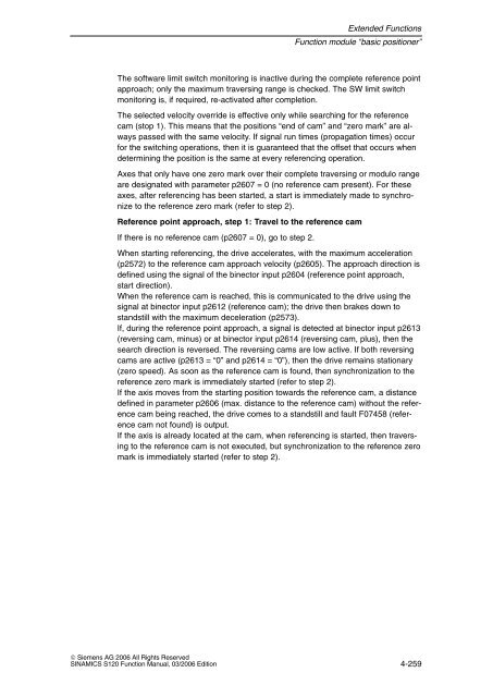
- Page 1:
Function Manual 03/2006 Editionsina
- Page 4 and 5:
Safety information/instructionsThis
- Page 6 and 7:
ForewordTable F-1Useful phases and
- Page 8 and 9:
ForewordTechnical supportIf you hav
- Page 10 and 11:
ForewordESD information!CautionAn e
- Page 12 and 13:
Foreword!Caution The surface temper
- Page 14 and 15:
Table of Contents3.1.10 Sensorless
- Page 16 and 17:
Table of Contents4.24.3 Referencing
- Page 18 and 19:
InfeedActive Infeed1.1 Active Infee
- Page 20 and 21:
InfeedActive InfeedOperating modes
- Page 22 and 23:
InfeedActive InfeedIdentification m
- Page 24 and 25:
InfeedActive InfeedSwitching off th
- Page 26 and 27:
InfeedActive InfeedExample: setting
- Page 28 and 29:
InfeedSmart InfeedConnection diagra
- Page 30 and 31:
InfeedSmart Infeed1.2.2 Line and DC
- Page 32 and 33:
InfeedSmart InfeedSwitching on the
- Page 34 and 35:
InfeedBasic Infeed1.3 Basic Infeed1
- Page 36 and 37:
InfeedBasic InfeedSwitching on the
- Page 38 and 39:
InfeedLine contactor control1.4 Lin
- Page 40 and 41:
InfeedPre-charging and bypass conta
- Page 42 and 43:
Extended Setpoint ChannelExtended s
- Page 44 and 45:
Extended Setpoint ChannelExtended s
- Page 46 and 47:
Extended Setpoint ChannelExtended s
- Page 48 and 49:
Extended Setpoint ChannelExtended s
- Page 50 and 51:
Extended Setpoint ChannelExtended s
- Page 52 and 53:
Extended Setpoint ChannelExtended s
- Page 54 and 55:
Extended Setpoint ChannelExtended s
- Page 56 and 57:
Extended Setpoint ChannelExtended s
- Page 58 and 59:
Extended Setpoint ChannelExtended s
- Page 60 and 61:
Extended Setpoint ChannelExtended s
- Page 62 and 63:
Extended Setpoint ChannelExtended s
- Page 64 and 65:
Extended Setpoint ChannelExtended s
- Page 66 and 67:
Operating ModesServo control3.1 Ser
- Page 68 and 69:
Operating ModesServo controlFunctio
- Page 70 and 71:
Operating ModesServo controlParamet
- Page 72 and 73:
Operating ModesServo controlOFF res
- Page 74 and 75:
Operating ModesServo control3.1.5 T
- Page 76 and 77:
Operating ModesServo controlFixed a
- Page 78 and 79:
Operating ModesServo controlActivat
- Page 80 and 81:
Operating ModesServo control3.1.6
- Page 82 and 83:
Operating ModesServo controlOvervie
- Page 84 and 85:
Operating ModesServo controlCurrent
- Page 86 and 87:
Operating ModesServo controlLow-pas
- Page 88 and 89:
Operating ModesServo controlBand-st
- Page 90 and 91:
Operating ModesServo controlParamet
- Page 92 and 93:
Operating ModesServo controlStructu
- Page 94 and 95:
Operating ModesServo control3.1.10
- Page 96 and 97:
Operating ModesServo controlSwitcho
- Page 98 and 99:
Operating ModesServo control3.1.11
- Page 100 and 101:
Operating ModesServo controlMotor d
- Page 102 and 103:
Operating ModesServo controlInducti
- Page 104 and 105:
Operating ModesServo controlSynchro
- Page 106 and 107:
Operating ModesServo controlMotor M
- Page 108 and 109:
Operating ModesServo controlExample
- Page 110 and 111:
Operating ModesServo control!Warnin
- Page 112 and 113:
Operating ModesServo controlTable 3
- Page 114 and 115:
Operating ModesServo controlDescrip
- Page 116 and 117:
Operating ModesServo controlFunctio
- Page 118 and 119:
Operating ModesServo controlSignal
- Page 120 and 121:
Operating ModesServo controlParamet
- Page 122 and 123:
Operating ModesVector control3.2 Ve
- Page 124 and 125:
Operating ModesVector controlfStart
- Page 126 and 127:
Operating ModesVector control3.2.3
- Page 128 and 129:
Operating ModesVector controlParame
- Page 130 and 131:
Operating ModesVector controlExampl
- Page 132 and 133:
Operating ModesVector control3.2.5
- Page 134 and 135:
Operating ModesVector controlNoteTh
- Page 136 and 137:
Operating ModesVector control3.2.6
- Page 138 and 139:
Operating ModesVector controlKpTnSp
- Page 140 and 141:
Operating ModesVector controlParame
- Page 142 and 143:
Operating ModesVector controlThese
- Page 144 and 145:
Operating ModesVector controlDescri
- Page 146 and 147:
Operating ModesVector controlParame
- Page 148 and 149:
Operating ModesVector control3.2.11
- Page 150 and 151:
Operating ModesVector controlIn add
- Page 152 and 153:
Operating ModesVector controlCarryi
- Page 154 and 155:
Operating ModesVector control3.2.12
- Page 156 and 157:
Operating ModesVector controlIntegr
- Page 158 and 159:
Operating ModesVector V/f control (
- Page 160 and 161:
Operating ModesVector V/f control (
- Page 162 and 163:
ÇÇÇÇÇÇÇÇÇÇÇÇÇÇÇÇÇ
- Page 164 and 165:
Operating ModesVector V/f control (
- Page 166 and 167:
Operating ModesVector V/f control (
- Page 168 and 169:
Operating ModesVector V/f control (
- Page 170 and 171:
Operating ModesInformation on commi
- Page 172 and 173:
Operating ModesInformation on commi
- Page 174 and 175:
Operating ModesInformation on commi
- Page 176 and 177:
Operating ModesInformation on commi
- Page 178 and 179:
Extended Functions“Technology con
- Page 180 and 181:
Extended Functions“Technology con
- Page 182 and 183:
Extended Functions“Technology con
- Page 184 and 185:
ÑÑÑÑÑÑÑÑÑÑÑÑExtended Fu
- Page 186 and 187:
Extended FunctionsSimple brake cont
- Page 188 and 189:
Extended FunctionsSimple brake cont
- Page 190 and 191:
Extended Functions“Extended brake
- Page 192 and 193:
Extended Functions“Extended brake
- Page 194 and 195:
Extended Functions“Extended brake
- Page 196 and 197:
Extended FunctionsAutomatic restart
- Page 198 and 199:
Extended FunctionsAutomatic restart
- Page 200 and 201:
Extended FunctionsFunction module,
- Page 202 and 203:
Extended FunctionsFunction module,
- Page 204 and 205:
Extended FunctionsRedundant operati
- Page 206 and 207:
Extended FunctionsTechnology functi
- Page 208 and 209: Extended FunctionsMotor changeoverO
- Page 210 and 211: Extended FunctionsMotor changeoverT
- Page 212 and 213: Extended FunctionsMotor changeoverT
- Page 214 and 215: Extended FunctionsSimulation mode (
- Page 216 and 217: Extended FunctionsParking axis and
- Page 218 and 219: Extended FunctionsBoot with partial
- Page 220 and 221: Extended FunctionsBoot with partial
- Page 222 and 223: Extended Functionsdv/dt filter plus
- Page 224 and 225: Extended FunctionsFlying restart (v
- Page 226 and 227: Extended FunctionsArmature short-ci
- Page 228 and 229: Extended FunctionsArmature short-ci
- Page 230 and 231: Extended FunctionsSwitching-in a dr
- Page 232 and 233: Extended Functions“Braking Module
- Page 234 and 235: Extended FunctionsFunction module
- Page 236 and 237: Extended FunctionsFunction module p
- Page 238 and 239: Extended FunctionsFunction module p
- Page 240 and 241: Extended FunctionsFunction module p
- Page 242 and 243: Extended FunctionsFunction module p
- Page 244 and 245: Extended FunctionsFunction module p
- Page 246 and 247: Extended FunctionsFunction module p
- Page 248 and 249: Extended FunctionsFunction module
- Page 250 and 251: Extended FunctionsFunction module
- Page 252 and 253: Extended FunctionsFunction module
- Page 254 and 255: Extended FunctionsFunction module
- Page 256 and 257: Extended FunctionsFunction module
- Page 260 and 261: Extended FunctionsFunction module
- Page 262 and 263: Extended FunctionsFunction module
- Page 264 and 265: Extended FunctionsFunction module
- Page 266 and 267: Extended FunctionsFunction module
- Page 268 and 269: Extended FunctionsFunction module
- Page 270 and 271: Extended FunctionsFunction module
- Page 272 and 273: Extended FunctionsFunction module
- Page 274 and 275: Extended FunctionsFunction module
- Page 276 and 277: Extended FunctionsFunction module
- Page 278 and 279: Extended FunctionsBypass (vector)Co
- Page 280 and 281: Extended FunctionsBypass (vector)Tr
- Page 282 and 283: Extended FunctionsBypass (vector)4.
- Page 284 and 285: Extended FunctionsBypass (vector)4.
- Page 286 and 287: Extended FunctionsBypass (vector)Ta
- Page 288 and 289: Extended FunctionsBypass (vector)Ov
- Page 290 and 291: Extended FunctionsSynchronization (
- Page 292 and 293: Extended FunctionsTerminal Module 4
- Page 294 and 295: Extended FunctionsTerminal Module 4
- Page 296 and 297: Extended FunctionsChanging over uni
- Page 298 and 299: Extended FunctionsApplication examp
- Page 300 and 301: Extended FunctionsApplication examp
- Page 302 and 303: Extended FunctionsPosition tracking
- Page 304 and 305: Extended FunctionsPosition tracking
- Page 306 and 307: Basic Information about the Drive S
- Page 308 and 309:
Basic Information about the Drive S
- Page 310 and 311:
Basic Information about the Drive S
- Page 312 and 313:
Basic Information about the Drive S
- Page 314 and 315:
Basic Information about the Drive S
- Page 316 and 317:
Basic Information about the Drive S
- Page 318 and 319:
Basic Information about the Drive S
- Page 320 and 321:
Basic Information about the Drive S
- Page 322 and 323:
Basic Information about the Drive S
- Page 324 and 325:
Basic Information about the Drive S
- Page 326 and 327:
Basic Information about the Drive S
- Page 328 and 329:
Availability of SW FunctionsTable A
- Page 330 and 331:
Availability of SW FunctionsTable A
- Page 332 and 333:
List of AbbreviationsAbbreviation G
- Page 334 and 335:
List of AbbreviationsAbbreviation G
- Page 336 and 337:
List of AbbreviationsAbbreviation G
- Page 338 and 339:
List of AbbreviationsNotesB-338© S
- Page 340 and 341:
ReferencesInteractive catalogs/CA01
- Page 342 and 343:
References/PFT6S/SINAMICS Synchrono
- Page 344 and 345:
ReferencesNotesC-344© Siemens AG 2
- Page 346 and 347:
IndexExtended torque control, 3-80F
- Page 348 and 349:
IndexTorque control, 3-137Extended,
- Page 351 and 352:
Overview of SINAMICS Documentation


