phase 4 report - DNV
phase 4 report - DNV
phase 4 report - DNV

You also want an ePaper? Increase the reach of your titles
YUMPU automatically turns print PDFs into web optimized ePapers that Google loves.
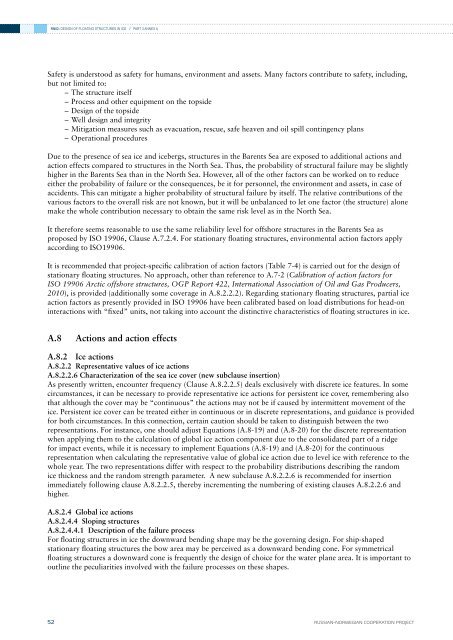
RN02: DESIGN OF FLOATING STRUCTURES IN ICE // PART 3 ANNEX ASafety is understood as safety for humans, environment and assets. Many factors contribute to safety, including,but not limited to:––The structure itself––Process and other equipment on the topside––Design of the topside––Well design and integrity––Mitigation measures such as evacuation, rescue, safe heaven and oil spill contingency plans––Operational proceduresDue to the presence of sea ice and icebergs, structures in the Barents Sea are exposed to additional actions andaction effects compared to structures in the North Sea. Thus, the probability of structural failure may be slightlyhigher in the Barents Sea than in the North Sea. However, all of the other factors can be worked on to reduceeither the probability of failure or the consequences, be it for personnel, the environment and assets, in case ofaccidents. This can mitigate a higher probability of structural failure by itself. The relative contributions of thevarious factors to the overall risk are not known, but it will be unbalanced to let one factor (the structure) alonemake the whole contribution necessary to obtain the same risk level as in the North Sea.It therefore seems reasonable to use the same reliability level for offshore structures in the Barents Sea asproposed by ISO 19906, Clause A.7.2.4. For stationary floating structures, environmental action factors applyaccording to ISO19906.It is recommended that project-specific calibration of action factors (Table 7-4) is carried out for the design ofstationary floating structures. No approach, other than reference to A.7-2 (Calibration of action factors forISO 19906 Arctic offshore structures, OGP Report 422, International Association of Oil and Gas Producers,2010), is provided (additionally some coverage in A.8.2.2.2). Regarding stationary floating structures, partial iceaction factors as presently provided in ISO 19906 have been calibrated based on load distributions for head-oninteractions with “fixed” units, not taking into account the distinctive characteristics of floating structures in ice.A.8 Actions and action effectsA.8.2 Ice actionsA.8.2.2 Representative values of ice actionsA.8.2.2.6 Characterization of the sea ice cover (new subclause insertion)As presently written, encounter frequency (Clause A.8.2.2.5) deals exclusively with discrete ice features. In somecircumstances, it can be necessary to provide representative ice actions for persistent ice cover, remembering alsothat although the cover may be “continuous” the actions may not be if caused by intermittent movement of theice. Persistent ice cover can be treated either in continuous or in discrete representations, and guidance is providedfor both circumstances. In this connection, certain caution should be taken to distinguish between the tworepresentations. For instance, one should adjust Equations (A.8-19) and (A.8-20) for the discrete representationwhen applying them to the calculation of global ice action component due to the consolidated part of a ridgefor impact events, while it is necessary to implement Equations (A.8-19) and (A.8-20) for the continuousrepresentation when calculating the representative value of global ice action due to level ice with reference to thewhole year. The two representations differ with respect to the probability distributions describing the randomice thickness and the random strength parameter. A new subclause A.8.2.2.6 is recommended for insertionimmediately following clause A.8.2.2.5, thereby incrementing the numbering of existing clauses A.8.2.2.6 andhigher.A.8.2.4 Global ice actionsA.8.2.4.4 Sloping structuresA.8.2.4.4.1 Description of the failure processFor floating structures in ice the downward bending shape may be the governing design. For ship-shapedstationary floating structures the bow area may be perceived as a downward bending cone. For symmetricalfloating structures a downward cone is frequently the design of choice for the water plane area. It is important tooutline the peculiarities involved with the failure processes on these shapes.52RUSSIAN–NORWEGIAN COOPERATION PROJECT

![Risk Based Pipeline Integrity Management [Compatibility Mode] - DNV](https://img.yumpu.com/50424229/1/190x146/risk-based-pipeline-integrity-management-compatibility-mode-dnv.jpg?quality=85)