download - Scotty Tele-Transport Corporation
download - Scotty Tele-Transport Corporation
download - Scotty Tele-Transport Corporation
- No tags were found...

Create successful ePaper yourself
Turn your PDF publications into a flip-book with our unique Google optimized e-Paper software.
Table of ContentsTable of Contents1 Welcome.............................................................................................11.1 Welcome..............................................................................................................11.2 Customer Support................................................................................................21.3 The SCOTTY APL-B System.............................................................................31.3.1 Operating and Storage conditions...............................................................41.3.2 Weight and Measurement ...........................................................................42 Setting Up the System.......................................................................52.1 Setting Up the System.........................................................................................52.1.1 APL-B System.............................................................................................52.1.2 Antenna System ..........................................................................................62.1.3 Packing and <strong>Transport</strong> ................................................................................72.2 Power...................................................................................................................72.3 Interface Patch Panel...........................................................................................82.3.1 Satellite Terminals ......................................................................................92.3.2 SCOTTY I-Split Adapter ............................................................................92.3.3 Analog Voice/Fax Interfaces ....................................................................102.3.4 VTC Video/Audio Interfaces....................................................................102.3.5 Configuration and Control Interfaces .......................................................112.3.6 Setting the D-Channel Protocol ................................................................122.4 Synchronous Interfaces Panel ...........................................................................132.4.1 Adtran ISDN Terminal Adapter................................................................142.4.2 Synchronous Interfaces and Crypto Bay...................................................142.4.3 SCOTTY Network Interface.....................................................................152.4.4 SCOTTY I-Sync Adapter..........................................................................152.5 Non Classified Connections..............................................................................162.5.1 Video Conference .....................................................................................162.5.2 Internet/Intranet Access ............................................................................162.5.3 Analog Phone and Fax ..............................................................................162.6 Classified Connections using KIV-7.................................................................172.6.1 Adtran Setup and Operation......................................................................172.6.2 KIV-7 Setup ..............................................................................................192.6.3 Default Setup and Usage...........................................................................212.6.4 I-Sync Setup ..............................................................................................232.6.5 Additional 64k ISDN DTE Setup .............................................................232.6.6 64k and 2x64k ISDN DTE Device Setup..................................................252.6.7 ISDN DTE Video Conference ..................................................................282.6.8 Internet/Intranet Access ............................................................................282.6.9 Phone/Fax Devices with “Magic Voice” ..................................................292.6.10 Analog Phone and Fax ............................................................................292.6.11 VTC Connections with External Bonding Device..................................30SCOTTY APL-B Users' Manuali
Table of Contents2.7 Classified Connections using STE ................................................................... 312.7.1 STE Configuration ................................................................................... 322.7.2 Operation .................................................................................................. 342.8 LAN/WAN Connections .................................................................................. 352.8.1 H.323 Gatekeeper Setup........................................................................... 352.9 The Configuration Utility................................................................................. 362.9.1 The "Setup" - Tab..................................................................................... 362.9.2 The "Equipment" - Tab ............................................................................ 362.9.3 The "ISDN Interface" - Tab...................................................................... 372.9.4 The "Shortcuts" – Tabs............................................................................. 383 First Steps........................................................................................413.1 First Steps ......................................................................................................... 413.2 Starting the SCOTTY <strong>Tele</strong>porter ..................................................................... 413.3 The Main Window............................................................................................ 423.4 Making a Video Call......................................................................................... 423.5 Checking or Editing a Phone Book Entry......................................................... 423.6 Creating a New Phone Book Entry................................................................... 433.7 Receiving a Call................................................................................................ 433.8 Terminating a Call............................................................................................ 433.9 Transfer of Files with Automatic Hang Up...................................................... 443.10 Transfer of Files during a Video Call............................................................. 443.11 Opening a Data Conference............................................................................ 453.12 Making a Still of the Video ............................................................................ 453.13 Controlling the Local Camera ........................................................................ 453.14 Controlling the Far End Camera..................................................................... 463.15 Turning Off the System .................................................................................. 464 SCOTTY Details ...............................................................................474.1 SCOTTY Details .............................................................................................. 474.2 The Main Window............................................................................................ 484.2.1 The Standard Toolbar............................................................................... 484.2.2 Camera Control, Controlling the Camera................................................. 494.2.3 Audio, Controlling the Audio System...................................................... 504.3 The File Menu .................................................................................................. 514.3.1 Dial, Making a Call .................................................................................. 514.3.2 Creating or Modifying a <strong>Tele</strong>phone Book Entry...................................... 534.3.3 Format for Entering the <strong>Tele</strong>phone Number ............................................ 544.3.4 Disconnect, Terminating a Call................................................................ 554.3.5 File Transfer, Transfer Files Efficiently................................................... 554.3.6 Share, Starting the Data Package.............................................................. 574.3.7 Snapshot, Taking a Still Picture ............................................................... 574.3.8 Far End Cam Ctrl, Controlling a Far End Camera ................................... 574.3.9 Exit, Ending the Program ......................................................................... 574.4 The View Menu................................................................................................ 584.4.1 Video Window, Manipulating the Video Window .................................. 584.4.2 Camera Control, Activating the Camera Toolbar..................................... 594.4.3 Tone Pad, Playing DTMF Tones.............................................................. 594.4.4 Local Camera Control, Controlling the Local Camera ............................ 594.4.5 Far End Camera Control, Controlling the Far End Camera ..................... 614.4.6 Audio & Video Controls .......................................................................... 634.4.7 Video Switch Matrix ................................................................................ 644.4.8 Audio Switch Matrix................................................................................ 64iiSCOTTY APL-B Users' Manual
Table of Contents4.4.9 Application Examples for the Audio & Video Controls Dialog...............654.4.10 Pic In Pic, Setting the Picture in Picture view ........................................654.4.11 Toolbars, Manipulating the Toolbars......................................................654.4.12 Received Files, Listing the Received Files .............................................664.4.13 Connection Info, Displaying the Connection Status...............................674.5 The Options Menu.............................................................................................694.5.1 Dialing, Setting the Dialing Parameters....................................................694.5.2 Audio, Setting the Audio Levels...............................................................714.5.3 Video, Setting the Video Parameters........................................................724.5.4 Data, Adjusting the Data Channel Parameters..........................................724.5.5 Directories, Setting the SCOTTY Directory Structure.............................744.5.6 Preferences, Setting the System Parameters .............................................744.5.7 File Exchange Server (optional) ...............................................................764.5.8 File Exchange Server, Setup and Operation .............................................774.5.9 Save, Saving the Current Settings.............................................................814.5.10 Factory Defaults, Restoring the Factory Defaults...................................824.6 The Help Menu .................................................................................................834.6.1 HelpTopics, the SCOTTY Help System...................................................834.6.2 Context Help, the Topical Help ................................................................834.6.3 About <strong>Tele</strong>porter, Displaying the SCOTTY Configuration .....................834.7 Shortcuts............................................................................................................844.8 Keyboard Functions ..........................................................................................875 Data Package ...................................................................................895.1 Data Package.....................................................................................................895.2 The Microsoft NetMeeting 3.............................................................................895.2.1 Creating a Data Conference ......................................................................895.2.2 During the Data Conference .....................................................................905.2.3 Handling the Whiteboard..........................................................................916 Glossary ...........................................................................................937 Appendix ..........................................................................................997.1 Application Notes..............................................................................................99SCOTTY APL-B Users' Manualiii
Table of ContentsivSCOTTY APL-B Users' Manual
Chapter 1Welcome1 Welcome1.1 WelcomeWelcome to the world of advanced communication... welcome to the world ofSCOTTY!This manual has been designed to help you take full advantage of yourSCOTTY equipment. It is not only a comprehensive guide to the operation ofthe unit, it also provides technical details, simple step by step instructions onhow to perform the most common applications, and more. We recommend youread this manual carefully in order to fully benefit from SCOTTY's advancedsolutions.The SCOTTY Group manufactures advanced communication devices andsupplies complete solutions for clients around the world. SCOTTY brandproducts include:• Videophones• Video Communication Systems• Mobile Communication Solutions• CareStation for <strong>Tele</strong>health• eyesite Remote Surveillance• Communication EquipmentPlease find detailed information on our website: www.scottygroup.comYour equipment has been manufactured at:SCOTTY <strong>Tele</strong>-<strong>Transport</strong> <strong>Corporation</strong> AGa SCOTTY Group plc companyTeslastrasse 4, 8074 Grambach, AustriaT +43 316 409 426, F +43 316 409 426-53SCOTTY APL-B Users' Manual 1
Welcome Chapter 11.2 Customer SupportContacting SCOTTY's Customer Services & Technical Support:Europe, Middle East, Africa +43 316 409 426support.emea@scottygroup.comThe Americas Atlanta: +1 770 825 0574Wilmington: +1 910 395 6100support.americas@scottygroup.comAsia Pacific +63 2 833 7783support.asiapac@scottygroup.comIf you need urgent help for your SCOTTY solution, call the appropriatecustomer support number for your part of the world:Europe, Middle East, Africa Austria (GMT +1): +43 664 454 2827The Americas Atlanta, USA (GMT -6): +1 770 380 7186Asia Pacific Philippines (GMT +8): +63 917 537 0624Please always include the serial number of your SCOTTY unit.Videoconference test numbersH.320 ISDN numbers (64 kbit/s and 2x64 kbit/s):• Austria: +43 316 407849• USA: +1 770 246 9082• Asia: +63 2 581 1093H.323 IP number (up to 512 kbit/s):• Austria: 193.154.221.1982 SCOTTY APL-B Users' Manual
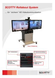
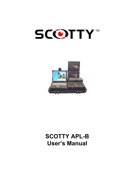
Chapter 1Welcome1.3 The SCOTTY APL-B SystemThe SCOTTY APL-B system is a highly integrated “all in one” communicationunit for VTC, Data and Voice applications. Due to the integrated dockingmodule for encryption devices (KIV-7, OMNI optional) it is an easy to use unitfor all kind of classified applications.The following feature highlights are implemented:• Integrated Notebook (MIL 810 Spec) for video-/data-communication,printing/scanning, satellite modem control/configuration, …• Integrated Inmarsat GAN(M4) “Dual modem” system for 64k and 2x64kcommunication• Integrated satellite channel bundling• Integrated professionl VTC module for call sizes up to 1.152 kbit/saccording to H.320/H.323 standard• Integrated high efficient “File Transfer” function with channel bundlingand append function• Integrated Printer/Scanner device• Integrated synchronous DTE interface for interconnection with encryptiondevices• Two integrated docking slots for encryption devices• All In One Power supply module for AC and DC connectivityThe SCOTTY APL-B system is split into the APL-B hardcase (with handle andwheels) and the APL-B antenna case.The APL-B hardcase consists of the communication module (left side) withnotebook, PC docking unit and interface panel unit and a separate power supplymodule (right side) including a fold up tray for the two integrated Nera satellitemodems.An encryption docking module, housing two independent bays for encryptiondevices, is located on top of the power supply module.The APL-B power supply module supplies all internal components and offers12V and 24V DC outlets for supplying external devices.SCOTTY APL-B Users' Manual 3
Welcome Chapter 1Both modules, the communication module and the power supply module, aremounted on shock absorbing rubber mounts. Additional foam inlets in theupper case hood protect the APL-B components during transport.1.3.1 Operating and Storage conditionsThe operating and storage conditions of the SCOTTY APL-B system arelimited to the use of a notebook PC with TFT display and the printer/scannercombination.Operating Temperatures:APL-B: 23°F - 113°FAntenna Outdoor unit: -13°F - 131°FStorage / <strong>Transport</strong> Temperatures:APL-B -4°F - 131°FAntenna Outdoor unit. -58°F- 176°FHumidity:Operation: 80%Storage/<strong>Transport</strong>: 95%1.3.2 Weight and MeasurementAPL-B Communication Case:Antenna Box:88.2 lbs., W=29”, D=20”, H=8”52.9 lbs., W=24”, D=24”, H=10”4 SCOTTY APL-B Users' Manual
Chapter 2Setting Up the System2 Setting Up the System2.1 Setting Up the System2.1.1 APL-B System• Unpack, unfold the satellite modem tray and remove the foam inlets• Connect the USB printer cable• Open the notebook and fold the video camera, mounted on the display ofthe notebook, into operating position. Be sure the camera is connected tothe appropriate connector (see picture)• All accessories included with the APL-B can be stowed in the accessorystow box on the inside of the APL-B case• If needed, connect the headset to Audio In 2 and Audio OutSCOTTY APL-B Users' Manual 5
48 THE SAGE HANDBOOK OF SOCIAL WORK RESEARCHexample professional networks, continuingprofessional development and staffexchanges.It is now more widely accepted that evidencewill never be capable of replacing professionaljudgment, particularly forprofessionals tasked with complex decisionmaking in the inherently risky situationsencountered by social workers every day.However, for evidence to support the professionaljudgment in, for example, the managementof cases and resources and for evidenceto enable practitioners to think differentlyabout the challenges that face them, it willneed to enhance skills and understandingrather than undermine them. Thus there remainchallenges for organizations, individuals andthe profession more widely if evidence is to beused actively and intelligently in decisionmaking.There is still a challenge in providing moreobjective, impartial evidence throughimprovements in the quality and synthesis ofevidence. In particular, the role of systematicreviews as rigorous syntheses to informpractice has been promoted and supportedthrough the Campbell Collaboration socialwelfare group. Ventures such as theCampbell Collaboration reflect the internationaldemand for objective, rigorous evidenceto support policy and practice. Thenext step will be to ensure that this evidencemakes a meaningful contribution to socialwork practice.5314-Shaw-02.indd 485/13/2009 10:59:13 AM
Chapter 2Setting Up the System2.1.3 Packing and <strong>Transport</strong>• Before closing the APL-B communication case the foam inlets have to beplaced between the printer/crypto docking bay and the satellite modem traywhich has to be folded into a horizontal position• In order to avoid damaging the USB printer cable, the cable has to bedisconnected before closing the APL-B case• Close the Notebook. The video camera, mounted on the display of thenotebook, has to be folded back into the transport position• All accessories can be stowed in the accessory stow box on the inside ofthe APL-B case. Be aware that the cover of the stow box is locked with thebolt• For proper protection during transport the antenna units have to betransported in the original SCOTTY boxes and the foam inlets have to bein place between the antenna panels2.2 PowerThe SCOTTY APL-B can be powered by 88 to 264 volts AC, 47 to 63 Hz, or19 to 36 volts DC. The sockets are located on the right side of the system (seethe label below the socket).The system is started by activating the power switch. The system automaticallyadjusts to the power source.For external devices, the APL-B power supply unit offers two different DCoutlets, one at 12V/8A and the other at 24V/6A.The user need not worry about the power source. The SCOTTY APL-B system can adapt topractically every AC utility power in the world and many DC power sources, for exampleship or car battery without an outside convertor- even mixing up the polarity will notdamage the system.If desired, the system can be connected to both AC and DC power sources simultaneously.In this case, the SCOTTY APL-B System is powered by the AC power but will automaticallyswitch to the DC power on the fly if the AC power is interrupted - for example in the case ofa power outage.Only the NWC’s and the Laptop can be powered by their internal batteries.SCOTTY APL-B Users' Manual 7
Setting Up the System Chapter 22.3 Interface Patch PanelThe APL-B interface panel behind the Notebook computer offers a variety ofISDN and analog Voice/Fax interface connectors with the flexibility to “patch”the configuration according to the desired network interconnection (see picturebelow).ADTRAN ISU 2x64I-SPLITVCPCA/BI-SYNCThe ISDN plugs are arranged “top-down” starting with the two ISDN SAT 1and SAT 2 outlets of the satellite modems from top.The APL-B has an integrated SCOTTY I-Split adapter offering a standardISDN S0 NT network outlet “S0 I-Split” which, for convenience, is availabletwice on the patch panel. The I-Split combines the ISDN data streams of thetwo satellite terminals SAT 1 and SAT 2.The “S0 Adtran” input connector can be hooked up to an I-Split outlet ordirectly to one of the satellite terminal outlets SAT 1 /SAT 2 using the ISDNpatch cables. It can also be connected to an external ISDN-outlet.The “S0 I-Sync” ISDN NT outlet, which is available twice, can be patched toISDN application inputs S0 1, S0 2 or S0 (A/B) or any other externalcommunication device using ISDN as a network interface.The “S0 1” ISDN input is typically used for ISDN connections with theintegrated “<strong>Tele</strong>port” VTC application. It can be used alternatively forapplications using the integrated ISDN network interface adapter.8 SCOTTY APL-B Users' Manual
Chapter 2Setting Up the SystemThe “S0 2” connector is an ISDN input which can be used for applicationsusing the integrated ISDN network interface adapter. Software for e-mail,Internet access, ftp <strong>download</strong>, remote server access, fax… is already installed.The “<strong>Tele</strong>port 2xISDN” shortcut uses both S0 plugs for 2x64kbit/sconnections.The A/B “S0” plug, in conjunction with the two A/B interfaces 1 and 2, offersthe possibility to use external analog phone/fax equipment.2.3.1 Satellite TerminalsThe SCOTTY APL-B system has two fully integrated Nera Inmarsat GAN(M4) terminals. The GAN terminals are fully supplied by the APL-B powersupply module or, for emergency use, they can be operated from the internalbatteries.GAN services are:56/64k UDI Data data56/64k Speech voice or analog fax3,1 kHz Audio analog fax4,8k Voice compressed voiceMPDSmobile packet data serviceFor classified applications (VTC, data transfer, ftp <strong>download</strong>, mail service,magic voice etc.) with encryption devices, the Inmarsat UDI data service at56/64k is the main service in use.Further details on how to operate and configure the NERA satellite GANmodems can be found in the “NWC Getting Started” manual.2.3.2 SCOTTY I-Split AdapterThe built-in SCOTTY I-Split adapter is linking the two independent single B-channel ISDN interfaces of the two satellite terminals together to a fullycompliant S0 ISDN NT interface offering 2 B-channels. The I-Split adapterhandles the independent clock signals of the two terminals by using severalinternal FIFO data buffers in order to deliver a stable, single clock ISDN NTinterface.SCOTTY APL-B Users' Manual 9
Setting Up the System Chapter 22.3.3 Analog Voice/Fax InterfacesThe fully integrated TA adapter, converting two independent analog inputs A/B1 and A/B 2 into a single S0 ISDN interface, allows the operation of analogphone/fax equipment directly on the APL-B.It might be useful to assign ISDN MSN (multiple subscriber numbers) to theanalog ports. These MSNs are used by the Inmarsat modems to select theInmarsat service. Furthermore the SCOTTY I-Sync adapter with “MagicVoice” uses MSNs for PBX functionality (see chapter SCOTTY I-SyncAdapter)The MSN assignment can be programmed using a simple analog phone:FUNCTIONKEY INClear default settings on both ports * 93 * #Program MSN on TEL 1* 93 * 1 #(e.g. 20)* 90 * 20 #Program MSN on TEL 2* 93 * 2 #(e.g. 30)* 90 * 30 #The default assignment and usage for the phone ports is:TEL 1: MSN 20 SpeechTEL 2: MSN 30 Fax2.3.4 VTC Video/Audio InterfacesAll analog video and audio interfaces of the integrated SCOTTY H.320/H.323videoconferencing module are available on the interface patch panel (VC onlower right corner). The VTC module offers two video inputs, one videooutput, two audio inputs and one audio output. The connectors are assigned asfollows:10 SCOTTY APL-B Users' Manual
Chapter 2Setting Up the SystemVideo IN 1:Video IN 2:Video OUT:Composite video input, NTSC; shared with notebook cameraS-Video input, NTSCComposite video output, NTSCAudio IN 1:Audio IN 2:Audio OUT:LINE inputMIC/Line input; used for the headset microphoneLINE output; used for the headset speakers.2.3.5 Configuration and Control InterfacesA number of configuration interfaces for the different integrated componentsare available on the interface patch panel:PC COM: The RS232 COM1 port of the notebook PC is available on theinterface patch panel. A short RS232 Nullmodem patch cable (included in theAPL-B cable delivery) can be used to interconnect with other RS232 controlinterfaces on the interface panel. The necessary Hyperterminal application icon“9600 Baud” is already available on the Windows desktop.ADTRAN ISU 2x64: The integrated Adtran 2x64 terminal adapter can beconfigured and controlled by using the keypad. Advanced setup and control canbe done using the RS232 Config port.CONFIG I-Split and CONFIG I-Sync: All major status information, likePWR, NT module ready (NT), physical layer activated (PH), dialing (CN isflashing) or connected (CN is ON), is displayed directly by the LED´s of theunits. More status information or maintenance functions and software upgradescan be executed using the CONFIG ports for each SCOTTY I-Adapter.COM SAT 1 and SAT2: These two interfaces are connected from the controlports of the satellite GAN modem units. By using the SCOTTY RS232Nullmodem cable between the PC COM port and one of these interfaces, eachNera GAN modem can be configured using the “VtLite” application software.For further information on the VtLite software please see the “NWC GettingStarted” manual.SCOTTY APL-B Users' Manual 11
Setting Up the System Chapter 22.3.6 Setting the D-Channel ProtocolOn default, all ISDN interfaces are set to Euro-ISDN.The S0 1 and S0 2 plugs are connected to the integrated ISDN card and can beused by the <strong>Tele</strong>porter application and other applications (Internet access,Fax…). The ISDN protocol can be configured with these steps:• Start | Settings | Control Panel• Doubleclick System• Select Hardware folder and choose Device Manager buttonOpen the Network adapter list and select the Digi DataFire QuadMicro with•the right mouse button• select Properties and choose the ISDN Folder• Select the correct "D-Channel Protocol"• SPIDS or MSN can be configured with the Configure button.12 SCOTTY APL-B Users' Manual
Chapter 2Setting Up the System2.4 Synchronous Interfaces PanelThe SCOTTY APL-B system offers a variety of synchronous interfaces on theleft side panel of the communication module (left module). Similar to theinterface patch panel, the interfaces are arranged in two rows top-down startingwith the communication network side via the encryption interfaces down to theapplication network interface.ADTRAN PORT 2ADTRAN PORT 1BAY 1-BLKBAY 2-BLKBAY 1-REDBAY 2-REDBAY 1-REDI-SYNC PORT 1I-SYNC PORT 2SCOTTY NETWORKSynchronous Interfaces PanelThe plugs in the left row are associated with the first “encryption bay”, theright row to the second “encryption bay”. Due to the Adtran’s characteristics,Adtran Port 2 and Port 1 are reversed.For convenience, a special SCOTTY “APL-B Network Plug” can be usedinstead of network cables for most applications (see picture).Usage of Network PlugsSCOTTY APL-B Users' Manual 13
Setting Up the System Chapter 22.4.1 Adtran ISDN Terminal AdapterThe Adtran ISU 2x 64k ISDN terminal adapter offers two independent RS530standard network interface ports (DCE). Depending on the configuration, theunit can be operated on two independent single 64 kbit/s ports or on one single128 kbit/s port with Bonding Mode 1 channel aggregation. As the Adtran unitroutes incoming ISDN calls automatically to the RS530 Port 2, the interfaceport 2 is in line (left row) with the connectors of crypto bay 1 and the SCOTTYNetwork. Single channel 64k or 128k Bonding calls can be handled with thissetup without changing the interconnection between the interfaces of the leftrow.Specific Adtran configuration settings for different applications and networkspeeds together with the KIV-7 secure applications will be outlined later in themanual.2.4.2 Synchronous Interfaces and Crypto BayThe SCOTTY APL-B system offers two independent “Crypto Bays” forimplementing encryption devices like KIV-7 or OMNI directly into the setup.The “double” bay setup gives more flexibility (and backup) to the user as twoindependent encryption devices (also mixed KIV-7 and OMNI setup) can beused at the same time for two different applications (e.g.: single channel VTCat 64k via bay 1 and at the same time a 64k connection via bay 2 for a serverconnection).The KIV-7 device is directly powered from the APL-B power module via thecrypto bay back panel. The BLACK and RED interfaces of the two crypto baysare wired directly to the RS530 interface connectors on the left side panel ofthe APL-B communication module. With the “APL-B Network Plug”, theBLACK interface is interconnected with the ADTRAN (Port 2) and a secondPlug is used to interconnect the RED interface with the SCOTTY Network. Nofurther cabling is required.14 SCOTTY APL-B Users' Manual
Chapter 2Setting Up the System2.4.3 SCOTTY Network InterfaceThe SCOTTY Network interface (DTE) is connected to the SCOTTY VTCmodule of the APL-B. The 25-pin D-type connector interface is very flexibleand offers DTE configurations according to RS530, EIA530A, RS232 (V.24),V.35, X.21, RS449 standards. Furthermore V.25bis, X.21, Dial on DTR dialingprotocols are supported. The appropriate SCOTTY Network setup isautomatically loaded by the corresponding SCOTTY <strong>Tele</strong>port application icon.The SCOTTY VTC module offers data rates of 64 kbit/s up to 1.152 kbit/s inH.320 mode via the SCOTTY Network interface.2.4.4 SCOTTY I-Sync AdapterThe SCOTTY I-Sync adapter is a very unique device which converts twoindependent synchronous DTE ports into one single ISDN NT network output.This function enables standard ISDN applications to interconnect with the REDinterface side of the encryption device. In many cases it is the missing linkbetween the application and the encryption device.Furthermore the I-Sync adapter can support transcoding of the ISDN dialinginto an appropriate dialing protocol like V.25bis, X.21 or Dial on DTR on thesynchronous DTE network for both channels independently.Another unique option of the I-Sync adapter is the “Magic Voice” functionwhich enables the user to operate standard phone/fax devices connected to theI-Sync adapter (also via the A/B TA) to be used in conjunction with “data only”encryption devices (e.g.: KIV-7). For the “Magic Voice” functionality, thesame type of I-Sync adapter is necessary on the remote end of the classifiedconnection, as the I-Sync adapters need to exchange a protocol over the link.The “Magic Voice” function can also transfer a two digit phone numberextension from the dialing end to the remote end. At the remote end thereceiving I-Sync extracts this extension number from the protocol and outputsit as a MSN to all connected ISDN devices. Only the phone/fax device with thematching stored MSN number will ring on this incoming call.SCOTTY APL-B Users' Manual 15
Setting Up the System Chapter 22.5 Non Classified ConnectionsFor non classified applications, the ISDN device can be directly patched to theSCOTTY I-Split ISDN network outlet. By dialing up one or two channels, theapplications can be operated in 64k or 2x64k call sizes. Furthermore, twodifferent applications can be patched in parallel to the I-Split adapter operatingat 64k each (e.g.: VTC at 64k in parallel with phone call).Alternatively, ISDN devices can be connected directly to the satellite modemsusing ISDN SAT 1 and ISDN SAT 2.2.5.1 Video ConferenceFor a non classified ISDN VTC application connect “S0-1” with “S0 I-Split”.A doubleclick on the pre-defined "<strong>Tele</strong>port" icon starts the software. Byselecting an entry from the phone book and choosing the "Dial" button a 2x64kcall is performed. Pressing "Low Cost" dials a 1x64k connection. By selecting"Use 00 as Prefix (Satellite-Style Dialing)" in the dialog Options | Dialing, thedesired phone number is automatically converted into a satellite-compatiblestyle.2.5.2 Internet/Intranet AccessFor Internet or Intranet access, configure a dial-up Internet connection inWindows “Network and Dial-up Connections”, using the WAN Miniportdriver for ISDN port 2. Using channel aggregation (called “multi-link”), accesswith 2x64kbit/s is possible.Connect “S0-2” with “S0 I-Split”. A doubleclick on the prepared dial-up setupopens the connection, which can be used by any Windows application likeInternet Explorer, Outlook Express…2.5.3 Analog Phone and FaxConnect “A/B S0” with “S0 I-Split”. Connect the analog equipment to “A/B 1”and “A/B 2”.Using the default configuration, “A/B 1” can be used for compressed speech(MSN 20), “A/B 2” for uncompressed speech and Fax (MSN 30).16 SCOTTY APL-B Users' Manual
Chapter 2Setting Up the System2.6 Classified Connections using KIV-7The SCOTTY APL-B system, with its flexible network architecture, offers awide range of connectivity to different encryption devices. In the followingchapters, application setups for classified connections using KIV-7HS aredescribed. These can also be used for the OMNI encryption device.2.6.1 Adtran Setup and OperationThe basic setup of the Adtran unit has to be carried out only once. After this,only a few configuration changes are needed to switch from setup to setup asdescribed in the following chapters.For Adtran configuration, connect “PC Com” with “Adtran Config” and openthe Hyperterm “9600 Baud” shortcut. Enter following sequence:• Enter !V to enter menu mode• Press Ctrl+C to view the Configuration MenuConfigure dte #2: (press Ctrl+P to change dte port if needed)• Perform Quick Setup with Dial 128kOnly if DTR is passed through the KIV-7, set DTR Options to Idle when off.•In case of doubt leave setting to Ignore DTR• Set TXINIT to 20sSet LDN DTE 2 to the last 9 digits of the 64k data service phone number•from the satellite modem #2 (e.g. 600201234).• Check all other settings according to the following snapshot:Adtran bonding mode setupSCOTTY APL-B Users' Manual 17
Setting Up the System Chapter 2Configure dte #1: (Press Ctrl+P to change dte port)• Perform Quick Setup with Dial 64k• Set DTR Options to Off>On dial #0• Set LDN DTE 1 to exactly(!) the same number as used for LDN DTE 2• Check all other settings according to the following snapshot:1Adtran clear-channel mode setupThe Hyperterm connection can also be used for dialing (Ctrl+D) and statusmonitoring (Ctrl+V). The dte port can be switched inside the menus by pressingCtrl+P.For classified operation, the config cable should be disconnected. Dialing andstatus monitoring can be done using the integrated keypad and display.18 SCOTTY APL-B Users' Manual
Chapter 2Setting Up the System2.6.2 KIV-7 SetupThe SCOTTY APL-B system can operate two independent classifiedconnections using two KIV-7 encryption devices. The most common setup withthe KIV-7 is to operate one device at a call size of 64 k or at 128k.For using the KIV-7 encryption device directly in the APL-B setup togetherwith the “Crypto Bay” the KIV-7 unit has to be mounted into the KIV-7 tray(four screws are attached).In order to eliminate the slight connector position variations (connectorpositions are slightly different on each device) of the KIV-7 D-type connectorson the back panel of the device, SCOTTY has attached a special short bolt (twoper connector) to be screwed into the hexagons of each D-connector on theKIV-7. These bolts guide the KIV-7 tray into the D-connectors of the APL-Bcrypto docking station.Placing SCOTTY bolts into KIV-7 connectorsSCOTTY APL-B Users' Manual 19
Setting Up the System Chapter 2The following settings should be made to the standard factory default setup:Setup AClkSel MASTERSynSel REDCommSel FDXDataMod BBDataLen SYNCH/STX Rate EXT DRCRX Rate EXT DRCTTY Mode AUTOI/Fctrl no selectionSetup BInvert no selectionTX Clock contTXC*RX Clock contRXCSyncOOS DisabledIdleSel DisabledAutoPhs OFFUpdateU EnabledClkLock DisabledSetup CRED I/F EIA-530BLK I/F EIA-530FIL I/F 102 / STDFILaddr 254RCUaddr 31Setup DMstrSlv SLAVEAlgrthm ALG 1This setup should then be permanently saved on the device.NOTES: Be sure the same key is used on the KIV-7HS units at both ends of thecommunication. Different versions of KIV-7HS might have compatibilityissues, they seem to synchronize but will not pass useful data. In this case, tryusing the same version of KIV-7HS at both ends, i.e., KIV-7HS to KIV-7HS orKIV-7HSB to KIV-7HSB.20 SCOTTY APL-B Users' Manual
Chapter 2Setting Up the System2.6.3 Default Setup and UsageThis setup is for outgoing and incoming video conferencing, including filetransfer and data sharing, at 64k and 128k over KIV #1.Setup:Connect “S0 I-Split” with “S0 Adtran”.Connect “Adtran Port 2” with “Bay 1-BLK” and “Bay 1-RED” with “<strong>Scotty</strong>Network” using two SCOTTY network plugs. The network plugs for bay 2 areunused and can remain in their positions.Insert a KIV-7 unit into bay 1.BAY 1-REDPCA/BDefault SetupAdtran and KIV-7 Configuration:All units remain in default setup (see previous chapters)SCOTTY APL-B Users' Manual 21
Setting Up the System Chapter 2Operation:Start “<strong>Tele</strong>port KIV” application.Dial the connection manually by using the Adtran keypad:• Press 4 (Dial) and Enter• Press 2 (dte #2) and Enter• Press 2 (Dial number) and Enter• Enter the number using the keypad and press EnterThe bonding setup will take place, the <strong>Tele</strong>port application will ring andsynchronize.To redial the last number dialed:• Press 4 (Dial) and Enter• Press 2 (dte #2) and Enter• Press 3 (Redial) and EnterHang-up of the connection can be done manually by using the Adtran keypad:• Press 4 (Dial) and Enter• Press 2 (dte #2) and Enter. For dte #1 just press Enter.• Press 1 (Hangup) and EnterIncoming connections with both 64k and 128k are picked up automatically.The remote side has to dial the phone number of satellite modem #1.When not in a menu, the Adtran display shows the status of the selected port. The port can bechanged using the up and down keys. The message “Disabled” is displayed even if the ISDNline is ready (ISDN power-down mode). If “Link in Sync” appears, disconnect and reconnect“S0 Adtran” to resynchronize.Changing outgoing data rate to 64k:The Adtran must be re-configured using the Adtran keypad or Hyperterm (seechapter Adtran Setup and Operation):• Enter the Config menu for dte #2• Set Bit Rate to 64000• Set Protocol to Clear Channel22 SCOTTY APL-B Users' Manual
Chapter 2Setting Up the SystemTo set the system back to outgoing 128k data rate operation, use the followingAdtran setup:• Enter the Config menu for dte #2• Set Bit Rate to 128000• Set Protocol to Bonding mode 12.6.4 I-Sync SetupWhen using one of the following setups, including the I-Sync adapter, theadapter needs to be configured once.For I-Sync configuration, connect “PC Com” with “I-Sync Config” and openthe Hyperterm “9600 Baud” shortcut. Enter the following sequence:• Press Enter to see the main menu• Choose Configuration (2) and press Enter• Choose Config Ports (2) and press Enter• Choose Port 1 (1) and press Enter. Choose X.21/C and press Enter.• Choose Port 2 (2) and press Enter. Choose X.21/C and press Enter.• Press ESC to get back into the Configuration menu• Choose Config Routing (2) and press Enter.• Choose Port 2, Port 1 (2) and press Enter.• Choose Save (7), press Enter and enter password (iboxx).2.6.5 Additional 64k ISDN DTE SetupThis setup extends the default setup, allowing outgoing and incoming VTC at64k and 128k over KIV #1, with a second path via KIV #2. This second pathallows outgoing Internet access, PC-fax, Magic Voice (ISDN or analog voiceand fax), etc. by using the KIV-7 DTE dial-through technology (requiring thatDTR is passed through the KIV-7 #2).Additional Setup:Connect “Adtran Port 1” with “Bay 2-BLK” and “Bay 2-RED” with “I_SyncPort 2”. Insert a KIV-7 unit into bay 2.Connect “S0 I-Sync” with the desired ISDN device(s):“A/B S0” for “Magic Voice” analog phone and fax.“S0 2” for Internet/Intranet access, PC-faxExternal ISDN equipmentSCOTTY APL-B Users' Manual 23
Setting Up the System Chapter 2BAY 1-REDPCA/BDefault and additional 64k DTE SetupAdtran, KIV-7 and I-Sync Configuration:All units remain in default setup (see previous chapters)Operating outgoing 64k ISDN DTE device connections:This setup supports automatic call control to a pre-programmed phone number(e.g. classified Internet access point) by using the KIV-7 DTE dial-throughtechnology. It can handle outgoing connections only, incoming calls are alwaysrouted to the VTC setup. This mode can be used even if a 64k VTC connectiontakes place in parallel.The phone number to be dialed must be configured once using the Adtrankeypad or Hyperterm (see chapter Adtran Setup and Operation):• Enter the Dial menu for dte #1 (Hyperterm: Ctrl+D and Ctrl+P if needed)• Enter Store/Review menu• Set entry #0 to desired phone numberA connection can be established by dialing any phone number on the ISDNDTE device (e.g. just “1”). The I-Sync activates the DTE line and the Adtrandials a 64k data connection to the stored phone number.The connection can be disconnected by hanging up the ISDN DTE devicewhich originated the call.24 SCOTTY APL-B Users' Manual
Chapter 2Setting Up the System2.6.6 64k and 2x64k ISDN DTE Device SetupThis setup allows outgoing and incoming connections to any ISDN DTEdevices with up to two 64k channels in parallel. It can be used for Internetaccess, PC-fax, Magic Voice (ISDN or analog voice and fax) and all otherexternal ISDN devices. This setup supports automatic call control to a preprogrammedphone number (e.g. secure Internet access point) by using theKIV-7 DTE dial-through technology (requiring that DTR is passed through theKIV-7 #2).As both 64k channels are fully independent and could be used by differentISDN devices at the same time, two KIV-7 units are needed for 2x64koperation. If just 64k connections are used, only a single KIV-7 in bay #1 isneeded.Configuration:Connect “S0 I-Split” with “S0 Adtran”.Connect “Adtran Port 2” with “Bay 1-BLK” and “Bay 1-RED” with “I_SyncPort 1”. Insert a KIV-7 unit into bay 1.Connect “Adtran Port 1” with “Bay 2-BLK” and “Bay 2-RED” with “I_SyncPort 2”. Insert an optionally 2 nd KIV-7 unit into bay 2 for 2x64k operation.Connect “S0 I-Sync” with the desired ISDN device(s):“A/B S0” for magic-voice analog phone and fax.“S0 1” for 1x64k and 2x64k VTC (bonding 128k not supported)“S0 2” for Internet/Intranet access, PC-fax, CAPI applicationsExternal ISDN equipment (Phone, Fax, VTC…)PCA/BSCOTTY NETWORKISDNDepending on applicationSCOTTY APL-B Users' Manual 25
Setting Up the System Chapter 2Adtran Configuration:64k and 2x64k ISDN DTE Device SetupThe configuration of port 2 must be changed from the default setup (see chapterAdtran Setup and Operation) using the keypad or Hyperterm:• Enter the Config menu for dte #2• Set Bit Rate from 12800 to 64000• Set Protocol from Bonding mode 1 to Clear Channel• Set DTR Options from Idle when off to Off>On dial #0To reset the default configuration change the three values back to their originalsettings.I-Sync Configuration:The call routing should be changed (see chapter I-Sync Setup):• Enter the Configuration menu• Choose Config Routing (2) and press Enter.• Choose Port 1, Port 2 (1) and press Enter.• Choose Save (7), press Enter and enter password (iboxx).To reset the default configuration change the routing back to the originalsetting.Phone number setup:The phone number to be dialed must be configured once using the Adtrankeypad or Hyperterm (see chapter Adtran Setup and Operation).Dte #2 is used for the 1 st channel:• Enter the Dial menu for dte #2 (Hyperterm: Ctrl+D and Ctrl+P if needed)• Enter Store/Review menu• Set entry #0 to desired phone numberThe additional 2 nd channel will be dialed using dt2 #1:• Enter the Dial menu for dte #1 (Hyperterm: Ctrl+D and Ctrl+P if needed)• Enter Store/Review menu• Set entry #0 to desired phone number26 SCOTTY APL-B Users' Manual
Chapter 2Setting Up the SystemOperating outgoing connections:A connection can be established by dialing any phone number on the ISDNDTE device (e.g. just “1”). The I-Sync activates the DTE line and the Adtrandials a 64k data connection to the stored phone number of dte #2.A second 64k connection can be dialed at any time in parallel with the sameprocedure. The stored phone number of dte #1 is used.A connection can be disconnected by hanging up the ISDN DTE deviceoriginating the call.Operating incoming connections:Incoming data connections on any satellite modem are received by the Adtranunit, encrypted by the KIV unit #1, and forwarded from the I-Sync to theconnected ISDN DTE device. The ISDN device rings and the user can pick upthe call.If more than one ISDN device is connected, all devices with no configuredMSN number will ring at the same time and the user can choose which picksup the call. Using “Magic Voice”, the remote side can directly dial-through to aspecific device (see chapter Phone/Fax Devices with “Magic Voice”).A second incoming connection can be received using the unused satellitemodem and KIV unit #2.A connection must be disconnected either by the caller, or manually using theAdtran keypad (see chapter Adtran Setup and Operation).If two KIV units are used, mixing an incoming 64k and an outgoing 64kconnection is also possible. Furthermore, the two 64k channels can be used bydifferent ISDN devices in parallel.SCOTTY APL-B Users' Manual 27
Setting Up the System Chapter 22.6.7 ISDN DTE Video ConferenceVideo conference using the KIV-7 DTE dial-through technology is possible byusing the ISDN DTE setup path. Depending on the setup, only 1x64k outgoing,or both 1x64k and 128k incoming and outgoing calls are possible.Note that 2x64k calls (using two parallel clear-channel data channels securedby two KIV units) are not compatible to 128k setups (using two channels inbonding standard and a single KIV unit).The phone number(s) to be dialed have to be stored in the Adtran unit (seeprevious chapters).Connect “S0-1” with “S0 I-Split”. A doubleclick on the pre-defined "<strong>Tele</strong>port"icon starts the software. Pressing the Dial button using any ISDN phonenumber (e.g. “1”) initiates a VTC call at a 2x64k according to H.320 standard,using both KIV units to secure the two parallel 64kbit/s data channels. TheLow Cost button dials up a 1x64k call.2.6.8 Internet/Intranet AccessInternet and Intranet access using the KIV-7 DTE dial-through technology ispossible by using the ISDN DTE setup path. Both setups support 64k outgoingdial-up connections. Access with 2x64kbit/s is possible by using channelaggregation (called “multi-link” in Windows). This mode is only available inthe “2x64k ISDN DTE Device” Setup. It uses both KIV units to secure the twoparallel 64kbit/s channels, which must be supported by the secure ServiceProvider.Configure a dial-up Internet connection in Windows “Network and Dial-upConnections” using the WAN Miniport driver for ISDN port 2. Use any phonenumber, e.g. “1”.Store the phone number(s) of the secure Service Provider in the Adtran unit(see previous chapters).Connect “S0-2” with “S0 I-Split”. A doubleclick on the prepared dial-up setupopens the connection, which can be used by any Windows application likeInternet Explorer, Outlook Express…28 SCOTTY APL-B Users' Manual
Setting Up the System Chapter 22.6.11 VTC Connections with External Bonding DeviceThe SCOTTY APL-B system with the two built-in satellite GAN modemsoffers a maximum call size of 128k.The APL-B VTC/Data module has the capability to handle much larger callsizes, up to 1.152 kbit/s. If broadband network access is available, the APL-Bcan be used with external data communication units allowing higher call sizes.Classified BONDING calls using devices like ADTRAN ISU 512 or ATLAS550 T1 are directly supported. Remove the top-left SCOTTY Network Plugand connect “Bay1-Blk” to the EIA530 DCE interface of the externalcommunication equipment using the appropriate SCOTTY data cable.30 SCOTTY APL-B Users' Manual
Chapter 2Setting Up the System2.7 Classified Connections using STEThe STE encryption device has an ISDN interface on the BLACK networkside, and a synchronous interface (EIA530A or RS232) on the RED DTE side.This eliminates the need for an ISDN terminal adapter like the Adtran unit.Furthermore, the STE has integrated channel aggregation and can handle callsizes up to 128 kbit/s.Setup:The external STE’s ISDN interface is connected to the I-Split outlet (BLACKside). A SCOTTY interface cable is used to connect the STE data port with theSCOTTY Network interface (RED side).ISDNADTRAN ISU 2x64RedDataSTEADTRAN PORT 2ADTRAN PORT 1BAY 1-BLKBAY 2-BLKI-SPLITVCBAY 1-REDBAY 2-REDPCA/BBAY 1-REDI-SYNC PORT 1I-SYNC PORT 2I-SYNCSCOTTY NETWORKSTE SetupSCOTTY APL-B Users' Manual 31
Setting Up the System Chapter 22.7.1 STE ConfigurationThe STE is a secure telephone capable of 56kb/s, 64kb/s, 112kb/s, or 128kb/sserial data ISDN connections for video conferencing. However, because theSTE does not automatically rate-adapt, the STEs on each end must be set to thesame data speed, either 56kb/s, 64kb/s, 112kb/s, or 128kb/s synchronous. Allother setups, including security levels, must be the same at each end as well.Enable Secure Data Application:• Press the MENU button• SELECT Terminal Management• SCROLL to Terminal Privileges, Association, and press VIEW• SCROLL to Secure Access Control System and press SEC APP• Check if Secure Data Appl: Enabled• Press the MENU button to close the menu.If Secure Data Application has been disabled, you must insert a properlyassociated TPA (Terminal Privileges Authority) card and repeat the stepsabove. Press MODIFY instead of VIEW. Press the CHANGE soft key to enable theSecure Data Application.Setup of Red Serial Data Interface:• Press the MENU button• SELECT Terminal Management• SCROLL to Data Port• Press the CHANGE soft key if needed to change to EIA-530A.*• Press the MENU button to close the menu.*NOTE: The SCOTTY <strong>Tele</strong>port STE application with version below V2.9.30(check with Help | About) uses RS-232 levels by default. For RS530A levelsopen SCOTTY Config, press Modify Options | Add and add ST5 to the key.Setup of ISDN Line:The Switch Type must be set to Euro-ISDN as used by the Inmarsat Satphonesand the I-Split adapter.To enable incoming two-channel calls, enter the LDN numbers; use the last 9digits of the phone number for 64kbit/s data service; use the number ofSatphone1 for LDN1, the number of Satphone2 for LDN2.• Press the MENU button• SELECT Terminal Management32 SCOTTY APL-B Users' Manual
Chapter 2Setting Up the System• SELECT Network Settings• In Active Network Port, press CHANGE until you reach ISDN• SCROLL to the Switch Type menu• Press CHANGE to change switch type. Use Euro-ISDN• SCROLL to the Service Profile ID (SPID) #1 menu and press CHANGE• Enter SPID #1 and press STORE. Must be empty• SCROLL to the Directory Number #1 menu and press CHANGE• Enter the LDN1 and press STORE• SCROLL to the Service Profile ID (SPID) #2 menu and press CHANGE• Enter SPID #2 and press STORE. Must be empty• SCROLL to the Directory Number #2 menu and press CHANGE• Enter the LDN2 and press STORE• Press the MENU button to close the menu.When using GAN satphones it is necessary to lengthen the STE ExtendedTimeout on the STEs at both ends of the call:• Press the MENU button• SELECT Terminal Management• SELECT Network Settings• SCROLL to Advanced Terminal Settings and SELECT• SCROLL to STE Extended Timeout and press CHANGE• Enter 30 and press STORE• Press the MENU button to close the menu.Setup of Data Mode and Rate:For proper operation, the calling and the called STE must be set to the samedata speed. The data rate may be 56kbit/s, 64kbit/s, 112kbit/s or 128kbit/s,depending on the capabilities of the setup used.• Press the MODE button• Press CHANGE to show the secure data setting• Press CHANGE to toggle to Synchronous, if needed• Press SCROLL to access the Data Rate menu• Press CHANGE repeatedly to select the correct data rate• Press the MODE button to close the menu.SCOTTY APL-B Users' Manual 33
Setting Up the System Chapter 22.7.2 OperationConnect all cables and power up equipment.Start the SCOTTY program labeled "<strong>Tele</strong>port STE".Dial up a call:On the STE, insert a properly associated User Card, press the SPEAKERPHONEbutton, then the SEC DATA soft key. If no SEC DATA option appears, pressAUTO-SEC first. Dial the number to be called using the STE dial keypad, use anumber stored in the speed dial memory, or press REDIAL. When the STEshave completed setting up the secure data call, the SCOTTY will ring andsynchronize with the VTC equipment on the other end.NOTE: To call a system, use the 64k data service phone number of Inmarsatsatphone 1.Hangup a call:Press the Hang-up button on the <strong>Tele</strong>port application or hang-up the STE.34 SCOTTY APL-B Users' Manual
Chapter 2Setting Up the System2.8 LAN/WAN ConnectionsConnect the LAN cable to the LAN socket located at the interface panel of thesystem and to the local Ethernet network. The APL-B system, as deliveredfrom the factory, uses DHCP and will setup the network address automatically– alternative network configurations can be set up through Windows Network.A double-click on any "<strong>Tele</strong>port" icon starts the SCOTTY software.Automatically, an ISDN or LAN call is made depending on the telephone bookentry used - incoming calls can be picked up on LAN and ISDN.For exclusively H.323 operation, activate the "<strong>Tele</strong>port LAN" shortcut.H.323 connections can be made by inputting the IP address or computer name(within the Network Neighborhood) of the videoconferencing partner intotelephone book as a telephone number, see chapter Dial, Making a Call.The system’s current IP address is shown under Help⏐About <strong>Tele</strong>porterIf a Gatekeeper is configured, H.323 connections can also be made by inputtingthe Host Name or the E164 Number of the other party into the <strong>Tele</strong>phoneBook.2.8.1 H.323 Gatekeeper SetupA gatekeeper can be configured with the following steps:• Start the network utility with:Start | Programs | <strong>Scotty</strong> | Setup | Network Setup• Select Use Gatekeeper if a gatekeeper is used.• Enter the IP address of your Gatekeeper system.• Enter a unique Name and a unique Phone Number. Others on your networkcan call you using this information.• Confirm with OK to save the setting.SCOTTY APL-B Users' Manual 35
Setting Up the System Chapter 22.9 The Configuration UtilityThe <strong>Scotty</strong> Configuration Utility is only needed when the unit is used for thefirst time or when adding new applications. It enables the user to define systemsettings. By choosing Start | Programs | <strong>Scotty</strong> | Config, the SCOTTYConfiguration Utility window is opened.2.9.1 The "Setup" - TabThe Setup tab displays the configuration of the installed system. Theconfiguration of the system can only be changed when a new key is providedby SCOTTY. By pressing the Change… button the new key can be entered.Pressing the Modify Options button opens a dialog which provides, afterconsultation of SCOTTY, an easy way to change the system configurationwithout editing the key manually. Free key-tokens can be added or removedmanually in this way. The Add button is used to add, the Remove button todelete and the Modify button to change entries.The Configuration Utility dialog box, the folder Setup2.9.2 The "Equipment" - TabIn the folder Equipment, settings for external audio and video hardware can bemade. The external Voicecrafter 3000 Audio unit with the activated connectioncan be selected as an external audio system.36 SCOTTY APL-B Users' Manual
Chapter 2Setting Up the SystemThe Configuration Utility dialog box, the folder EquipmentTwo video inputs can be used for connection to various cameras or other videosources. The Camera Type "Fixed" specifies a fixed camera or another videosource (e.g. VCR). If a certain controllable camera is set, the connection of theserial cable for camera control can be selected in Control Port. The serial porton the equipment connector (Ser1) and the standard serial ports (Com1, Com2)are available for all controllable cameras.If a Canon VC-C4 or a Sony camera is connected to the system, e.g. with"Ser1", a second camera of the same type can be controlled by connecting it tothe first camera via an adapter cable and choosing "Ser1 Pos2".Pressing Video Standard… allows the user to change the video standardbetween "PAL" and "NTSC". The selected video standard must match theconnected equipment.Network Setup… opens a tool which allows changing the network settings.2.9.3 The "ISDN Interface" - TabFor all configured ISDN communication networks a single ISDN Interfacefolder is present. The MSN (Multiple Subscriber Number) configuration for theoptional integrated IMUX ISDN-card can be accessed with Start⏐<strong>Scotty</strong>⏐Setup⏐Network Setup.The Configuration Utility dialog box, the folder ISDN InterfaceSCOTTY APL-B Users' Manual 37
Setting Up the System Chapter 2In this folder settings for MSN (Multiple Subscriber Number) can be made.MSN are usually used if more than one ISDN device share a single ISDN line.By selecting the checkbox Use MSN for incoming and outgoing calls andentering the Number(s), the system becomes configured to this MSN number.Incoming calls with other MSN numbers will be ignored, outgoing calls usethis MSN. If the system should be reached within more than one MSN number,the numbers can be entered, separated by commas. When making calls, the firstMSN number is used for the first line, the second number for the second line ifentered.If MSN is used, the system is only reachable through number(s) with the last digits matchingthe provided MSN numbers.Active MSN’s are shown under Help |About <strong>Tele</strong>porter.2.9.4 The "Shortcuts" – TabsWith the Shortcuts tab, the default "<strong>Tele</strong>port" shortcut (enabled by default),the "<strong>Tele</strong>port LAN" shortcut, and the "<strong>Tele</strong>port 2x ISDN" shortcut can beenabled or disabled.The Configuration Utility dialog box, the folder ShortcutsAll shortcuts needed to use the Synchronous Interface are grouped together atthe Sync Shortcuts tab38 SCOTTY APL-B Users' Manual
Chapter 2Setting Up the SystemThe Configuration Utility dialog box, the folder Sync ShortcutsWhen pressing OK the settings are saved and will take affect on the <strong>Tele</strong>portersoftware next time it is started.SCOTTY APL-B Users' Manual 39
Setting Up the System Chapter 240 SCOTTY APL-B Users' Manual
Chapter 3First Steps3 First Steps3.1 First StepsIn the following section we want to make the user familiar with the basicfunctions of the SCOTTY <strong>Tele</strong>porter software. Making a professionalvideoconference, using the quick file transfer feature, recording and playingback videos and additional features of the <strong>Tele</strong>porter are described step by stepto be carried out very easily.3.2 Starting the SCOTTY <strong>Tele</strong>porterStep 1: Switch on the unit, Windows loads itselfautomatically.Step 2: When Windows is ready, choose the appropriate<strong>Tele</strong>porter icon on the desktop.The desktop shows one SCOTTY <strong>Tele</strong>porter icon for each configured communicationnetwork. By doubleclicking the appropriate <strong>Tele</strong>porter icon, the software starts andconfigures the system for the chosen network. By clicking the "<strong>Tele</strong>port" icon the system getsconfigured for standard operation (ISDN and LAN).LAN is available from each <strong>Tele</strong>porter icon. For a pure LAN enterprise “<strong>Tele</strong>port LAN” isavailable.Because the SCOTTY APL-B Unit's communication interfaces are already pre-configured, itis very easy for the user to alternate between different available networks. Just a simple clickon the appropriate icon and all parameters necessary for operation are loaded. Even thesystem's "<strong>Tele</strong>phone Book" containing the telephone numbers of remote stations can remainunchanged when, for example, the unit is switched between ISDN and INMARSAT.When a SCOTTY APL-B Unit is ordered, it is helpful to specify precisely which network(s) itshould be configured for. For details on changing the network configuration see chapterAppendix or ask the local SCOTTY representative.SCOTTY APL-B Users' Manual 41
First Steps Chapter 33.3 The Main WindowAfter double-clicking on the SCOTTY <strong>Tele</strong>porter icon, it takes a few momentsfor the system to initialize. The running initialization steps are displayed in thestatus bar at the bottom of the Main Window. Video-communication is ready tobegin once this process is complete.The <strong>Scotty</strong> <strong>Tele</strong>porter Main WindowSCOTTY video-communication is as easy as placing a telephone call. Themost often used functions are accessible by toolbuttons. These and all otherfunctions are also available using the menu bar.For details see chapter SCOTTY Details.3.4 Making a Video CallStep 1: From the standard toolbar of the SCOTTY main windowselect the Dial button.Step 2: Double-click the entry of the desired party.Alternatively you can directly enter the phonenumber or IP address into the Number edit field. Ifyou do not want to use the keyboard, clicking at thebutton Pad opens a dial pad which can be used toenter the number with the input device.Classified connections are often established directly at the network side. See chapter SettingUp the System for details..For details see chapter Dial, Making a Call.3.5 Checking or Editing a Phone Book EntryStep 1: From the standard toolbar of the SCOTTY main windowselect the Dial button.Step 2Click the Edit Entry button to display information about thisspecific phone book entry.42 SCOTTY APL-B Users' Manual
Chapter 3First StepsThere are several ways to address a LAN videoconferencing partner: IP-address(e.g. 121.23.24.11), hostname (e.g. SI2038010), or E164 address (e.g. TEL:1920).In order that the ISDN telephone number is valid regardless of the systems present locationand the available network type, the telephone numbers should have the following format:+, e.g.+43 316 407849.3.6 Creating a New Phone Book EntryStep 1: From the standard toolbar of the SCOTTY main windowselect the Dial button.Step 2: Click on New Entry.Step 3: Enter name and number and press OK.For details see chapter Creating or Modifying a <strong>Tele</strong>phone Book Entry.3.7 Receiving a CallAn incoming call is announced by the Incoming Call dialog box of the openedSCOTTY <strong>Tele</strong>porter.Step 1: Click Yes to accept the call.The Incoming Call dialog boxIf no action is taken, the system reacts according to the pick-up settings (see chapterDirectories, Setting the SCOTTY Directory Structure). If the automatic pickup is activatedthere, the call is put through after a moment's pause.3.8 Terminating a CallStep 1: The ongoing videoconference can be terminated by clickingthe Dial button.Classified connections are often directly terminated at the network side. See chapter SettingUp the System for details..SCOTTY APL-B Users' Manual 43
First Steps Chapter 33.9 Transfer of Files with Automatic Hang UpStep 1: From the standard toolbar of the SCOTTY main windowselect the File Transfer button.Step 2: Click on Add.Step 3: In the "Open" dialog select the file to transmit and pressOpen.Step 4: Repeat Step 2 and Step 3 to add several files to thedisplayed list.Step 5: Click on Send.Step 6: Double-click the desired party.The SCOTTY File Transfer is only possible between two SCOTTY systems using a H.320connection.For more details see chapter File Transfer, Transfer Files Efficiently.3.10 Transfer of Files during a Video CallStep 1: Establish a videoconference (see chapter Making a VideoCall).Step 2: After connection has been established, select the FileTransfer button.Step 3: Click on Add.Step 4: In the "Open" dialog select the file to transmit and pressOpen.Step 5: Repeat Step 3 and Step 4 to add several files to the list.Step 6: Click on Send.The SCOTTY File Transfer is only possible between two SCOTTY systems during a H.320connection. The Send button is disabled during a LAN connection, a data conference or farend camera control.For more details see chapter File Transfer, Transfer Files Efficiently44 SCOTTY APL-B Users' Manual
Chapter 3First Steps3.11 Opening a Data ConferenceStep 1: Establish a videoconference (see chapter Making a VideoCall).Step 2: After connection has been established, select the Sharebutton. <strong>Tele</strong>working is ready to begin.Step 3: Share applications with "Share", "Collaborate" or use theWhiteboard.Step 4: To close the Data Package, press:The Share button is disabled during SCOTTY file transfer.For more details see chapter Data Package.3.12 Making a Still of the VideoStep 1: Select a camera view.Step 2: Click on the Snapshot button. The still isnow copied into the clipboard.Step 3: Open a Windows drawing software (e.g.:MS-Paint) and paste the copied still.Step 4: Save the document.3.13 Controlling the Local CameraStep 1: Activate the camera toolbar with View | Camera Control.Step 2: Be sure that the Local/Far end camera button on the cameratoolbar is not selected.Step 3: Control the camera with the available functions on thecamera toolbar.Step 4: Click the Next button to use further controls in the toolbar.For details see chapter Local Camera Control, Controlling the Local Camera.SCOTTY APL-B Users' Manual 45
First Steps Chapter 33.14 Controlling the Far End CameraStep 1: Establish a videoconference (see chapter Making a VideoCall).Step 2: Select File | Far End Cam Ctrl to activate far end cameracontrol. The camera toolbar appears and displays all far endcameras.Step 3: Control the far end camera with the available functions onthe camera toolbar.Step 4: Click the Next button to use other controls in the toolbar.Far end camera control is disabled during SCOTTY file transfer.For details see chapter Far End Camera Control, Controlling the Far EndCamera.3.15 Turning Off the SystemStep 1: Close the SCOTTY <strong>Tele</strong>porter main window withand confirm the appropriate message.Step 2: Click on Start (usually lower left corner).Step 3: Click on Shut Down.Step 4: Select the option Shut down the computer.Step 5: Click on OK.When the appropriate message is displayed, the system is safe to be turned off.If the system is not shut down in the correct fashion, data-loss can occur.Congratulations! You have now mastered the main functions of the SCOTTY<strong>Tele</strong>porter successfully.46 SCOTTY APL-B Users' Manual
Chapter 4SCOTTY Details4 SCOTTY Details4.1 SCOTTY DetailsBased on many years of experience in the area of video-communication anduser interfaces, SCOTTY systems are easy-to-use, multi-featured tools withclear user interfaces. All functions that are frequently used are directlyavailable by clicking on buttons; the less used functions are found through themenus.SCOTTY <strong>Tele</strong>porter has an unique setting management system feature to makevideo-communication easier for the user. SCOTTY systems distinguishbetween three different operational modes:• Standby• Videoconferencing• Video and Data ConferencingFor these modes several settings (Video window, Video and Audio preset,Volume) will be saved. When switching modes, the corresponding adjustmentsare reloaded. This frees the user from having to constantly reset these settings.Details of the setting management system and how to save settings permanentlyare discussed in chapter Preferences, Setting the System Parameters.SCOTTY APL-B Users' Manual 47
SCOTTY Details Chapter 44.2 The Main WindowThe SCOTTY Main Window comprises of the title bar, the menu bar, and thetoolbar(s). The menu bar includes the menu options File, View, Options (whennot deactivated – see chapter Directories, Setting the SCOTTY DirectoryStructure) and Help, whose functions are described in the next pages.The <strong>Scotty</strong> <strong>Tele</strong>porter Main WindowThe toolbars in the Main Window can be repositioned individually and draggedto the Windows "Desktop". This is done by clicking between two buttons or onthe "strip" near the button's edge and dragging the toolbar to the desiredposition. Under View | Toolbars, the toolbars can be activated and deactivatedand their size (large, small) can be set (see chapter Toolbars, Manipulating theToolbars).4.2.1 The Standard ToolbarThe Dial button displays the <strong>Tele</strong>phone Book (see chapter Dial, Makinga Call). The desired remote station can be called by selecting the nameappearing on the list by mouse or keyboard. The videoconference is started byclicking the Dial button or doubleclicking the remote station's name.An ongoing videoconference can be terminated by clicking the Dialbutton – now depicting an arrow pointed downwards.The File Transfer button starts the SCOTTY File Transfer function -designed to achieve the highest possible data rate (see chapter File Transfer,Transfer Files Efficiently).The Share button starts the data package during an ongoingvideoconference. Shared white-boarding, application sharing or data-transferscan begin (see chapter Data Package).With Snapshot a still of the video can be copied into the clipboard.From there it can be pasted into other applications. In most applications48 SCOTTY APL-B Users' Manual
Chapter 4SCOTTY DetailsEdit | Paste is used to insert the contents of the clipboard (see also Snapshot,Taking a Still Picture).By clicking Preset A the first video and audio setting is selected. Thesesettings can be defined in View | Audio & Video Controls (see chapter Audio &Video Controls). Preset A typically activates the preset for the live camera.When the mouse cursor is positioned in the button, a "Tool Tip" appears,displaying the defined name for this preset.Preset B activates the second video and audio preset. This setting isusually used for the external video input.By clicking Preset C, the third video and audio setting is activated.Volume Down decreases the volume.Volume Up increases the volume.Mute interrupts the transmission of the audio signal. Whenactivated (indicated by a red crossed-out microphone), this feature makes thelocal conversation private. The transmitted audio is resumed by pressing Muteagain.4.2.2 Camera Control, Controlling the CameraThe Camera Control toolbar (activated by View | Camera Control) controls thecurrent local camera as well as the far end camera.The Local Camera Control toolbarThe Local/Far end camera button switches between the local and farend camera toolbar.SCOTTY APL-B Users' Manual 49
SCOTTY Details Chapter 4The Far End Camera Control toolbarThe toolbar can be removed from the Main Window and placed where desired.When the mouse cursor is positioned on a button, a "Tool Tip" appearsdisplaying the function of the button.For details see chapter Local Camera Control, Controlling the Local Cameraand chapter Far End Camera Control, Controlling the Far End Camera.4.2.3 Audio, Controlling the Audio SystemThe function of the Audio toolbar (activated by View | Toolbars | Audio System)is only available if an external audio system is configured in the system (underStart | Programs | <strong>Scotty</strong> | Config, see chapter The Configuration Utility).Train starts a process in which the room acoustics are analyzed toeliminate acoustic feedback from the loudspeaker to microphone. This processinvolves playing a signal from the loudspeaker to evaluate its "reflection". Thisfunction should always be started when the room acoustics are changed insome way.50 SCOTTY APL-B Users' Manual
Chapter 4SCOTTY Details4.3 The File MenuThe File menu includes the following items:Dial…DisconnectFile Transfer…Share…SnapshotFar End Cam CtrlExitF2Shift+F2F4F5F6Shift+F5F104.3.1 Dial, Making a CallThe Dial dialog boxThe menu item Dial displays the <strong>Tele</strong>phone Book. The user can now choose thedesired remote station from the list with the help of the mouse or keyboard oralternatively directly enter the phone number or IP address into the edit fieldNumber. In case of selecting an entry from the phone book the number isdisplayed inside this edit field as well.One click on Dial or a doubleclick on the remote station name in the <strong>Tele</strong>phoneBook closes the Dialog and begins the dialing to the selected remote station. Adialog box is displayed while the dialing is taking place. If the Cancel button ispressed, the dialing process is aborted.SCOTTY APL-B Users' Manual 51
SCOTTY Details Chapter 4Low Cost begins a videoconference to the selected remote station with areduced bandwidth. For example, an ISDN connection using only one B-channel (instead of the normal two), reduces the running costs of a videoconferenceconnection by fifty percent.Voice Only enables a voice call to any telephone, if supported by the currentnetwork type.Close closes the dialog.Dial Rate allows the user to select the dial rate to be used. The available choicesare dependent on the selected interface.Interface selects the interface to be used for this call. The available choices aredependent on the present hardware and shortcut used to start the software.Pad >> brings up an additional dial pad (see below) used to directly enter aphone number or IP-address without using the keyboard. This dial pad can behidden by clicking Pad
Chapter 4SCOTTY DetailsThe user can create a <strong>Tele</strong>phone Book entry for every desired remote station. This entrystays valid even if the system's location is changed. By entering the data of the system'scurrent location under Options | Dialing, <strong>Tele</strong>porter automatically knows if the dialing prefixmust be dialed. This "intelligent" <strong>Tele</strong>phone Book administration also makes the same<strong>Tele</strong>phone Book valid for varying communication networks (ISDN, INMARSAT).Furthermore, copying a different system's <strong>Tele</strong>phone Book into the system is possible.4.3.2 Creating or Modifying a <strong>Tele</strong>phone Book EntryThe Edit Entry dialog boxThe dialing parameters for a remote station can be entered by pressing thebutton New Entry or Edit Entry in the expanded <strong>Tele</strong>phone Book dialog box.Name defines the name of the remote station which appears in the <strong>Tele</strong>phoneBook. If the network supports "caller’s number" the name of the remote stationis also displayed on an incoming call.The telephone number of the remote station is entered in the Number field (theappropriate format is described in chapter Format for Entering the <strong>Tele</strong>phoneNumber).Interface describes the type of network interface used. Depending on the hardwareconfiguration, varying settings can be chosen. Usually the field is left on"Automatic" – meaning the default interface set under Options | Dialing (seechapter Dialing, Setting the Dialing Parameters) is used, or another availableinterface identified by the phone number entered.Dial Rate defines the used data rate for the call. According to the set interface,several rates can be selected. Usually the field is left on "Default"- meaning thedefault value of the used interface is taken. The default values for eachavailable interface can be set under Options | Dialing.Mode defines the network mode to be used. Usually Unrestricted (Nx64) isused, although for some areas, such as parts of the USA, Restricted must bechosen (Nx56).OK confirms the entry and closes the dialog box.Cancel aborts the changes and closes the dialog box.SCOTTY APL-B Users' Manual 53
SCOTTY Details Chapter 4If a <strong>Tele</strong>phone Book entry is set to a value which is not supported by the currently usedhardware, it is indicated "Not Supported" and the default values will be automatically used.The <strong>Tele</strong>phone Book is saved in a text-file. Under the standard setting, the file name isD:\SCOTTY\SCOTTY.PHN.4.3.3 Format for Entering the <strong>Tele</strong>phone NumberThe <strong>Tele</strong>phone Book supports different number formats, the basic distinction isbetween LAN (H.323) and ISDN (H.320) numbers.ISDN (H.320) telephone number format:+Example: +43 316 407849Spaces can be inserted to make the numbers more readable if desired.If the "+" in the telephone number is not entered, the number is dialed directlywithout alteration. This option can be useful when, for example, an internal callis dialed through an in-house system.In order to ensure that the <strong>Tele</strong>phone Book entries remain valid independent oflocation and network type (e.g. ISDN, INMARSAT), an "intelligent" process isimplemented to make the numbers entered in the <strong>Tele</strong>phone Book continue tofunction regardless of the current situation. When such a telephone entrybeginning with "+" is selected, the codes necessary for the current network typeare added and, according to the settings under Options | Dialing, prefixes areeither added or prefix numbers in the <strong>Tele</strong>phone Book entry are ignored. Forexample, a domestic call (e.g. through ISDN) is recognized by <strong>Tele</strong>porterautomatically, triggering the removal of the international prefix.If "+" is entered in the telephone number local calls are also handled as long distance calls.Due to the inconsistency in dialing local calls inside the United States, it is advisable toenter the entire number to be dialed without using the "+" sign for local calls.If different numbers are required for a remote station (e.g. two ISDN lines) theentire numbers can be entered separated by commas. Moreover it is possible toenter the common part followed by a dash and the rest of the number segmentsseparated by commas.Example: +1 408 252 9447,+1 408 252 9457Example: +1 408 252-9447,9457If an extension through a gateway (TCS4 extension) to a LAN endpoint isdesired, add ">" and the extension number.Example: +43 316 407849>1920LAN (H.323) telephone numbers can be entered the following way:• IP address (e.g.: 121.23.24.11)• Host name (e.g.: SI2038010)54 SCOTTY APL-B Users' Manual
Chapter 4SCOTTY DetailsThe Network Neighborhood is used when no gatekeeper is available.• E164 address (e.g.: TEL:1920).The TEL: can be left out if <strong>Tele</strong>port LAN is used.4.3.4 Disconnect, Terminating a CallThis terminates an ongoing call and the system returns to the standby mode.4.3.5 File Transfer, Transfer Files EfficientlyThe File Transfer function makes it possible to exchange stored files betweentwo SCOTTY video-communication systems through a direct data transfer orduring a videoconference. This feature has been specially designed to exploitthe available network data rate to the highest possible degree. This highefficiency is also achieved when, for example, long signaling delays occurduring satellite connections.The SCOTTY File Transfer is only possible between two SCOTTY systems during a H.320connection. The Send button of the dialog is disabled during a LAN connection, a dataconference or far end camera control.Measurements have shown that the T.120 data transfer protocol makes the data rate throughsatellite links collapse. While the efficiency of an ISDN to ISDN connection is about 60%, asatellite (INMARSAT-B) to ISDN connection sinks the value to about 10 to 15%.The File Transfer dialog box during a transferClicking on Add… opens another dialog to select the files to be transferred. Theselected files are added to the File Transfer list and are automatically copiedinto a separate transfer folder on the hard drive. After a file is successfullytransferred, it is deleted from this folder.SCOTTY APL-B Users' Manual 55
SCOTTY Details Chapter 4Clear removes the selected file from the list and deletes it from the transferfolder.Clear All deletes the entire list and all files in the transfer folder.Clicking Send starts the transfer of the displayed files.If a video-communication connection is already underway, the files aretransferred immediately. If there is no running videoconference, the <strong>Tele</strong>phoneBook is displayed. After selecting the desired remote station, the connection ismade, the files are transferred, and the connection is then immediately ended.The same functionality is true for Send, Download and Exchange. The buttonsare disabled during a LAN connection, a data conference or far end cameracontrol.When a file transfer is started, the SCOTTY remote system displays theReceived Files dialog box (see chapter Received Files, Listing the ReceivedFiles). Incoming files are usually stored under D:\SCOTTY\INCOMING.A running transfer can be discontinued through Abort.Download will <strong>download</strong> files from a File Exchange Server (optional). A dialogbox requesting username and password to log on to the server opens.The name of the file being transferred, how many Bytes have already beensuccessfully transferred, as well as the actual data rate are continuallydisplayed. A bar gives a visual representation of the progress of the transfer.If the optional File Exchange Server is installed on the system, an additionalCombo Box named Outbox for is present at this dialog. If "" isselected, it operates like the normal File Transfer function, if it is set to aspecific outbox of an outstation, the Download button disappears and the Sendbutton is renamed to Exchange. With this Exchange button the File ExchangeServer function can be started. See chapter File Exchange Server, Setup andOperation and chapter File Exchange Server, Setup and Operation for detailson this.If the connection is suddenly broken when transferring a file with the SCOTTY File Transfersystem, it is not necessary to retransmit the entire file. The SCOTTY File Transfer will finishthe transfer from the point of disconnection without any data loss.Files can also be transferred simultaneously in both directions. The data transfer rate is thenhardly reduced. Transfer rate measurements have shown that a file transfer in only onedirection over a 64 kbit/s INMARSAT-B connection is 61 kbit/s; a two directionalsimultaneous transfer sinks the transfer rate only to 60 kbit/s in each direction.The transfer folder is usually found under D:\SCOTTY\TRANSFER. All files in this folderare automatically displayed in the File Transfer list. When preparing a data transfer, thefiles to be sent can be copied into this folder by using any program (e.g. Windows Explorer).Because, as mentioned before, the file(s) to be transferred are copied onto a separate folderon the hard drive, individual files can be assembled - for example from several floppy discs.56 SCOTTY APL-B Users' Manual
Chapter 4SCOTTY Details4.3.6 Share, Starting the Data PackageThis function starts the T.120 data application package and automatically opensa data channel to the remote video-communication station using the parametersentered under the menu Options | Data (see chapter Data, Adjusting the DataChannel Parameters). In a H.320 call, this function makes the available videotransmission bandwidth decrease, resulting in a decrease of the video quality.The Share function is disabled during SCOTTY file transfer.For detailed information see chapter Data Package.4.3.7 Snapshot, Taking a Still PictureThis function enables a still picture from the video source currently appearingin the Video Window (for example, an external camera or the received video)to be saved into the clipboard. Most Windows applications (the data package,etc.) provide a menu Edit | Paste to use the snapshot.4.3.8 Far End Cam Ctrl, Controlling a Far End CameraThis function is only available during an ongoing videoconference. It activatesthe Far End Camera toolbar at both sites and opens a low-bandwidth datachannel for camera control.The Far End Cam Ctrl function is disabled during SCOTTY file transfer.For details see chapter Far End Camera Control, Controlling the Far EndCamera.4.3.9 Exit, Ending the ProgramThis function shuts down the SCOTTY <strong>Tele</strong>porter.SCOTTY APL-B Users' Manual 57
SCOTTY Details Chapter 44.4 The View MenuThis menu enables to activate the Video Window and the Camera Controltoolbar, allows the arrangement of the toolbar(s) and the activation of severaldialogs.The following points are available:Ctrl+WCtrl+MVideo WindowCamera ControlTone Pad…Ctrl+BAudio & Video Controls... Ctrl+OToolbarsReceived Files... Ctrl+RConnection Info...Ctrl+S4.4.1 Video Window, Manipulating the Video WindowThe Video Window can be activated or deactivated through the menu View |Video Window. The size of the window can be adapted to the current situationby clicking on the edge or corner of the window and dragging it to the desiredsize. If the Maximize button is clicked, the Video Window expands to fullscreen. With the aid of the Minimize button, the Video Window can be "setaside". By clicking the appropriate button in the Windows task bar, the VideoWindow reappears.When using a full screen Video Window it is possible to display the <strong>Tele</strong>porterfunction by clicking a mouse button. With another mouse click the VideoWindow is brought up to the front again.SCOTTY systems distinguish between three different operational modes:• Standby• Videoconferencing• Video and Data ConferencingThe position and size of the Video Window in each of these modes can beindividually adjusted. When switching modes, the corresponding adjustmentwill reappear. This frees the user from having to constantly reset the windowpositions and sizes. When these settings are saved, the window positionsreappear each time the system is restarted (see chapter Preferences, Setting theSystem Parameters and chapter Factory Defaults, Restoring the FactoryDefaults).58 SCOTTY APL-B Users' Manual
Chapter 4SCOTTY Details4.4.2 Camera Control, Activating the Camera ToolbarThe camera control toolbar can be activated or deactivated through the menuView | Camera Control. The local camera as well as the far end camera can beremote controlled by the camera control toolbar (see chapter Local CameraControl, Controlling the Local Camera and chapter Far End Camera Control,Controlling the Far End Camera).4.4.3 Tone Pad, Playing DTMF TonesThe Tone Pad dialog box for playing DTMF tonesThe tone pad allows to play DTMF tones manually while setting up or actuallybeing in a call. It can be activated through the menu View | Tone Pad.The keys can be either pressed using the mouse or directly by pressing the keyon the keyboard if the dial pad window is active, and mimic the behavior of atelephone dial pad.In idle mode playing DTMF tones is not possible, the keys are inactive andgray shaded.4.4.4 Local Camera Control, Controlling the Local CameraThe Local Camera Control toolbarThe availability of the functions in the camera toolbar depends on the currentremote-controllable camera which is configured in the system (under Start |Programs | <strong>Scotty</strong> | Config, see chapter The Configuration Utility).The first group controls the zoom function and the panning and tilting of thecamera head.SCOTTY APL-B Users' Manual 59
SCOTTY Details Chapter 4Local left pans the local camera to the left.Local right pans the local camera to the right.Local up tilts the local camera upwards.Local down tilts the local camera downwards.Local zoom in zooms the lens of the local camera in.Local zoom out zooms the lens of the local camera out.If the Local track button is clicked, the person's image in the center ofthe field of vision is seized and automatically "followed" until a different localcamera function is activated.By clicking the Focus toolbar button a group of focus functions can bedisplayed. Selecting the button again brings the first group of camera functionsback.Local focus near sets the focus of the local camera to closer objects.objects.Local focus far sets the focus of the local camera to more distantLocal auto focus activates the automatic focus of the local camera.Next displays the next group of buttons in the toolbar.The Local/Far end camera button switches between the local and farend camera toolbar. If this button is not checked, the local camera toolbar isdisplayed.Clicking the Next button will display controls for saving and recalling up toseven local camera positions.60 SCOTTY APL-B Users' Manual
Chapter 4SCOTTY DetailsIf one of the Localpreset buttons is activated, that particular saved position is recalled.If Save position is clicked, followed by one of the Local preset buttons,the current local camera position is saved as the preset.4.4.5 Far End Camera Control, Controlling the Far End CameraThe Far End Camera Control toolbarPressing a Far end camera button selects the corresponding far endcamera or video input. The chosen far end camera can now be controlled.When the mouse cursor is moved onto a Far end camera button, the name ofthe camera appears.If the remote site of the videoconference selects a far end camera, the SCOTTY systemswitches the transmitted video to the corresponding video input in the Video Switch Matrix,so that the far end can see and control the selected far end camera. The correspondingpreset in the standard toolbar gets unselected to display the change. Selecting the presetagain will reload the old settings.SCOTTY systems support a "Video Source Switched" message. If both videoconferencesystems support this standard switching the transmitted video locally, will update the far endcamera at the remote site.Pressing the Far End Camera Control button during an ongoingvideoconference activates the Far End Camera toolbar at both sites and opens alow-bandwidth data channel for camera control. To end far end camera controlon both sites and close the data channel, press the Far End Camera Controlbutton again. Far end camera control settings can be specified underOptions | Data. The button is not available during a SCOTTY File Transfer.Next displays the next group of buttons in the toolbar.The Local/Far End camera button switches between the local and farend camera toolbar. If this button is checked, the far end camera toolbar isdisplayed.SCOTTY APL-B Users' Manual 61
SCOTTY Details Chapter 4The availability of the functions in the far end camera toolbar depend on theselected far end camera.Clicking the Next button will display controls for zooming, panning and tiltingof the camera head.Far end left pans the far end camera to the left.Far end right pans the far end camera to the right.Far end up tilts the far end camera upwards.Far end down tilts the far end camera downwards.Far end zoom in zooms the lens of the far end camera in.Far end zoom out zooms the lens of the far end camera out.objects.Far end focus near sets the focus of the far end camera to closerFar end focus far sets the focus of the far end camera to relativelydistant objects.Clicking the Next button will display controls for saving and recalling up toseven far end camera positions.If one of the Far endpreset buttons is activated, that particular saved position is recalled.All preset buttons are always active, even if the far end camera does not support presetfunctions.If Save Position is clicked, followed by one of the Far end presetbuttons, the current far end camera position is saved as the preset.62 SCOTTY APL-B Users' Manual
Chapter 4SCOTTY Details4.4.6 Audio & Video ControlsThe dialog box Audio & Video Controls allows the flexible setting of the audioand video parameters. The user can decide which video source should beshown where and which audio source should be used where. Moreover, thecorresponding audio preset (defined by the user in Options | Audio see chapterAudio, Setting the Audio Levels), the location of the picture in picture, and thespeaker volume is set.It is possible to define three individual presets and save them each with adifferent descriptive name. The name is changed by clicking on the name of anentry with the right mouse button and then entering the new name. Usually thefirst setting is reserved for the live camera, the second and third for externalvideo sources. These presets can be easily called up through the buttons in theStandard Toolbar. To make the function of a preset immediately apparent, thename of the preset appears as a "Tool Tip" when the mouse cursor is movedonto the button.The Audio & Video Controls dialog boxIn Video Select, the independent selection of various video sources through avideo switch matrix can be made. For more details see chapter Video SwitchMatrix.Audio Select enables the independent selection of various audio sourcesthrough an audio switch matrix (see chapter Audio Switch Matrix).SCOTTY APL-B Users' Manual 63
SCOTTY Details Chapter 4Several application examples are discussed in chapter Application Examplesfor the Audio & Video Controls Dialog.In Audio Levels a user defined audio preset can be chosen (set underOptions | Audio).Pic in Pic activates and controls the location of the "picture in picture", a smallwindow displaying the transmitted video inserted into the received video. Thisfunction is also available under View | Pic in Pic.Speaker Volume adjusts the volume. The setting of the volume is also possiblethrough the Standard Toolbar.The presets are only "permanently" saved when they are saved manually with Options | Saveor when the Save on Exit setting under Options | Preferences is activated. Otherwise the modificationsare lost upon ending <strong>Tele</strong>porter.4.4.7 Video Switch MatrixThe section Video Select in the Audio & Video Controls window (see chapterAudio & Video Controls) enables the independent selection of the followingvideo sources:• Received (Receive),• Input 1 (Input 1),• Input 2 (Input 2),Each of these signals can either:• Be transmitted (Transmit),• or be displayed on the screen (Screen),If Transmit is selected as a source whichever video is transmitted will also bedisplayed on the screen. The video source displayed locally is therefore alwaysthe same which the remote station receives.If far end camera control is activated (see chapter Far End Camera Control, Controlling theFar End Camera) and the videoconference partner selects a far end camera, the SCOTTYsystem switches the transmitted video to the corresponding video input in the Video SwitchMatrix, so that the far end can see and control the selected far end camera. Thecorresponding preset in the standard toolbar gets unselected to display the change. Selectingthe preset again will reload the old settings.4.4.8 Audio Switch MatrixThe section Audio Select in the Audio & Video Controls window (see chapterAudio & Video Controls) enables the independent selection of the followingaudio sources:• Received (Receive),• Input 1 (Input 1),• Input 2 (Input 2),• Input 3 (Input 3) (for future use).64 SCOTTY APL-B Users' Manual
Chapter 4SCOTTY DetailsEach of these signals can either:• be transmitted (Transmit),• be sent to the speaker (Speaker),All audio selections under Transmit and Speaker can be muted (Mute).The Mute button of Transmit corresponds to the Mute button of the standard tool bar.Selecting this interrupts the transmission of the audio signal in all presets.If Transmit is combined with Speaker it may cause a very loud feedback.4.4.9 Application Examples for the Audio & Video Controls DialogWhen doing a professional videoconference, the control matrix not only enables the easymanipulation of the video and audio inputs and outputs, it also lets the user define presetsfor special situations. A typical example is a videoconference between two large audiences.In this case it is often required to switch between the internal camera and the internalmicrophone and the external camera and the external microphone. By arranging a preset forevery situation, switching to a specific setup is made easy with only one mouse click!4.4.10 Pic In Pic, Setting the Picture in Picture viewIn the Pic in Pic menu settings for the "picture in picture", a small windowdisplaying the transmitted video inserted into the received video can beactivated.The entries Disabled, Upper Left, Upper Right, Lower Left and Lower Rightcorrespond to the Pic in Pic settings under View | Controls.4.4.11 Toolbars, Manipulating the ToolbarsThe menu View | Toolbars is used to manipulate the toolbars.Use Big Icons displays the toolbars with enlarged buttons.Vertical Alignment reshapes the toolbars vertically. If this control box isactivated, the buttons are enlarged, and the Recorder and File-Transfer buttonsdisappear.The vertical arrangement of the toolbars is used primarily for the SCOTTY Studio Videocommunication System using a screen resolution of 800 x 600 pixels. The display of thecomplete Standard Toolbar is not possible with this resolution. Because of this, the buttonsfor the Recorder and the File-Transfer are hidden. These functions can be activated throughthe Menu Bar. A complete vertical Standard Toolbar can be displayed by deactivating theVertical Alignment and dragging and reforming the toolbar with the mouse.Standard enables the Standard Toolbar. The available functions are explainedin chapter The Standard Toolbar.Audio System switches on the toolbar to control an external audio system (seechapter Audio, Controlling the Audio System).SCOTTY APL-B Users' Manual 65
SCOTTY Details Chapter 4Status Bar alters the display of the status bar in the Main Window. The statusbar displays contextual help, the currently running system operation, and otherhelpful information.4.4.12 Received Files, Listing the Received FilesIf a file is transferred by the SCOTTY File Transfer function of a remotestation (see chapter File Transfer, Transfer Files Efficiently) the Received Filesdialog box is automatically displayed.The Received Files dialog box during a transferThe Received Files dialog box displays a list of files already received as well asthe transfer progress of the currently transmitted file. This is also displayed by abar.Clear List deletes the list (though naturally not the files in the Incoming folder).Explorer… starts Windows Explorer. It is then very easily to copy, move, oropen received files.Close closes the dialog box.Abort cuts off the currently active transfer of a file.If the system is operating in File Exchange mode (optional) additionalinformation is displayed to the user by showing the sender of a transmitted file.See chapter File Exchange Server (optional) and File Exchange Server, Setupand Operation for details on this.If the SCOTTY <strong>Tele</strong>porter software is active but unattended and the Automatic Pickupfeature is activated (see chapter Directories, Setting the SCOTTY Directory Structure), thesystem can connect and receive file transfers automatically. After disconnection the dialogbox Received Files remains visible. When the system is reattended, the user is thenimmediately aware that a file had been received earlier.66 SCOTTY APL-B Users' Manual
Chapter 4SCOTTY DetailsThe location of the received files can be defined in Options | Directories. Usually they arestored in C:\SCOTTY\INCOMING. When operating in File Exchange (optional) mode, thefiles are stored in subdirectories named by the account transmitting these files.4.4.13 Connection Info, Displaying the Connection StatusThe Connection Info dialog boxThe function View | Connection Info opens the Connection Info dialog box. Allthe current network data rates for receive (RX) and transmit (TX), the elapsedtime of the ongoing connection, as well as the present video and audiostandards are displayed here.The video and audio standards of the running connection can be changed byclicking first the arrow next to the field and then selecting the desired standardfrom the appearing list.Details >> expands the displayed information.The Expanded Connection Info dialog boxIn the expanded Connection Info dialog box, the currently used networkinterface and peripheral information is displayed. In the idle mode itcorresponds to the default interface set under Options | Dialing. During aconnection the video and audio receive (RX) and transmit (TX) status is alsodisplayed.Alg Err: shows the counter of the alignment errors.Bit Err: displays the bit error counter.SCOTTY APL-B Users' Manual 67
SCOTTY Details Chapter 4A pulsing square indicates that the SCOTTY system is functioning properly.Changing the audio and video standards during an ongoing videoconference is only possibleif the remote station supports this!68 SCOTTY APL-B Users' Manual
Chapter 4SCOTTY Details4.5 The Options MenuDefining the configuration presets is done through the Options menu. Becausethese normally are not often changed, and because incorrect values couldnegatively affect the system, this menu can be turned off (seeOptions | Preferences chapter Preferences, Setting the System Parameters).The following menu features are available:Dialing...Audio...Video...Data...Directories…Preferences...File Exchange…Save...Factory Defaults...Ctrl+DCtrl+ACtrl+ICtrl+TCtrl+QCtrl+PCtrl+FThe settings are only "permanently" saved when they are saved manually with Options | Saveor when the Save on Exit setting under Options | Preferences is activated. Otherwise the modificationsare lost upon ending <strong>Tele</strong>porter.4.5.1 Dialing, Setting the Dialing ParametersThe Dialing Configuration dialog boxIn the Dialing Configuration dialog box, the interface and the standard valuesfor the dialing process can be set.SCOTTY APL-B Users' Manual 69
SCOTTY Details Chapter 4Default Interface describes the type of network interface used. This is usuallyset automatically when the <strong>Tele</strong>porter software is loaded (by clicking on theappropriate <strong>Tele</strong>porter icon) unless manually altered. The choice of interfaceswhich can be selected is limited by the currently used configuration.For phone book entries (see chapter Creating or Modifying a <strong>Tele</strong>phone BookEntry) with the interface set to "Automatic", the selected interface is usedunless substituted by an interface identified by the phone number.For each interface the standard values for the dialing process can be set in theDefault Values section. These are active when the corresponding interface isused for dialing, unless overridden by manual entries in the <strong>Tele</strong>phone Book.These values are individually saved for each interface. All interface-specific settings shouldbe defined in this dialog so that the <strong>Tele</strong>phone Book entries remain as universal as possible(interfaces set to "Automatic" and all settings set to "Default"). This ensures that the<strong>Tele</strong>phone Book entries can be used regardless of the currently used network type (e.g. ISDNor INMARSAT).Mode defines if Unrestricted (Nx64) or Restricted (Nx56) should be used as thestandard setting. Usually Unrestricted is the correct choice although in someareas (parts of the USA, for example) Restricted must be selected.Normal rate andLow-cost rate set the standard value of the network data rate for thecorresponding buttons in the <strong>Tele</strong>phone Book.Phone Numbers with "+"-Sign controls how the system translates phonenumbers with a prefixed "+"-sign. If the radio button Use Phone NumberTranslator is checked, the settings entered in the section Phone NumberTranslator are used. If the radio button Use "00" as Prefix (Satellite-StyleDialing) is activated, phone numbers beginning with a "+"-sign areautomatically converted into a satellite compatible style by substituting the "+"-sign with "00". Note: A "#" is not added but usually also not needed.Depending on the used shortcut, the correct selection is active by default.The settings in section Phone Number Translator are essential for the automaticcompletion of the telephone number. This setting must be reentered whenchanging the system's location.In the field Country code the country prefix of the system's current location isentered. For example, 43 in Austria, 49 in Germany and 1 in the USA.In the field International call, the prefix to call internationally must be entered.In Europe, usually "00" must be entered here, "011" should be entered in theUSA.In the field Long-distance call, the prefix to call long distance must be entered.In Europe, usually "0" must be entered here, "1" should be entered in the USA.If a prefix is needed to get an outside line, this is entered in the Prefix to get linefield.70 SCOTTY APL-B Users' Manual
Chapter 4SCOTTY Details4.5.2 Audio, Setting the Audio LevelsThe Audio Configuration dialog boxThe Audio Configuration dialog box enables the setting of the audio levels ofthe internal and external audio sources and audio outputs. By being able todefine three groups of settings, frequently used configurations can be quicklyactivated.A meaningful name can be entered for each of the three presets by clicking onthe name field with the right mouse button (e.g. "Headset" is clicked and thedesired name is inputted). These settings are available under View | Audio &Video Controls (see chapter Audio & Video Controls).In section Input Levels, the input levels all audio inputs can be regulated.By choosing the Default control box the standard audio level is set.The section Output Levels allows the specification of the base level of all audiooutputs. The output level itself is controlled by the "Speaker Volume" in theAudio & Video Controls window under View | Audio & Video Controls.When the Default control box is selected the standard speaker base level is set.Echo processing is activated in the section Audio Processing.Echo cancellation activates the echo canceller.Gain Control activates the automatic volume adjustment – meaning the volumeis automatically reduced when acoustic feedback is too high.SCOTTY APL-B Users' Manual 71
SCOTTY Details Chapter 44.5.3 Video, Setting the Video ParametersThe Video Configuration dialog boxThe dialog box Video Configuration contains the video parameter settings forthe screen display and for the transmitted video.The section Transmit Video enables the setting of the brightness, contrast, andsaturation of the transmitted video. If the Default control box is selected, thestandard values are used.4.5.4 Data, Adjusting the Data Channel ParametersThe Data Configuration dialog boxThis dialog box makes the selection of the data channel parameters possible.Data Package enables the activation of the T.120 data package. The datachannel is only opened however, when the data conference has actually begun.Far End Camera Control enables the Far End Camera Control function. Rejectlocal camera control prevents the remote site from controlling the local system,but does not prevent controlling the remote system.File Transfer enables the SCOTTY specific File Transfer function.72 SCOTTY APL-B Users' Manual
Chapter 4SCOTTY DetailsIn the section Data Rate, the transfer rate of the data channel andcorrespondingly, the distribution of video, audio, and data bandwidths can beadjusted to best fit current demands. The distribution selected only pertains tothe current transfer; after the completion of the transfer, the original bandwidthdistribution (video/audio) is restored.Low sets a very low data channel bandwidth (6.4 kbit/s). In this case thevideoconference is hardly affected, although the data transfer iscorrespondingly slower.Medium establishes a moderate data transfer speed. In this mode the bandwidthavailable for video transmission becomes limited to the detriment of videoquality. The audio quality is set to G.728 standard during the data transfer.If High is selected, up to 56 kbit/s of the bandwidth reserved for video isdedicated to the data transfer. The video during a transfer through connectionsat network data rates up to 64 kbit/s (ISDN 1B) will freeze. The audio quality isset to G.728 standard during the data transfer.Max uses full bandwidth for the data transfer. The audio is turned off and thevideo freezes during transfer.If the checkbox Use data compression is selected, all files get compressed fortransmission if possible and decompressed by the SCOTTY system on remotesite automatically. By selecting Overwrite without query different files with thesame filename get overwritten in the incoming-directory of the partner stationwithout confirmation by the user. Reject incoming files prevents files from aremote station to be received. Enable File Exchange Server enables the optionalFile Exchange Server (see chapter File Exchange Server (optional) for details).When enabling Log activities to journal file, every activity of the file transfer(no matter if successful or not) is logged to a journal file. The file can beviewed by clicking on the button View… and it can be emptied by clicking onthe button Clear…During a 64 kbit/s connection (ISDN 1B, INMARSAT,...), the rates are distributed in thefollowing way:Selection Max High Medium LowFile Transfer 64 kbit/s 40 kbit/s 24 kbit/s 6.4 kbit/sAudio (G.728) - 16 kbit/s 16 kbit/s 16 kbit/sVideo - - 22.4 kbit/s 40 kbit/sDuring a 128 kbit/s connection the rates are distributed in the following way:Selection Max High Medium LowFile Transfer 128 kbit/s 40 kbit/s 24 kbit/s 6.4 kbit/sAudio (G.728) - 16 kbit/s 16 kbit/s 16 kbit/sVideo - 62.4 kbit/s 84.8 kbit/s 102.4 kbit/sThe use of a different audio standard for Low rate is also possible. If a higher network datarate is available, the additional bandwidth is used either for the data transfer (if Max isselected) or for the video transmission.These values pertain to the distribution of bandwidth for the transmitter only. Only a minimalbandwidth of 6.4 kbit/s for confirmation messages is required from the opposite direction.SCOTTY APL-B Users' Manual 73
SCOTTY Details Chapter 44.5.5 Directories, Setting the SCOTTY Directory StructureThe Directories dialog boxWith this dialog box the directory structure used by the SCOTTY <strong>Tele</strong>portercan be controlled.Phone Book defines the location of the phone book. By activating MakePhonebook "read only", the phone book cannot be modified by the user.If Use Phone Book as default path is activated, the folders used for the filetransfer utility or the optional SCOTTY File Exchange Server are located in thesame directory then specified for the phone book. Otherwise the user canmanually specify which directories should be used for incoming and outgoingfiles and where recorded files shall be stored.Save closes the dialog box and saves the current settings.Cancel closes the dialog box without saving the settings.4.5.6 Preferences, Setting the System ParametersThe Preferences dialog box74 SCOTTY APL-B Users' Manual
Chapter 4SCOTTY DetailsThis dialog box enables the user to manipulate some general settings as well asto set the system's reaction to an incoming call.Always on top prevents the windows of other applications to cover theSCOTTY <strong>Tele</strong>porter windows.Hide options menu removes the menu option Options from the menu bar(though its corresponding shortcuts remain active). This can preventunintentional changes in these settings. Through the shortcut Ctrl+P thePreferences dialog box can be displayed and used to re-enable Options.The section Save on Exit controls which settings should be saved when endingthe <strong>Tele</strong>porter.If Current Settings is activated, the current parameters are saved. This includesthe complete audio, video, and data presets, as well as the settings which areavailable under View | Audio & Video Controls. These are reloaded at each startof SCOTTY <strong>Tele</strong>porter.If Window and toolbar positions is activated, the most recent window and toolbarpositions are saved.In the section Incoming Call, the system's reaction to an incoming call is set.Automatic pickup defines the behavior when no user input follows an incomingcall. When the system receives a call, a dialog box is displayed enabling theuser to take or reject the call. If there is no input and Automatic Pickup isactivated, the call is automatically taken.Screensaver selects if the system’s screensaver is disabled or enabled during avideo conference.Save saves the chosen settings.Cancel cancels the changes and closes the dialog box.SCOTTY APL-B Users' Manual 75
SCOTTY Details Chapter 44.5.7 File Exchange Server (optional)The File Exchange dialog box allows the configuration of the File ExchangeServer feature. It is available only if this option is installed in the system.The File Exchange dialog boxInstalled Accounts indicates which accounts are available on the local system.An account can be used by a remote system to <strong>download</strong> prepared files, or, ifFile Exchange is configured on both sides, for bi-directional file exchange.With Add… a new remote user account can be added to the system. TheAccount Settings dialog box opens where Username and Password can bespecified. A remote system needs these settings to be able to log on to theaccount. For file exchange, Username is also used to find the phone book entryto connect to the remote system.Edit… allows to edit the selected user account.Use Delete... to remove the chosen account from the system. If empty, theaccount’s incoming and transfer folders are also deleted.Username specifies the system’s username. During a file exchange, this entry,in conjunction with the password set in the account for the remote system, isused to log on.Save closes the dialog box and saves the current settings immediately.Cancel closes the dialog box without saving the settings.For details, see chapter File Exchange Server, Setup and Operation.76 SCOTTY APL-B Users' Manual
Chapter 4SCOTTY Details4.5.8 File Exchange Server, Setup and OperationThe SCOTTY File Exchange feature (optional) greatly enhances the existingSCOTTY File Transfer. It is not only possible to actively send files to a targetsystem, but files provided at a remote system can be retrieved from there byclients. The SCOTTY File Exchange combines receiving and transmitting andtherefore provides full data exchange between two systems.The SCOTTY File Exchange Server can be used in two different scenarios:• Download only: In this mode clients can <strong>download</strong> files from the FileExchange Server. For this mode only the server needs to be equipped withthe File Exchange Server option, the clients need not have to have thisoption.• File Exchange: In this mode each station features the File Exchange Serveroption. Files are transferred bi-directional between a central server and theindividual clients, or even between any two stations. In this mode theexchange process can be initiated either by the server or the client.These two different scenarios do not exclude each other but only define different ways ofoperation. Set up of networks operating both scenarios together is easily possible.Download Only ModeIn this operation mode multiple clients can <strong>download</strong> files from a FileExchange Server. For each client an individual outbox is available on theserver where the files for the <strong>download</strong> are prepared. Also, for each client adifferent password can be used to protect the prepared files from unauthorized<strong>download</strong>.The server needs to be configured as following:• For each client add an account with Options | File Exchange. Username andpassword can be chosen freely for each client.• Check if File Exchange Server is activated in Options | Data.• For unattended server operation, check if Automatic pickup is enabled inOptions | Preferences. To monitor <strong>download</strong> activities on the server whilenot attended, Log activities to journal file in Options | Data can be enabled.After configuration, files can be prepared on the server for <strong>download</strong>ing:• Open the File Transfer dialog by clicking on the File Transfer button.• Choose which files should be prepared for any particular client by selectingthe client’s name from the Outbox for list.SCOTTY APL-B Users' Manual 77
SCOTTY Details Chapter 4• Use the Add…, Clear and Clear All buttons to modify the list of files thatshall be transferred to the client.• Repeat above steps to prepare files for different clients.A client can connect to the server at any time and <strong>download</strong> the files prepared:• Open the File Transfer dialog by clicking on the File Transfer button.• Click on the Download button.• Enter Username and Password. These entries must match the settings forthis client’s account on the server.• The Dial dialog opens. Connect to the server using the server’s phonenumber and desired connection speed.• Files prepared on the server are transferred to the client. The Received Filesdialog opens and shows the progress of the transfer.• On the server, each file is removed from the client’s outbox aftersuccessful transfer and will therefore not be transferred again during afollowing <strong>download</strong> session.• After all prepared files for this client have been transferred, the clientautomatically disconnects the call.File Exchange ModeIn this operation mode multiple systems exchange data amongst each other.Each station can be configured with a number of accounts representing remotestations paired to this station. Which station is paired with which other is just amatter of needs; in a pure server-client scenario for example, a central server ispaired with each client, but no client is paired with another client. For each pairof systems a different password can be used to protect the files fromunauthorized access.When two stations are paired, an outbox and an inbox with the name of theother station is created on each system. When a file exchange takes place, filesprovided in the outboxes on each side are transferred to the correspondinginboxes at the other side.The stations need to be configured as following:• Each station must have an unique name, which must be set in Options | FileExchange, field Username.• For pairing two systems, add an account on both sides with Options | FileExchange. Set Username to the unique name of the remote side. Use thesame Password on both sides to protect the connection.• Repeat above step for each exchange connection to be configured.• A phone book entry can be created to simplify dial-up to a paired system.78 SCOTTY APL-B Users' Manual
Chapter 4SCOTTY DetailsOpen the phone book with File | Dial and add a New Entry. Set Name to theunique name of the remote system.• Check if File Exchange Server is activated in Options | Data.• For unattended server operation, check if Automatic pickup is enabled inOptions | Preferences. To monitor exchange activities on the system whilenot attended, Log activities to journal file in Options | Data can be enabled.After configuration, files can be prepared on a station to be sent to a pairedsystem:• Open the File Transfer dialog by clicking on the File Transfer button.• Choose for which other station files should be prepared by selecting thestation’s name from the Outbox for list.• Use the Add…, Clear and Clear All buttons to modify the list of files.• Repeat above steps to prepare files for different stations.A station can connect to a paired station at any time and exchange preparedfiles amongst each other:• Open the File Transfer dialog by clicking on the File Transfer button.• Select the station you want to connect to in the Combo Box Outbox for.• Additional files can be added to this outbox if desired. The outbox can beleft empty if files should be <strong>download</strong>ed only.• Click on the Exchange button.• The system suggests the phone number to connect to the remote system iffound in the phone book. Press Dial or Low Cost to start connecting, orchoose Phone Book to use a different phone number or connection speed.• Files prepared on this station are transmitted. At the same time filesprepared on the other station are received. The Received Files dialog opensand shows the progress of this transfer.• Each file is removed from the corresponding outbox after successfultransfer and will therefore not be transferred again during a followingexchange session.• After all prepared files have been exchanged the call is automaticallydisconnected.Example File Exchange SetupThe picture below shows a sample File Exchange setup. The station "Graz" actsas a central server for the clients "Amsterdam", "Berlin", "Chicago" and"Dubai" - so each client needs to be paired with the central server.SCOTTY APL-B Users' Manual 79
SCOTTY Details Chapter 4Additionally, the stations "Dubai" and "Berlin" are also paired to each other, sothat they can not only exchange files with the server "Graz", but also directlywith each other.AMSTERDAMCHICAGOBERLINGRAZDUBAIDemonstration scenario for the optional File Exchange ServerThe name of each station ("Graz", "Chicago" etc.) is configured on theparticular system in Options | File Exchange, field Username.The station "Graz" has four accounts configured: "Amsterdam", "Berlin","Chicago" and "Dubai". Passwords used are "AmGra", "BerGra", "ChicGra"and "DubGra". No phone book entries are required as the clients dial up theexchange connections in this example.The station "Chicago" has only one account configured, username set to"Graz", password set to "ChicGra". Additionally, a phone book entry named"Graz" is set up, holding the phone number to reach "Graz".The station "Amsterdam" is configured similarly to "Chicago": one accountnamed "Graz", password "AmGra", and a phone book entry called "Graz".In the station "Berlin" two accounts are configured: "Graz" with password"BerGra", and "Dubai" with password "BerDub". Also, two phone book entriesare added, called "Graz" and "Dubai".Finally, "Dubai" has two accounts: "Graz" with password "DubGra", and"Berlin" with password "BerDub". Two phone book entries are set up, named"Graz" and "Berlin".In operation, files to be sent to the clients are prepared in the correspondingoutboxes on the server "Graz". The sever operator opens the File Transferdialog, chooses the client name in the file Outbox for and can review andmodify the file list for this client.On the client side the File Transfer dialog can be opened with Outbox for set to"Graz". If desired, files can be prepared to be uploaded to the server. Pressingthe Exchange button initiates the exchange process: The phone number to reach"Graz" is suggested, pressing Dial connects to the server. Files for "Graz" aresent, files prepared for the client are received. When the transfer has finished80 SCOTTY APL-B Users' Manual
Chapter 4SCOTTY Detailsthe call is disconnected. Received files can be located by pressing the Explorerbutton and changing to the "Graz" folder.Because each client's data is independently stored on the server, it does notmatter when the clients connect to the server. For example, files can beprovided at the central server during the day and exchanged by the clientsduring the night. The next day, the outbox directories at the server are emptyand the inbox directories are filled with uploaded files.The stations "Berlin" and "Dubai" can additionally exchange files directly witheach other. In the File Transfer dialog, the setting Outbox for is used to switchbetween the outbox for the server and the other station. The file exchangeprocess between "Berlin" and "Dubai" can be initiated from either side; thesetting Outbox for on the called side is automatically updated to indicate theexchange partner station.On the station "Berlin" for example, Outbox for can be switched between"Graz" and "Dubai". Pressing the Exchange button automatically suggests theappropriate phone number, depending on the current setting of Outbox for.Received files are stored in the folder "Graz" or in the folder "Dubai",depending from which station the files came.4.5.9 Save, Saving the Current SettingsThe Save dialog boxThis dialog box makes it possible to save the <strong>Tele</strong>porter settings manually.The Save window is only available in the idle mode. During videoconferencing, the dialogcan not be opened.Alternately, in Options | Preferences the system can be set to automaticallysave the configurations when ending the program.By clicking Controls and options settings all current settings including video,audio, data and dialing configurations are saved for all modes (see info below).These settings are recalled at every restart of the SCOTTY <strong>Tele</strong>porter software.Window and toolbar positions enables the window and toolbar positions to besaved for all modes (see info below). These settings are also recalled at everyrestart of the SCOTTY <strong>Tele</strong>porter software.SCOTTY APL-B Users' Manual 81
SCOTTY Details Chapter 4Cancel closes the dialog box without saving the settings.OK closes the dialog box and saves the current settings.SCOTTY <strong>Tele</strong>porter has an unique setting management system feature to make videocommunicationeasier for the user. SCOTTY systems distinguish between three differentoperational modes: Standby, Videoconference and Dataconference. For these modes severalsettings will be saved. Please refer to table below:ModeStandbyVideoconferenceDataconferenceVideo window,size and positionStandbysettingVideoconferencesettingDataconferencesettingThe settings of the Video window for the particular modes can be adjusted individually (seechapter Video Window, Manipulating the Video Window).4.5.10 Factory Defaults, Restoring the Factory DefaultsThe Restore Factory Defaults dialog boxThis function opens the dialog box to restore the factory defaults. The user'ssettings under View | Audio & Video Controls, all settings under the Optionsmenu, and the window and toolbar positions are restored to the original factoryvalues.The Restore Factory Defaults window is only available in the idle mode. Duringvideoconferencing, the dialog can not be opened.Restore Factory Defaults permanently overwrites all current settings! Especially the settingsin the dialog box Options | Dialing under "Number Prefix" should then be checked.82 SCOTTY APL-B Users' Manual
Chapter 4SCOTTY Details4.6 The Help MenuThe following menu options are available:Help TopicsContext HelpAbout <strong>Tele</strong>porterF1Shift+F1Ctrl+F14.6.1 HelpTopics, the SCOTTY Help SystemThe SCOTTY on-line help is opened through this menu option.4.6.2 Context Help, the Topical HelpThe contextual help feature is started through this function. When this menuoption is clicked, the mouse arrow transforms into a question mark ("?") and itis then possible to click on an element (i.e. menu option, button, dialog box) todisplay information on that element.A click on the question mark at the top right corner of a window or dialog boxwill display help information on the available features. Pressing F1 also opensthe help function.4.6.3 About <strong>Tele</strong>porter, Displaying the SCOTTY ConfigurationThe About <strong>Tele</strong>port dialog boxSCOTTY APL-B Users' Manual 83
SCOTTY Details Chapter 44.7 ShortcutsThe system's version number and a list of installed components are displayed inthis menu option. If the Report button is pressed, a text file with a moredetailed installation listing is opened. This information is important whentechnical support from SCOTTY is necessary.In order to simplify the operation of the system, various "Shortcuts" areavailable. Frequently used functions can be activated directly through the use ofcertain key combinations instead of using the menus.Key Function Menu ChapterF1 display help Help The Help MenuCtrl+F1 information on<strong>Tele</strong>porterHelp |About<strong>Tele</strong>portF2 dial File |DialShift+F2 hang up File |DisconnectF4 start File Transfer File |File TransferF5 start Data Package File |ShareShift+F5start Far End CameraControlFile |Far End CamCtrlF6 take Snapshot File |SnapshotF7 decrease Volume View |Audio &VideoControlsF8 increase Volume View |Audio &VideoControlsF9 mute Transmit Audio View |Audio &VideoControlsF10 end <strong>Tele</strong>porter File |ExitF11F12dialog boxes inforeground, video inbackgroundVideo Window inforeground, dialogboxes in backgroundAbout <strong>Tele</strong>porter,Displaying the SCOTTYConfigurationDial, Making a CallDisconnect, Terminating aCallFile Transfer, TransferFiles EfficientlyFile Transfer, TransferFiles EfficientlyFar End Cam Ctrl,Controlling a Far EndCameraSnapshot, Taking a StillPictureAudio & Video ControlsAudio & Video ControlsAudio & Video ControlsExit, Ending the Program84 SCOTTY APL-B Users' Manual
Chapter 4SCOTTY DetailsFurther Shortcuts:Key Function Menu ChapterCtrl+A open dialog box foraudio configurationOptions |AudioAudio, Setting the AudioLevelsCtrl+B open tone pad dialogboxView | TonepadTone Pad, Playing DTMFTonesCtrl+D open dial dialog box File |DialDialing, Setting theDialing ParametersCtrl+F open dialog box for file Options | File File Exchange Serverexchange server Exchange (optional)Server(optional)Ctrl+I open dialog box forvideo configurationCtrl+M active camera toolbar View |CameraCtrl+Oopen dialog box foraudio / video settingsOptions |VideoControlView |Audio &VideoControlsCtrl+P open dialog box forpresetsCtrl+Q open dialog box forsetting directorystructureCtrl+R Received Files View |ReceivedCtrl+Sdisplay the connectionstatus dialog boxOptions |PreferencesOptions |DirectoriesFilesView |ConnectionInfoCtrl+T open dialog box fordata channel settingsCtrl+W show video window View |VideoWindowOptions |DataCtrl+1 select Control Preset 1 View |Audio &VideoControlsCtrl+2 select Control Preset 2 View |Audio &VideoControlsCtrl+3 select Control Preset 3 View |Audio &VideoControlsVideo, Setting the VideoParametersCamera Control,Controlling the CameraAudio & Video ControlsPreferences, Setting theSystem ParametersDirectories, Setting theSCOTTY DirectoryStructureReceived Files, Listing theReceived FilesConnection Info,Displaying the ConnectionStatusData, Adjusting the DataChannel ParametersVideo Window,Manipulating the VideoWindowAudio & Video ControlsAudio & Video ControlsAudio & Video ControlsSCOTTY APL-B Users' Manual 85
SCOTTY Details Chapter 4Another convenient shortcut is activated by the mouse buttons: when themouse cursor is located in the Video Window and the mouse button is pressed,the video is displayed over the dialog boxes; pressing the mouse button againbrings the dialog boxes back to the forefront. This corresponds to the shortcutsF11 and F12.While the <strong>Tele</strong>phone Book is displayed, the following "Shortcuts" are available(see chapter Dial, Making a Call):Keys Function ButtonEnter dial DialShift+Enter low cost dial Low CostCtrl+Enter dial voice only Voice OnlyInsert insert new entry New EntryShift+Upmove entry upwards in the Move UpcolumnShift+Down move entry downwards in the Move DowncolumnKeys Function ButtonEnter dial Dial86 SCOTTY APL-B Users' Manual
Chapter 4SCOTTY Details4.8 Keyboard FunctionsThe following section gives an overview of basic keyboard functions.Furthermore special features of keyboards with an integrated numeric keypadare explained.Key EnterESC ShiftCtrlAlt Backspace TabCaps LockInsertDeleteHomeEndPg UpPg DnPrt ScScroll LockNum Fn *Pad *Function of the keyEnter next line; <strong>Tele</strong>port: Close dialogAbort; <strong>Tele</strong>port: Close dialogShiftControlAlternateBackspaceTabulatorLock ShiftInsert a characterDelete a characterBeginning of the lineEnd of the linePage UpPage DownPrint ScreenScroll LockNumeric Mode on/offActivate integrated Numeric KeypadIntegrated Numeric Keypad lock on/off* For keyboards with integrated numeric keypad only:Keep the Fn key pressed to activate the integrated numeric keypad.To lock or unlock the integrated numeric keypad press Fn and Pad simultaneously. The Pad indicator light shows the current state.To use the numbers of the integrated numeric keypad activate thenumeric mode, signaled by the Num indicator light. Press the Fn keyand the Num key to switch on/off the numeric mode.Most of the SCOTTY <strong>Tele</strong>porter functions can be activated directly throughcertain key combinations. An overview of all shortcuts gives chapter Shortcuts.SCOTTY APL-B Users' Manual 87
SCOTTY Details Chapter 488 SCOTTY APL-B Users' Manual
Chapter 5Data Package5 Data Package5.1 Data PackageSCOTTY has integrated Microsoft NetMeeting into the system. It supports"Shared Whiteboard", "Application Sharing" and "File Transfer" parallel to theongoing video conference.5.2 The Microsoft NetMeeting 3This chapter gives a short overview of the function of Microsoft NetMeeting 3.For detailed information use the NetMeeting Online Help.5.2.1 Creating a Data ConferencePressing the Share button during an ongoing videoconference activatesNetMeeting on both sites and automatically creates a data conference. Nowteleworking is ready to begin. The Share button is disabled during SCOTTYfile transfer.The NetMeeting main windowSCOTTY APL-B Users' Manual 89
Data Package Chapter 55.2.2 During the Data ConferenceThe Hang Up button terminates the data conference and closes the datachannel.When the Share Program button is clicked, all presently openedapplications are listed in the Sharing dialog box. Select the name of theprogram you want to share and click the Share button. If an application isshared, both video-communication partners can see the application on thescreen.To allow the other site to control your shared program, select the Allow Controlbutton. If the button is selected, the button name changes to Prevent Control.Selecting the Prevent Control button stops the collaboration.To work in a program shared by someone else, select the Control menu of theshared program window and click Request Control. The person who shared theprogram receives a confirmation message and must click Accept.During collaboration one site has control in the shared application(s) while theother site is remotely controlled. To obtain control, click the mouse button. Tostop collaborating the shared program press ESC.NetMeeting participants with earlier versions of NetMeeting can not take control of aprogram or computer shared by someone with NetMeeting 3.0 or later. However ifapplications are shared and collaborated by earlier NetMeeting versions, the NetMeeting 3user can take control.With the share and collaborate option it is possible to remote control a computer by sharingand collaborating Windows Explorer. In this way, for example, applications can be openedor software can be installed on the remote site. It is advisable, however, to pay carefulattention not to delete or move important files accidentally.Chat facilitates to send small text messages to the remote site.By clicking the Whiteboard button the Whiteboard is opened on bothvideo-communication sites.If the other site uses an earlier version of NetMeeting, select Whiteboard (1.0-2.x) from theNetMeeting Tools menu instead.For some purposes (e.g. large graphics) application sharing of MS Paint may be moreeffective than using the Whiteboard.90 SCOTTY APL-B Users' Manual
Chapter 5Data Package5.2.3 Handling the WhiteboardA Whiteboard is a graphics folder with several pages which can be discussedand worked on simultaneously during the videoconference. The user can easilyswitch between the different pages by clicking on the buttons at the bottom ofthe Whiteboard window. Many Whiteboard functions are similar to thefunctions offered by other Windows drawing software (e.g.: MS-Paint).The File menu includes functions of creating, opening and saving a Whiteboarddocument.It is possible to prepare or review a saved Whiteboard document when the<strong>Tele</strong>porter is not running by opening NetMeeting and choosing Tools |Whiteboard from the NetMeeting menu.The Edit menu contains editing tools, functions for visibility of objects andpage organization.The View menu includes the zoom function.The Tool menu contains drawing commands which can also be chosen throughthe icons on the toolbar. Moreover the used color, font and line width can beset.SCOTTY APL-B Users' Manual 91
Data Package Chapter 592 SCOTTY APL-B Users' Manual
Chapter 6Glossary6 GlossaryB-ChannelAn ISDN digital channel used to carry voice or data at 64 kbit/s.CCITTCIFCodecAn international standards development organization for thetelecommunications industry. In 1993, CCITT was reorganized as the<strong>Tele</strong>communications Standardization Sector of the International<strong>Tele</strong>communications Union (ITU-TS).Common Intermediate Format; A video format providing a resolution is 352 x288 pixel.Coder-Decoder; An electric circuit that converts voice and/or video into digitalcode (and vice versa).D-ChannelAn ISDN digital channel used to send call signaling information.DTMFDTEDCEE-1Dual Tone Multi Frequency, Audible sounds encoded to the digits on a pushbutton telephone.Data Terminal EquipmentData Communication EquipmentA E-1 transmission circuit consists of 32 channels to ever 64 kbit/s, whichcorresponds to a total transfer rate of 2,048 Mbit/s. Channel 0 and 16 arereserved for the transmission management, all other channels can withutilizable data be occupied. The range for utilizable data reduces thereby to1,920 Mbit/s.SCOTTY APL-B Users' Manual 93
Glossary Chapter 6FECCG.703G.711G.722G.728H.221H.230H.242H.261H.263Far End Camera ControllThe line interface G.703 is a ITU-T standard and starting from transmissionrates of 64 kbit/s is upward used. It concerns a bit-oriented interface for thetransmission of synchronous bit stream, over which no structures will transfer.ITU-TSS recommendation "Pulse code modulation (PCM) of voicefrequencies". This audio standard is mandatory for all video conferencingsystems. It requires a data rate of 56 or 64 kbit/s and provides an audiobandwidth of 300 ... 3400 Hz.ITU-TSS recommendation "7 kHz Audio Coding Within 64 kbps"; Audiostandard requiring a data rate of 48 or 56 kbit/s and providing an audiobandwidth of 50 ... 7000 Hz.ITU-TSS recommendation "Coding of Speech at 16 kbps Using Low-DelayCode Excited Linear Prediction"; Audio standard requiring a data rate 16 kbit/sand providing an audio bandwidth 300 ... 3400 Hz.ITU-TSS recommendation "Frame structure for a 64 to 1920 kbps channel inaudiovisual teleservices".ITU-TSS recommendation "Frame-synchronous control and indication signalsfor audiovisual systems".ITU-TSS recommendation "System for establishing communications betweenaudiovisual terminals using digital channels up to 2 Mbps".ITU-TSS recommendation "Video codec for audiovisual services at p x64 kbit/s"; Covers the compression and decompression of the video signal invideo conference.ITU-T standard, h-recommendation. Video coding for communication ofaudiovisual services within the range of low bit rates. Extension of the H.261standard.94 SCOTTY APL-B Users' Manual
Chapter 6GlossaryH.281H.320H.323HSDITU-TSS recommendation "A far end camera control protocol forvideoconferences using H.224".Stream-based video conferencing standard recommended by ITU. H.320 callsrequire a transport media that supports constant bit rates. H.320 is an umbrellastandard and includes H.221, H.230, H.242, H.261, H.281, G.711, G.722,G.728 recommendations.Packet-based video conferencing standard typically used for sending audio andvideo using IP over LAN or the Internet. H.323 is an umbrella standard asH.320.High Speed Data, 64 kbit/s data service over satellite.INMARSATINMARSAT-BINMARSAT-GANInternational Maritime Satellite Organization; International organization,operates a system of satellites to provide global mobile communications at sea,in the air and on land.A Satellite system providing a high-quality coverage anywhere on the planet. Itis often used in maritime applications.also often called M4, is a satellite system providing a high-quality coveragenearly anywhere on the planet. It is often used in land mobile applications.IPISDNITU-TInternet Protocol. This is the ubiquitous standard for packeting data across anetwork.Integrated Services Digital Network; International telecommunicationsstandard for transmitting voice, video, and data over a digital communicationsline. ISDN is suitable for H.320 videoconferencing.An international standards development organization for thetelecommunications industry. In 1993, CCITT was reorganized as the<strong>Tele</strong>communications Standardization Sector of the International<strong>Tele</strong>communications Union (ITU-TS).SCOTTY APL-B Users' Manual 95
Glossary Chapter 6LANLESM4MPEGModemNTNTSCNWCNx64PABXPALPRCD-SQCIFLocal Area Network.Land Earth Station, soil slave stations for system INMARSAT.Multi Media Mini M, product designation.Motion Picture Experts Group standard that specifies a variable ratecompression algorithm that is used to compress full-motion image sequences atlow data rates. SCOTTY uses the MPEG-1 standard which compresses 30frames per second at a resolution similar to CIF.Modulator-Demodulator; A device that converts digital pulses into analogfrequencies for transmission over a communications line, and converts themback into pulses at the receiving side.Network TerminatorNational <strong>Tele</strong>vision Standards Committee; TV system used for example in theUSA.Nera World CommunicatorA transmission with multiple 64 kbit/s channels.Private Automatic Branch ExchangePhase Alternating Line; TV system used for example in Europe.Poetable Residual Current protective Device-SafteyQuarter CIF; A video format providing a resolution is 176 x 144 pixels.96 SCOTTY APL-B Users' Manual
Chapter 6GlossaryRS-366RS-449RS-530T.120TAV.25bisV.35VSATGeneric dialing interface.7EIA standard for serial interfaces.A EIA standard for serial interfaces.ITU-T Standard "Transmission Protocols for Multimedia Data"; An umbrellastandard for data conferencing.Terminal AdapterChoice standardCCITT standard for serial interfaces.Very Small Aperture Terminal, class of satellite-based communication systemsand their service, with which relatively small antennas are installed directlywith the user. The geostationary satellites support stationary satellitetransmissions with transmission rates between 64 kbit/s and 2 Mbit/s.SCOTTY APL-B Users' Manual 97
Glossary Chapter 698 SCOTTY APL-B Users' Manual
Chapter 7Appendix7 Appendix7.1 Application NotesBecause SCOTTY network interfaces have been designed to be very universal,it is possible to connect the SCOTTY Video-Communication systems directlyto many network configurations and support various applications.Detailed information for communication networks, specific applications,customized usage, etc. are discussed in this appendix.SCOTTY APL-B Users' Manual 99