ARM Cortex-A15 MPCore Processor Technical Reference Manual
ARM Cortex-A15 MPCore Processor Technical Reference Manual
ARM Cortex-A15 MPCore Processor Technical Reference Manual

You also want an ePaper? Increase the reach of your titles
YUMPU automatically turns print PDFs into web optimized ePapers that Google loves.
®<strong>ARM</strong>®<strong>Cortex</strong> -<strong>A15</strong> <strong>MPCore</strong><strong>Processor</strong>Revision: r4p0<strong>Technical</strong> <strong>Reference</strong> <strong>Manual</strong>Copyright © 2011-2013 <strong>ARM</strong>. All rights reserved.<strong>ARM</strong> DDI 0438I (ID062913)
<strong>ARM</strong> <strong>Cortex</strong>-<strong>A15</strong> <strong>MPCore</strong> <strong>Processor</strong><strong>Technical</strong> <strong>Reference</strong> <strong>Manual</strong>Copyright © 2011-2013 <strong>ARM</strong>. All rights reserved.Release InformationThe following changes have been made to this book.Change historyDate Issue Confidentiality Change26 April 2011 A Non-Confidential First release for r0p029 July 2011 B Non-Confidential First release for r1p028 September 2011 C Non-Confidential First release for r2p016 December 2011 D Non-Confidential First release for r2p120 March 2012 E Non-Confidential First release for r3p004 May 2012 F Non-Confidential First release for r3p113 July 2012 G Non-Confidential First release for r3p206 December 2012 H Non-Confidential First release for r3p324 June 2013 I Non-Confidential First release for r4p0Proprietary NoticeWords and logos marked with ® or are registered trademarks or trademarks of <strong>ARM</strong> ® in the EU and other countries,except as otherwise stated below in this proprietary notice. Other brands and names mentioned herein may be thetrademarks of their respective owners.Neither the whole nor any part of the information contained in, or the product described in, this document may beadapted or reproduced in any material form except with the prior written permission of the copyright holder.The product described in this document is subject to continuous developments and improvements. All particulars of theproduct and its use contained in this document are given by <strong>ARM</strong> in good faith. However, all warranties implied orexpressed, including but not limited to implied warranties of merchantability, or fitness for purpose, are excluded.This document is intended only to assist the reader in the use of the product. <strong>ARM</strong> shall not be liable for any loss ordamage arising from the use of any information in this document, or any error or omission in such information, or anyincorrect use of the product.Where the term <strong>ARM</strong> is used it means “<strong>ARM</strong> or any of its subsidiaries as appropriate”.Confidentiality StatusThis document is Non-Confidential. The right to use, copy and disclose this document may be subject to licenserestrictions in accordance with the terms of the agreement entered into by <strong>ARM</strong> and the party that <strong>ARM</strong> delivered thisdocument to.Product StatusThe information in this document is final, that is for a developed product.Web Addresshttp://www.arm.com<strong>ARM</strong> DDI 0438I Copyright © 2011-2013 <strong>ARM</strong>. All rights reserved. iiID062913Non-Confidential
Contents<strong>ARM</strong> <strong>Cortex</strong>-<strong>A15</strong> <strong>MPCore</strong> <strong>Processor</strong> <strong>Technical</strong><strong>Reference</strong> <strong>Manual</strong>PrefaceAbout this book .......................................................................................................... viiFeedback .................................................................................................................... xiChapter 1Chapter 2Chapter 3Introduction1.1 About the <strong>Cortex</strong>-<strong>A15</strong> <strong>MPCore</strong> processor ............................................................... 1-21.2 Compliance .............................................................................................................. 1-31.3 Features ................................................................................................................... 1-51.4 Interfaces ................................................................................................................. 1-61.5 Implementation options ............................................................................................ 1-71.6 Product documentation and design flow .................................................................. 1-91.7 Product revisions ................................................................................................... 1-11Functional Description2.1 About the <strong>Cortex</strong>-<strong>A15</strong> <strong>MPCore</strong> processor functions ................................................ 2-22.2 Interfaces ................................................................................................................. 2-62.3 Clocking and resets ................................................................................................. 2-82.4 Power management ............................................................................................... 2-21Programmers Model3.1 About the programmers model ................................................................................ 3-23.2 Execution environment support ............................................................................... 3-33.3 Advanced SIMD and VFP Extensions ..................................................................... 3-43.4 Security Extensions architecture ............................................................................. 3-53.5 Virtualization Extensions architecture ...................................................................... 3-73.6 Large Physical Address Extension architecture ...................................................... 3-8<strong>ARM</strong> DDI 0438I Copyright © 2011-2013 <strong>ARM</strong>. All rights reserved. iiiID062913Non-Confidential
Contents3.7 Multiprocessing Extensions ..................................................................................... 3-93.8 Modes of operation and execution ......................................................................... 3-103.9 Memory model ....................................................................................................... 3-11Chapter 4Chapter 5Chapter 6Chapter 7Chapter 8Chapter 9Chapter 10Chapter 11System Control4.1 About system control ............................................................................................... 4-24.2 Register summary .................................................................................................... 4-34.3 Register descriptions ............................................................................................. 4-27Memory Management Unit5.1 About the MMU ........................................................................................................ 5-25.2 TLB organization ...................................................................................................... 5-35.3 TLB match process .................................................................................................. 5-45.4 Memory access sequence ....................................................................................... 5-55.5 MMU enabling and disabling ................................................................................... 5-75.6 Intermediate table walk caches ............................................................................... 5-85.7 External aborts ....................................................................................................... 5-10Level 1 Memory System6.1 About the L1 memory system .................................................................................. 6-26.2 Cache organization .................................................................................................. 6-36.3 L1 instruction memory system ................................................................................. 6-46.4 L1 data memory system .......................................................................................... 6-66.5 Program flow prediction ......................................................................................... 6-126.6 L1 RAM memories ................................................................................................. 6-15Level 2 Memory System7.1 About the L2 memory system .................................................................................. 7-27.2 Cache organization .................................................................................................. 7-37.3 L2 RAM memories ................................................................................................... 7-87.4 L2 cache prefetcher ................................................................................................. 7-97.5 Cache coherency ................................................................................................... 7-107.6 Asynchronous errors .............................................................................................. 7-117.7 AXI Coherency Extensions .................................................................................... 7-127.8 Accelerator Coherency Port ................................................................................... 7-18Generic Interrupt Controller8.1 About the Generic Interrupt Controller ..................................................................... 8-28.2 GIC functional description ........................................................................................ 8-38.3 GIC programmers model ......................................................................................... 8-7Generic Timer9.1 About the Generic Timer .......................................................................................... 9-29.2 Generic Timer functional description ....................................................................... 9-39.3 Generic Timer programmers model ......................................................................... 9-4Debug10.1 About debug .......................................................................................................... 10-210.2 Debug register interfaces ....................................................................................... 10-410.3 Debug register summary ....................................................................................... 10-610.4 Debug register descriptions ................................................................................. 10-1010.5 Debug events ....................................................................................................... 10-3410.6 External debug interface ...................................................................................... 10-35Performance Monitor Unit11.1 About the PMU ...................................................................................................... 11-211.2 PMU functional description .................................................................................... 11-311.3 PMU register summary .......................................................................................... 11-4<strong>ARM</strong> DDI 0438I Copyright © 2011-2013 <strong>ARM</strong>. All rights reserved. ivID062913Non-Confidential
Contents11.4 PMU register descriptions ...................................................................................... 11-711.5 Effect of OS Double Lock on PMU register access ............................................. 11-1411.6 Events .................................................................................................................. 11-1511.7 Interrupts .............................................................................................................. 11-1811.8 Exporting PMU events ......................................................................................... 11-19Chapter 12Chapter 13Chapter 14Appendix AAppendix BProgram Trace Macrocell12.1 About PTM ............................................................................................................. 12-212.2 PTM options ........................................................................................................... 12-312.3 PTM functional description .................................................................................... 12-412.4 Reset ..................................................................................................................... 12-612.5 PTM programmers model ...................................................................................... 12-712.6 Register summary ................................................................................................ 12-1112.7 Register descriptions ........................................................................................... 12-14Cross Trigger13.1 About the cross trigger ........................................................................................... 13-213.2 Trigger inputs and outputs ..................................................................................... 13-313.3 <strong>Cortex</strong>-<strong>A15</strong> CTI ...................................................................................................... 13-413.4 <strong>Cortex</strong>-<strong>A15</strong> CTM .................................................................................................... 13-5NEON and VFP Unit14.1 About NEON and VFP unit .................................................................................... 14-214.2 Programmers model for NEON and VFP unit ........................................................ 14-4Signal DescriptionsA.1 About the signal descriptions ................................................................................... A-2A.2 Clock signals ............................................................................................................ A-3A.3 Reset signals ........................................................................................................... A-4A.4 Configuration signals ............................................................................................... A-5A.5 Generic Interrupt Controller signals ......................................................................... A-6A.6 Generic Timer signals .............................................................................................. A-8A.7 WFE and WFI standby signals ................................................................................ A-9A.8 Power management signals .................................................................................. A-10A.9 AXI interfaces ........................................................................................................ A-12A.10 External debug interface ........................................................................................ A-20A.11 PTM interface ........................................................................................................ A-23A.12 Cross trigger channel interface .............................................................................. A-24A.13 PMU signals ........................................................................................................... A-25A.14 DFT and MBIST interfaces .................................................................................... A-26Revisions<strong>ARM</strong> DDI 0438I Copyright © 2011-2013 <strong>ARM</strong>. All rights reserved. vID062913Non-Confidential
PrefaceThis preface introduces the <strong>ARM</strong> ® <strong>Cortex</strong> ® -<strong>A15</strong> <strong>MPCore</strong> <strong>Processor</strong> <strong>Technical</strong> <strong>Reference</strong><strong>Manual</strong>. It contains the following sections:• About this book on page vii.• Feedback on page xi.Note• The out-of-order design of the <strong>Cortex</strong>-<strong>A15</strong> <strong>MPCore</strong> processor pipeline makes itimpossible to provide accurate timing information for complex instructions. The timingof an instruction can be affected by factors such as:— Other concurrent instructions.— Memory system activity.— Events outside the instruction flow.• Timing information has been provided in the past for some <strong>ARM</strong> processors to assist indetailed hand tuning of performance critical code sequences or in the development of aninstruction scheduler within a compiler. This timing information is not required forproducing optimized instruction sequences on the <strong>Cortex</strong>-<strong>A15</strong> <strong>MPCore</strong> processor. Theout-of-order pipeline of the <strong>Cortex</strong>-<strong>A15</strong> <strong>MPCore</strong> processor can schedule and execute theinstructions in an optimal fashion without any instruction reordering required.<strong>ARM</strong> DDI 0438I Copyright © 2011-2013 <strong>ARM</strong>. All rights reserved. viID062913Non-Confidential
PrefaceAbout this bookThis book is for the <strong>Cortex</strong>-<strong>A15</strong> <strong>MPCore</strong> processor. This is a multiprocessor device that hasbetween one to four <strong>Cortex</strong>-<strong>A15</strong> processors.Product revision statusThe rnpn identifier indicates the revision status of the product described in this book, where:rn Identifies the major revision of the product.pn Identifies the minor revision or modification status of the product.Intended audienceThis book is written for system designers, system integrators, and programmers who aredesigning or programming a System-on-Chip (SoC) that uses the <strong>Cortex</strong>-<strong>A15</strong> <strong>MPCore</strong>processor.Using this bookThis book is organized into the following chapters:Chapter 1 IntroductionRead this for an introduction to the processor and descriptions of the majorfeatures.Chapter 2 Functional DescriptionRead this for a description of the functionality of the processor.Chapter 3 Programmers ModelRead this for a description of the programmers model.Chapter 4 System ControlRead this for a description of the system control registers and programminginformation.Chapter 5 Memory Management UnitRead this for a description of the Memory Management Unit (MMU) and theaddress translation process.Chapter 6 Level 1 Memory SystemRead this for a description of the Level 1 (L1) memory system that consists ofseparate instruction and data caches.Chapter 7 Level 2 Memory SystemRead this for a description of the Level 2 (L2) memory system.Chapter 8 Generic Interrupt ControllerRead this for a description of the Generic Interrupt Controller.Chapter 9 Generic TimerRead this for a description of the Generic Timer.Chapter 10 DebugRead this for a description of the processor support for debug.<strong>ARM</strong> DDI 0438I Copyright © 2011-2013 <strong>ARM</strong>. All rights reserved. viiID062913Non-Confidential
PrefaceChapter 11 Performance Monitor UnitRead this for a description of the <strong>Cortex</strong>-<strong>A15</strong> Performance Monitor Unit (PMU).Chapter 12 Program Trace MacrocellRead this for a description of the processor support for instruction trace.Chapter 13 Cross TriggerRead this for a description of the cross trigger interfaces.Chapter 14 NEON and VFP UnitRead this for a description of the NEON and Vector Floating-Point (VFP) unit.Appendix A Signal DescriptionsRead this for a description of the signals in the <strong>Cortex</strong>-<strong>A15</strong> <strong>MPCore</strong> processor.Appendix B RevisionsRead this for a description of the technical changes between released issues of thisbook.GlossaryThe <strong>ARM</strong> ® Glossary is a list of terms used in <strong>ARM</strong> documentation, together with definitions forthose terms. The <strong>ARM</strong> ® Glossary does not contain terms that are industry standard unless the<strong>ARM</strong> meaning differs from the generally accepted meaning.See <strong>ARM</strong> ® Glossary, http://infocenter.arm.com/help/topic/com.arm.doc.aeg0014-/index.html.ConventionsThis book uses the conventions that are described in:• Typographical conventions.• Timing diagrams on page ix.• Signals on page ix.Typographical conventionsThe following table describes the typographical conventions:Styleitalicboldmonospacemonospacemonospace italicPurposeIntroduces special terminology, denotes cross-references, and citations.Highlights interface elements, such as menu names. Denotes signal names. Also used for terms in descriptivelists, where appropriate.Denotes text that you can enter at the keyboard, such as commands, file and program names, and source code.Denotes a permitted abbreviation for a command or option. You can enter the underlined text instead of the fullcommand or option name.Denotes arguments to monospace text where the argument is to be replaced by a specific value.<strong>ARM</strong> DDI 0438I Copyright © 2011-2013 <strong>ARM</strong>. All rights reserved. viiiID062913Non-Confidential
Preface(continued)Stylemonospace boldSMALL CAPITALSPurposeDenotes language keywords when used outside example code.Encloses replaceable terms for assembler syntax where they appear in code or code fragments. For example:MRC p15, 0 , , , Used in body text for a few terms that have specific technical meanings, that are defined in the <strong>ARM</strong> ® Glossary.For example, IMPLEMENTATION DEFINED, IMPLEMENTATION SPECIFIC, UNKNOWN, and UNPREDICTABLE.Timing diagramsKey to timing diagram conventions explains the components used in these diagrams. Whenvariations occur they have clear labels. You must not assume any timing information that is notexplicit in the diagrams.Shaded bus and signal areas are undefined, so the bus or signal can assume any value within theshaded area at that time. The actual level is unimportant and does not affect normal operation.ClockHIGH to LOWTransientHIGH/LOW to HIGHBus stableBus to high impedanceBus changeHigh impedance to stable busKey to timing diagram conventionsTiming diagrams sometimes show single-bit signals as HIGH and LOW at the same time andthey look similar to the bus change shown in Key to timing diagram conventions. If a timingdiagram shows a single-bit signal in this way then its value does not affect the accompanyingdescription.SignalsThe signal conventions are:Signal levelLower-case nThe level of an asserted signal depends on whether the signal isactive-HIGH or active-LOW. Asserted means:• HIGH for active-HIGH signals.• LOW for active-LOW signals.At the start or end of a signal name denotes an active-LOW signal.Additional readingThis section lists relevant documents published by third parties.See Infocenter, http://infocenter.arm.com, for access to <strong>ARM</strong> documentation.<strong>ARM</strong> DDI 0438I Copyright © 2011-2013 <strong>ARM</strong>. All rights reserved. ixID062913Non-Confidential
Preface<strong>ARM</strong> publicationsThis book contains information that is specific to this product. See the following documents forother relevant information:• <strong>ARM</strong> ® <strong>Cortex</strong> ® -<strong>A15</strong> <strong>MPCore</strong> <strong>Processor</strong> Configuration and Sign-off Guide(<strong>ARM</strong> DII 0219).• <strong>ARM</strong> ® AMBA ® AXI and ACE Protocol Specification AXI3 , AXI4 , and AXI4-Lite ,ACE and ACE-Lite (<strong>ARM</strong> IHI 0022).• <strong>ARM</strong> ® AMBA ® APB Protocol Specification (<strong>ARM</strong> IHI 0024).• <strong>ARM</strong> ® AMBA ® 3 ATB Protocol Specification (<strong>ARM</strong> IHI 0032).• <strong>ARM</strong> ® Architecture <strong>Reference</strong> <strong>Manual</strong> <strong>ARM</strong>v7-A and <strong>ARM</strong>v7-R edition(<strong>ARM</strong> DDI 0406).• <strong>ARM</strong> ® Generic Interrupt Controller Architecture Specification (<strong>ARM</strong> IHI 0048).• <strong>ARM</strong> ® CoreSight Architecture Specification (<strong>ARM</strong> IHI 0029).• <strong>ARM</strong> ® CoreSight Program Flow Trace Architecture Specification (<strong>ARM</strong> IHI 0035).Other publicationsThis section lists relevant documents published by third parties:• ANSI/IEEE Std 754-1985, IEEE Standard for Binary Floating-Point Arithmetic.• ANSI/IEEE Std 754-2008, IEEE Standard for Binary Floating-Point Arithmetic.<strong>ARM</strong> DDI 0438I Copyright © 2011-2013 <strong>ARM</strong>. All rights reserved. xID062913Non-Confidential
PrefaceFeedback<strong>ARM</strong> welcomes feedback on this product and its documentation.Feedback on this productIf you have any comments or suggestions about this product, contact your supplier and give:• The product name.• The product revision or version.• An explanation with as much information as you can provide. Include symptoms anddiagnostic procedures if appropriate.Feedback on contentIf you have any comments on content then send an email to errata@arm.com. Give:• The title.• The number, <strong>ARM</strong> DDI 0438I.• The page numbers to which your comments apply.• A concise explanation of your comments.<strong>ARM</strong> also welcomes general suggestions for additions and improvements.Note<strong>ARM</strong> tests the PDF only in Adobe Acrobat and Acrobat Reader, and cannot guarantee thequality of the represented document when used with any other PDF reader.<strong>ARM</strong> DDI 0438I Copyright © 2011-2013 <strong>ARM</strong>. All rights reserved. xiID062913Non-Confidential
Chapter 1IntroductionThis chapter introduces the <strong>Cortex</strong>-<strong>A15</strong> <strong>MPCore</strong> processor and its features. It contains thefollowing sections:• About the <strong>Cortex</strong>-<strong>A15</strong> <strong>MPCore</strong> processor on page 1-2.• Compliance on page 1-3.• Features on page 1-5.• Interfaces on page 1-6.• Implementation options on page 1-7.• Product documentation and design flow on page 1-9.• Product revisions on page 1-11.<strong>ARM</strong> DDI 0438I Copyright © 2011-2013 <strong>ARM</strong>. All rights reserved. 1-1ID062913Non-Confidential
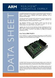
Introduction1.1 About the <strong>Cortex</strong>-<strong>A15</strong> <strong>MPCore</strong> processorThe <strong>Cortex</strong>-<strong>A15</strong> <strong>MPCore</strong> processor is a high-performance, low-power multiprocessor thatimplements the <strong>ARM</strong>v7-A architecture. The <strong>Cortex</strong>-<strong>A15</strong> <strong>MPCore</strong> processor has one to four<strong>Cortex</strong>-<strong>A15</strong> processors in a single multiprocessor device, or <strong>MPCore</strong> device, with L1 and L2cache subsystems.Figure 1-1 shows an example block diagram of a <strong>Cortex</strong>-<strong>A15</strong> <strong>MPCore</strong> processor configurationwith four processors.See Components of the processor on page 2-2 for a description of the <strong>Cortex</strong>-<strong>A15</strong> <strong>MPCore</strong>processor functional components.<strong>Cortex</strong>-<strong>A15</strong> <strong>MPCore</strong> processorAPB ATB Interrupts TimerEventsDebug andCTITraceGIC(optional)GenericTimerMiscellaneous<strong>Processor</strong> 0<strong>Processor</strong> 1<strong>Processor</strong> 2<strong>Processor</strong> 3L1ICacheL1DCacheTLBsL1ICacheL1DCacheTLBsL1ICacheL1DCacheTLBsL1ICacheL1DCacheTLBsSlaveMasterSnoopControlUnitL2 cacheACP ACE Level 2 memory systemFigure 1-1 Example multiprocessor configuration<strong>ARM</strong> DDI 0438I Copyright © 2011-2013 <strong>ARM</strong>. All rights reserved. 1-2ID062913Non-Confidential
Introduction1.2 ComplianceThe <strong>Cortex</strong>-<strong>A15</strong> <strong>MPCore</strong> processor complies with, or implements, the specifications describedin:• <strong>ARM</strong> architecture.• Advanced Microcontroller Bus Architecture.• Debug architecture on page 1-4.• Generic Interrupt Controller architecture on page 1-4.• Generic Timer architecture on page 1-4.• Program Flow Trace architecture on page 1-4.This TRM complements architecture reference manuals, architecture specifications, protocolspecifications, and relevant external standards. It does not duplicate information from thesesources.1.2.1 <strong>ARM</strong> architectureThe <strong>Cortex</strong>-<strong>A15</strong> <strong>MPCore</strong> processor implements the <strong>ARM</strong>v7-A architecture with the followingarchitecture extensions:• Advanced Single Instruction Multiple Data version 2 (SIMDv2) architecture extensionfor integer and floating-point vector operations.NoteThe Advanced SIMD architecture extension, its associated implementations, andsupporting software, are commonly referred to as NEON technology.• Vector Floating-Point version 4 (VFPv4) architecture extension for floating-pointcomputation that is fully compliant with the IEEE 754 standard.• Security Extensions for implementation of enhanced security.• Virtualization Extensions for the development of virtualized systems that enables theswitching of guest operating systems.• Large Physical Address Extension (LPAE) for address translation of up to 40 bits physicaladdresses.• Multiprocessing Extensions for multiprocessing functionality.See the <strong>ARM</strong> ® Architecture <strong>Reference</strong> <strong>Manual</strong> <strong>ARM</strong>v7-A and <strong>ARM</strong>v7-R edition.1.2.2 Advanced Microcontroller Bus ArchitectureThe <strong>Cortex</strong>-<strong>A15</strong> <strong>MPCore</strong> processor complies with the:• AMBA 4 Advanced eXtensible Interface (AXI) and AXI Coherency Extensions (ACE)protocol. See the <strong>ARM</strong> ® AMBA ® AXI and ACE Protocol Specification AXI3 , AXI4 ,and AXI4-Lite , ACE and ACE-Lite .• AMBA 3 Advanced Peripheral Bus (APB) protocol. See the <strong>ARM</strong> ® AMBA ® APB ProtocolSpecification.• AMBA 3 Advanced Trace Bus (ATB) protocol. See the <strong>ARM</strong> ® AMBA ® 3 ATB ProtocolSpecification.<strong>ARM</strong> DDI 0438I Copyright © 2011-2013 <strong>ARM</strong>. All rights reserved. 1-3ID062913Non-Confidential
Introduction1.2.3 Debug architectureThe <strong>Cortex</strong>-<strong>A15</strong> <strong>MPCore</strong> processor implements version 7.1 of the <strong>ARM</strong> Debug architecturethat complies with the CoreSight architecture. For more information, see the:• <strong>ARM</strong> ® Architecture <strong>Reference</strong> <strong>Manual</strong> <strong>ARM</strong>v7-A and <strong>ARM</strong>v7-R edition.• <strong>ARM</strong> ® CoreSight Architecture Specification.1.2.4 Generic Interrupt Controller architectureThe <strong>Cortex</strong>-<strong>A15</strong> <strong>MPCore</strong> processor implements version 2.0 of the <strong>ARM</strong> Generic InterruptController (GICv2) architecture that includes support for the Virtualization Extensions. See the<strong>ARM</strong> ® Generic Interrupt Controller Architecture Specification.1.2.5 Generic Timer architectureThe <strong>Cortex</strong>-<strong>A15</strong> <strong>MPCore</strong> processor implements the <strong>ARM</strong> Generic Timer architecture thatincludes support for the Virtualization Extensions. See the <strong>ARM</strong> ® Architecture <strong>Reference</strong><strong>Manual</strong> <strong>ARM</strong>v7-A and <strong>ARM</strong>v7-R edition.1.2.6 Program Flow Trace architectureThe <strong>Cortex</strong>-<strong>A15</strong> <strong>MPCore</strong> processor implements the Program Trace Macrocell (PTM) based onversion 1.1 of the Program Flow Trace (PFTv1.1) architecture. See the <strong>ARM</strong> ® CoreSight Program Flow Trace Architecture Specification.<strong>ARM</strong> DDI 0438I Copyright © 2011-2013 <strong>ARM</strong>. All rights reserved. 1-4ID062913Non-Confidential
Introduction1.3 FeaturesThe <strong>Cortex</strong>-<strong>A15</strong> <strong>MPCore</strong> processor includes the following features:• Full implementation of the <strong>ARM</strong>v7-A architecture instruction set with the architectureextensions listed in Compliance on page 1-3.• Superscalar, variable-length, out-of-order pipeline.• Dynamic branch prediction with Branch Target Buffer (BTB) and Global History Buffer(GHB), a return stack, and an indirect predictor.• Three separate 32-entry fully-associative Level 1 (L1) Translation Look-aside Buffers(TLBs), one for instruction, one for data loads, and one for data stores.• 4-way set-associative 512-entry Level 2 (L2) TLB in each processor.• Fixed 32KB L1 instruction and data caches.• Shared L2 cache of 512KB, 1MB, 2MB, or 4MB configurable size.• Optional Error Correction Code (ECC) protection for L1 data cache and L2 cache, andparity protection for L1 instruction cache.• AMBA 4 AXI Coherency Extensions (ACE) master interface.• Accelerator Coherency Port (ACP) that is implemented as an AXI3 slave interface.• Program Trace Macrocell (PTM) based on version 1.1 of the Program Flow Trace(PFTv1.1) architecture.• Performance Monitor Unit (PMU) based on PMUv2 architecture.• Cross trigger interfaces for multi-processor debugging.• VFP component only or optionally implemented VFP and NEON components.• Optional Generic Interrupt Controller (GIC) that supports up to 224 Shared PeripheralInterrupts (SPIs).• <strong>ARM</strong> generic 64-bit timers for each processor.• Support for power management with multiple power domains.1.3.1 Test featuresThe <strong>Cortex</strong>-<strong>A15</strong> <strong>MPCore</strong> processor provides several test signals that enable the use of bothATPG and MBIST to test the <strong>Cortex</strong>-<strong>A15</strong> <strong>MPCore</strong> processor and its memory arrays. SeeAppendix A Signal Descriptions for more information.<strong>ARM</strong> DDI 0438I Copyright © 2011-2013 <strong>ARM</strong>. All rights reserved. 1-5ID062913Non-Confidential
Introduction1.4 InterfacesThe processor has the following external interfaces:• Memory interface that implements an ACE master inferface.• ACP that implements as an AXI slave interface.• Debug interface that implements an APB slave interface.• Trace interface that implements an ATB interface.• Cross trigger interface.• DFT interface.• MBIST controller interface.See Interfaces on page 2-6 for more information on each of these interfaces.<strong>ARM</strong> DDI 0438I Copyright © 2011-2013 <strong>ARM</strong>. All rights reserved. 1-6ID062913Non-Confidential
Introduction1.5 Implementation optionsTable 1-1 lists the implementation options for the <strong>Cortex</strong>-<strong>A15</strong> <strong>MPCore</strong> processor.Table 1-1 <strong>Cortex</strong>-<strong>A15</strong> <strong>MPCore</strong> processor implementation optionsFeatureNumber of processorsL2 cache sizeRange of optionsUp to four processorsL2 cache size of:• 512KB.• 1MB.• 2MB.• 4MB.L2 tag RAM register slice 0 or 1L2 data RAM register slice 0, 1 or 2L2 arbitration register sliceL2 logic idle gated clockRegional gated clocks aECC/parity supportNEONVFPGeneric Interrupt ControllerIncluded or NotIncluded or NotIncluded or NotSupported in L1 and L2, L2 only, or noneIncluded or NotIncluded or NotIncluded or NotShared Peripheral Interrupts 0 to 224, in steps of 32<strong>Processor</strong> clock stop pins aPower switch and clamp pinsL1 data TLB page table sizeIncluded or NotIncluded or NotL1 data TLB page table size of:• 4KB entries only.• 4KB or 1MB entries.a. This feature is not available in revisions prior to r3p0.Note• All the processors share an integrated L2 cache and GIC. Each processor has the sameconfiguration for NEON, VFP, and L1 ECC or parity.• If you configure the design for one processor, it retains the system level coherency supportand the ACP slave port.• If you configure the design to exclude VFP, NEON is not available. You cannot configurethe design to exclude VFP but include NEON.• If you configure the design to exclude the GIC, SPIs and the remaining GIC signals arenot available, except PERIPHBASE[39:15].<strong>ARM</strong> DDI 0438I Copyright © 2011-2013 <strong>ARM</strong>. All rights reserved. 1-7ID062913Non-Confidential
Introduction• The L2 tag RAM register slice option adds register slices to the L2 tag RAMs. The L2data RAM register slice option adds register slices to the L2 data RAMs. Table 1-2 onpage 1-8 lists valid combinations of the L2 tag RAM and L2 data RAM register sliceoptions.• If L2 arbitration register slice is included, an additional pipeline stage for the CPU-L2arbitration logic interface is added to the L2 arbitration logic.• If L2 logic idle clock gating is present, most of the L2 logic is dynamically clock gatedwith a different clock than the GIC and Generic Timer. If L2 logic idle clock gating is notpresent, the L2 logic is not dynamically clock gated, and shares the same clock as the GICand Generic Timer. The clock gate generator for the L2 logic is also removed. Havingdynamic clock gating of the L2 logic can provide lower power dissipation, but at the costof a more complex clock tree implementation.• If regional clock gating is present, an additional level of clock gating occurs for severallogic blocks such as the register banks. Having regional clock gating can potentiallyprovide lower power dissipation, but at the cost of a more complex clock treeimplementation.Table 1-2 shows valid combinations of the L2 tag RAM and L2 data RAM register slice options.Table 1-2 Valid combinations of L2 tag and data RAM register sliceL2 tag RAMregister sliceL2 data RAMregister slice0 00 10 21 11 2<strong>ARM</strong> DDI 0438I Copyright © 2011-2013 <strong>ARM</strong>. All rights reserved. 1-8ID062913Non-Confidential
Introduction1.6 Product documentation and design flowThis section describes the <strong>Cortex</strong>-<strong>A15</strong> <strong>MPCore</strong> processor books and how they relate to thedesign flow in:• Documentation.• Design flow on page 1-10.See Additional reading on page ix for more information about the books described in thissection. For information on the relevant architectural standards and protocols, see Complianceon page 1-3.1.6.1 DocumentationThe <strong>Cortex</strong>-<strong>A15</strong> <strong>MPCore</strong> processor documentation is as follows:<strong>Technical</strong> <strong>Reference</strong> <strong>Manual</strong>The <strong>Technical</strong> <strong>Reference</strong> <strong>Manual</strong> (TRM) describes the functionality and theeffects of functional options on the behavior of the <strong>Cortex</strong>-<strong>A15</strong> <strong>MPCore</strong>processor. It is required at all stages of the design flow. The choices made in thedesign flow can mean that some behavior described in the TRM is not relevant.If you are programming the <strong>Cortex</strong>-<strong>A15</strong> <strong>MPCore</strong> processor, additionalinformation must be obtained from:• the implementer to determine the build configuration of the implementation• the integrator to determine the pin configuration of the device that you areusing.Note• The out-of-order design of the <strong>Cortex</strong>-<strong>A15</strong> <strong>MPCore</strong> processor pipelinemakes it impossible to provide accurate timing information for complexinstructions. The timing of an instruction can be affected by factors such as:— Other concurrent instructions.— Memory system activity.— Events outside the instruction flow.• Timing information has been provided in the past for some <strong>ARM</strong>processors to assist in detailed hand tuning of performance critical codesequences or in the development of an instruction scheduler within acompiler. This timing information is not required for producing optimizedinstruction sequences on the <strong>Cortex</strong>-<strong>A15</strong> <strong>MPCore</strong> processor. Theout-of-order pipeline of the <strong>Cortex</strong>-<strong>A15</strong> <strong>MPCore</strong> processor can scheduleand execute the instructions in an optimal fashion without any instructionreordering required.Configuration and Sign-off GuideThe <strong>ARM</strong> Configuration and Sign-off Guide (CSG) describes:• The available build configuration options and related issues in selectingthem.• How to configure the Register Transfer Level (RTL) source files with thebuild configuration options.• How to integrate RAM arrays.• How to run test vectors.• The processes to sign off the configured design.<strong>ARM</strong> DDI 0438I Copyright © 2011-2013 <strong>ARM</strong>. All rights reserved. 1-9ID062913Non-Confidential
IntroductionThe <strong>ARM</strong> product deliverables include reference scripts and information aboutusing them to implement your design. <strong>Reference</strong> methodology flows supplied by<strong>ARM</strong> are example reference implementations. For EDA tool support, contactyour EDA vendor.The CSG is a confidential book that is only available to licensees.1.6.2 Design flowThe <strong>Cortex</strong>-<strong>A15</strong> <strong>MPCore</strong> processor is delivered as synthesizable RTL. Before the processor canbe used in a product, it must go through the following process:ImplementationThe implementer configures and synthesizes the RTL to produce a hardmacrocell. This might include integrating the cache RAMs into the design.Integration The integrator connects the configured design into a SoC. This includesconnecting it to a memory system and peripherals.ProgrammingThis is the last process. The system programmer develops the SoC:• Software required to configure the <strong>Cortex</strong>-<strong>A15</strong> <strong>MPCore</strong> processor.• Software required to initialize the <strong>Cortex</strong>-<strong>A15</strong> <strong>MPCore</strong> processor.• Application software and the SoC tests.Each process:• Can be performed by a different party.• Can include implementation and integration choices that affect the behavior and featuresof the <strong>Cortex</strong>-<strong>A15</strong> <strong>MPCore</strong> processor.The operation of the final device depends on:Build configurationThe implementer chooses the options that affect how the RTL source files arepre-processed. These options usually include or exclude logic that can affect oneor more of the area, maximum frequency, and features of the resulting macrocell.Configuration inputsThe integrator configures some features of the <strong>Cortex</strong>-<strong>A15</strong> <strong>MPCore</strong> processor bytying inputs to specific values. These configurations affect the start-up behaviorbefore any software configuration is made. They can also limit the optionsavailable to the software.Software configurationThe programmer configures the <strong>Cortex</strong>-<strong>A15</strong> <strong>MPCore</strong> processor by programmingparticular values into registers. This affects the behavior of the <strong>Cortex</strong>-<strong>A15</strong><strong>MPCore</strong> processor.NoteThis manual refers to implementation-defined features that apply to build configuration options.<strong>Reference</strong> to a feature that is included means that the appropriate build and pin configurationoptions have been selected. <strong>Reference</strong> to an enabled feature means that the feature has also beenconfigured by software.<strong>ARM</strong> DDI 0438I Copyright © 2011-2013 <strong>ARM</strong>. All rights reserved. 1-10ID062913Non-Confidential
Introduction1.7 Product revisionsThis section describes the differences in functionality between product revisions.1.7.1 r0p0 - r0p1The following change has been made in this release:• ID register value changed to reflect product revision status:Main ID Register 0x410FC0F1Debug ID Register 0x3515F001• Various engineering errata fixes.1.7.2 r0p1 - r0p2The following change has been made in this release:• ID register value changed to reflect product revision status:Main ID Register 0x410FC0F2Debug ID Register 0x3515F002• Various engineering errata fixes.1.7.3 r0p2 - r0p3The following change has been made in this release:• ID register value changed to reflect product revision status:Main ID Register 0x410FC0F3Debug ID Register 0x3515F003• Various engineering errata fixes.1.7.4 r0p3 - r1p0The following changes have been made in this release:• ID register values changed to reflect product revision status:Main ID Register 0x411FC0F0Debug ID Register 0x3515F010ETM ID Register 0x411CF311Peripheral ID2 Register0x0000001B• Various engineering errata fixes.<strong>ARM</strong> DDI 0438I Copyright © 2011-2013 <strong>ARM</strong>. All rights reserved. 1-11ID062913Non-Confidential
Introduction1.7.5 r1p0 - r2p0The following changes have been made in this release:• ID register values changed to reflect product revision status:Main ID Register 0x412FC0F0Debug ID Register 0x3515F020ETM ID Register 0x411CF312Peripheral ID2 Register0x0000002B• The input signals, nVIRQ and nVFIQ, are always present regardless of whether the GICis present or not. See GIC configuration on page 8-6.• L2ACTLR bit[5] is now reserved, RAZ/WI. See L2 Auxiliary Control Register onpage 4-100.• Renamed PMCCFILTR to PMXEVTYPER31 in the PMU register summary table. SeeTable 11-1 on page 11-4.• Various engineering errata fixes.1.7.6 r2p0 - r2p1The following changes have been made in this release:• ID register values changed to reflect product revision status:Main ID Register 0x412FC0F1Debug ID Register 0x3515F021• Various engineering errata fixes.1.7.7 r2p1 - r2p2The following changes have been made in this release:• ID register values changed to reflect product revision status:Main ID Register 0x412FC0F2Debug ID Register 0x3515F022• Various engineering errata fixes.1.7.8 r2p2 - r3p0The following changes have been made in this release:• ID register values changed to reflect product revision status:Main ID Register 0x413FC0F0Debug ID Register 0x3515F030ETM ID Register 0x411CF313Peripheral ID2 Register0x0000003B• Added processor clock stop pins, CPUCLKOFF, configurable option. SeeImplementation options on page 1-7 and Clocks on page 2-8.<strong>ARM</strong> DDI 0438I Copyright © 2011-2013 <strong>ARM</strong>. All rights reserved. 1-12ID062913Non-Confidential
Introduction• Added regional clock gating configurable option. See Implementation options onpage 1-7 and Dynamic power management on page 2-21.• Added processor retention in WFI and WFE low-power state. See <strong>Processor</strong> retention inWFI and WFE low-power state on page 2-24.• Added L2ACTLR bits[26, 16:11]. See L2 Auxiliary Control Register on page 4-100.• Added ACTLR2 Register. See Auxiliary Control Register 2 on page 4-105.• Various engineering errata fixes.1.7.9 r3p0 - r3p1The following changes have been made in this release:• ID register values changed to reflect product revision status:Main ID Register 0x413FC0F1Debug ID Register 0x3515F031• Various engineering errata fixes.1.7.10 r3p1 - r3p2The following changes have been made in this release:• ID register values changed to reflect product revision status:Main ID Register 0x413FC0F2Debug ID Register 0x3515F032• Various engineering errata fixes.1.7.11 r3p2 - r3p3The following changes have been made in this release:• ID register values changed to reflect product revision status:Main ID Register 0x413FC0F3Debug ID Register 0x3515F033• Various engineering errata fixes.1.7.12 r3p3 - r4p0The following changes have been made in this release:• ID register values changed to reflect product revision status:Main ID Register 0x414FC0F0Debug ID Register 0x3515F040ETM ID Register 0x411CF314Peripheral ID2 Register0x0000004B• Added L2ACTLR bit[25]. See L2 Auxiliary Control Register on page 4-100.<strong>ARM</strong> DDI 0438I Copyright © 2011-2013 <strong>ARM</strong>. All rights reserved. 1-13ID062913Non-Confidential
Introduction• Added L1 data TLB support for 1MB page table entries. See Implementation options onpage 1-7 and L1 data TLB on page 5-3.• Various engineering errata fixes.<strong>ARM</strong> DDI 0438I Copyright © 2011-2013 <strong>ARM</strong>. All rights reserved. 1-14ID062913Non-Confidential
Chapter 2Functional DescriptionThis chapter describes the functionality of the <strong>Cortex</strong>-<strong>A15</strong> <strong>MPCore</strong> processor. It contains thefollowing sections:• About the <strong>Cortex</strong>-<strong>A15</strong> <strong>MPCore</strong> processor functions on page 2-2.• Interfaces on page 2-6.• Clocking and resets on page 2-8.• Power management on page 2-21.<strong>ARM</strong> DDI 0438I Copyright © 2011-2013 <strong>ARM</strong>. All rights reserved. 2-1ID062913Non-Confidential
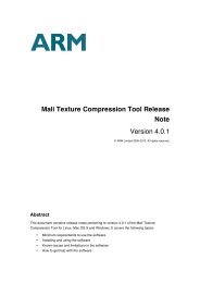
Functional Description2.1 About the <strong>Cortex</strong>-<strong>A15</strong> <strong>MPCore</strong> processor functionsFigure 2-1 shows a top-level functional diagram of the <strong>Cortex</strong>-<strong>A15</strong> <strong>MPCore</strong> processor.<strong>Cortex</strong>-<strong>A15</strong> <strong>MPCore</strong> processorAPB ATB Interrupts TimerEventsDebug andCTITraceGIC(optional)GenericTimerMiscellaneousDebugPTMPMULoopBufferDecodeRenameVirtual toPhysicalRegisterPoolDispatch stagesIntegerExecuteNEONVFPWritebackBranchpredictionInd PredReturnStackInstructionFetchInstructionCacheITLBCP14CP15RegisterFileL2-TLBLOADSTORELTLBSTLBDataCache1 st level arbitration<strong>Processor</strong> 0<strong>Processor</strong> 1 †<strong>Processor</strong> 2 †<strong>Processor</strong> 3 †2 nd level arbitrationSlaveMasterFill / EvictBuffersL2 Cache(512KB to 4 MB)SnoopControl UnitAuto PrefetchEngineACPACELevel 2 memory system† OptionalFigure 2-1 Block diagram2.1.1 Components of the processorThe main components of the processor are:• Instruction fetch on page 2-3.• Instruction decode on page 2-3.• Instruction dispatch on page 2-3.• Integer execute on page 2-3.• Load/Store unit on page 2-4.• L2 memory system on page 2-4.<strong>ARM</strong> DDI 0438I Copyright © 2011-2013 <strong>ARM</strong>. All rights reserved. 2-2ID062913Non-Confidential
Functional Description• NEON and VFP unit on page 2-4.• Generic Interrupt Controller on page 2-4.• Generic Timer on page 2-4.• Debug and trace on page 2-4.Instruction fetchThe instruction fetch unit fetches instructions from the L1 instruction cache and delivers up tothree instructions per cycle to the instruction decode unit. It supports dynamic and static branchprediction. The instruction fetch unit includes:• L1 instruction cache that is a 32KB 2-way set-associative cache with 64 bytes cache lineand optional parity protection per 16-bits.• 2-level dynamic predictor with BTB for fast target generation.• Return stack.• Static branch predictor.• Indirect predictor.• 32-entry fully-associative L1 instruction TLB.Instruction decodeThe instruction decode unit decodes the following instructions:• <strong>ARM</strong>.• Thumb.• ThumbEE.• Advanced SIMD.• CP14.• CP15.The instruction decode unit also performs register renaming to facilitate out-of-order executionby removing Write-After-Write (WAW) and Write-After-Read (WAR) hazards. A loop bufferprovides additional power savings while executing small instruction loops.Instruction dispatchThe instruction dispatch unit controls when the decoded instructions can be dispatched to theexecution pipelines and when the returned results can be retired. It includes:• The <strong>ARM</strong> core general purpose registers.• The Advanced SIMD and VFP extension register set.• The CP14 and CP15 registers.• The APSR and FPSCR flag bits.Integer executeThe integer execute unit includes:• Two symmetric Arithmetic Logical Unit (ALU) pipelines.• Integer multiply-accumulate pipeline.• Iterative integer divide hardware.• Branch and instruction condition codes resolution logic.• Result forwarding and comparator logic.<strong>ARM</strong> DDI 0438I Copyright © 2011-2013 <strong>ARM</strong>. All rights reserved. 2-3ID062913Non-Confidential
Functional DescriptionLoad/Store unitThe load/store unit executes load and store instructions and encompasses the L1 data sidememory system. It also services memory coherency requests from the L2 memory system. Theload/store unit includes:• L1 data cache that is a 32KB 2-way set-associative cache with 64 bytes cache line andoptional ECC protection per 32-bits.• Two separate 32-entry fully-associative L1 TLBs, one for data loads and one for datastores.See Chapter 5 Memory Management Unit and Chapter 6 Level 1 Memory System for moreinformation.L2 memory systemThe L2 memory system services L1 instruction and data cache misses from each processor. Ithandles requests on the AMBA 4 ACE master interface and AXI3 ACP slave interface. The L2memory system includes:• L2 cache that is:— 512KB, 1MB, 2MB, or 4MB configurable size.— 16-way set-associative cache with optional ECC protection per 64-bits.• Duplicate copy of L1 data cache tag RAMs from each processor for handling snooprequests.• 4-way set-associative of 512-entry L2 TLB in each processor.• Automatic hardware prefetcher with programmable instruction fetch and load/store dataprefetch distances.See Chapter 7 Level 2 Memory System for more information.NEON and VFP unitThe NEON and VFP unit provides support for the <strong>ARM</strong>v7 Advanced SIMDv2 and VFPv4instruction sets. See Chapter 14 NEON and VFP Unit for more information.Generic Interrupt ControllerThe GIC provides support for handling multiple interrupt sources. See Chapter 8 GenericInterrupt Controller for more information.Generic TimerThe Generic Timer provides the ability to schedule events and trigger interrupts. See Chapter 9Generic Timer for more information.Debug and traceThe debug and trace unit includes:• Support for <strong>ARM</strong>v7.1 Debug architecture with an APB slave interface for access to thedebug registers.• Performance Monitor Unit based on PMUv2 architecture.<strong>ARM</strong> DDI 0438I Copyright © 2011-2013 <strong>ARM</strong>. All rights reserved. 2-4ID062913Non-Confidential
Functional Description• Program Trace Macrocell based on the CoreSight PFTv1.1 architecture and dedicatedATB interface per processor.• Cross trigger interfaces for multi-processor debugging.See the following for more information:• Chapter 10 Debug.• Chapter 11 Performance Monitor Unit.• Chapter 12 Program Trace Macrocell.• Chapter 13 Cross Trigger on page 13-1.<strong>ARM</strong> DDI 0438I Copyright © 2011-2013 <strong>ARM</strong>. All rights reserved. 2-5ID062913Non-Confidential
Functional Description2.2 InterfacesThe processor has the following external interfaces:• ACE master interface.• ACP slave interface.• APB slave interface.• ATB interface.• Cross trigger interface.• DFT interface on page 2-7.• MBIST controller interface on page 2-7.2.2.1 ACE master interfaceThe processor implements an AMBA 4 AXI Coherency Extensions (ACE) master interface. Seethe <strong>ARM</strong> ® AMBA ® AXI and ACE Protocol Specification AXI3 , AXI4 , and AXI4-Lite , ACEand ACE-Lite for more information.ACE is an extension to the AXI protocol and provides the following enhancements:• Support for hardware coherent caches.• Barrier transactions that guarantee transaction ordering.• Distributed virtual memory messaging, enabling management of a virtual memorysystem.2.2.2 ACP slave interfaceThe processor implements an AMBA 3 AXI Accelerator Coherency Port (ACP) slave interface.See the <strong>ARM</strong> ® AMBA ® AXI and ACE Protocol Specification AXI3 , AXI4 , and AXI4-Lite ,ACE and ACE-Lite for more information.ACP is an implementation of an AMBA 3 AXI slave interface. It supports memory coherentaccesses to the processor memory system, but cannot receive coherent requests, barriers ordistributed virtual memory messages.2.2.3 APB slave interfaceThe processor implements an AMBA 3 APB slave interface that enables access to the debugregisters. See the <strong>ARM</strong> CoreSight Architecture Specification for more information.2.2.4 ATB interfaceThe processor implements dedicated AMBA 3 ATB interfaces for each processor that outputstrace information for debugging. The ATB interface is compatible with the CoreSightarchitecture. See the <strong>ARM</strong> ® CoreSight Architecture Specification for more information.2.2.5 Cross trigger interfaceThe processor implements a single cross trigger channel interface. This external interface isconnected to the CoreSight Cross Trigger Interface (CTI) corresponding to each processorthrough a simplified Cross Trigger Matrix (CTM). See Chapter 13 Cross Trigger for moreinformation.<strong>ARM</strong> DDI 0438I Copyright © 2011-2013 <strong>ARM</strong>. All rights reserved. 2-6ID062913Non-Confidential
Functional Description2.2.6 DFT interfaceThe processor implements a Design For Test (DFT) interface that enables an industry standardAutomatic Test Pattern Generation (ATPG) tool to test logic outside of the embedded memories.See DFT and MBIST interfaces on page A-26 for information on these test signals.2.2.7 MBIST controller interfaceThe Memory Built In Self Test (MBIST) controller interface provides support for manufacturingtesting of the memories embedded in the <strong>Cortex</strong>-<strong>A15</strong> <strong>MPCore</strong> processor. MBIST is the industrystandard method of testing embedded memories. MBIST works by performing sequences ofreads and writes to the memory based on test algorithms. See MBIST interface on page A-26 forinformation on the MBIST signals.<strong>ARM</strong> DDI 0438I Copyright © 2011-2013 <strong>ARM</strong>. All rights reserved. 2-7ID062913Non-Confidential
Functional Description2.3 Clocking and resetsThis section describes the clocks and resets of the processor in:• Clocks.• Resets on page 2-11.2.3.1 ClocksThe processor has the following clock inputs:CLKThis is the main clock of the <strong>Cortex</strong>-<strong>A15</strong> <strong>MPCore</strong> processor. All processors, theshared L2 memory system logic, the GIC, and the Generic Timer are clocked witha distributed version of CLK.PCLKDBG This is the APB clock that controls the Debug APB, CTI and CTM logic in thePCLKDBG domain. PCLKDBG is asynchronous to CLK.The processor has the following clock enable inputs:ACLKENM The AXI master interface is a synchronous AXI interface that can operate at anyinteger multiple that is equal to or slower than the main processor clock, CLK,using the ACLKENM signal. For example, you can set the CLK to ACLKMfrequency ratio to 1:1, 2:1, or 3:1, where ACLKM is the AXI master clock.ACLKENM asserts one CLK cycle prior to the rising edge of ACLKM.Software can change the CLK to ACLKM frequency ratio dynamically usingACLKENM.Figure 2-2 shows a timing example of ACLKENM that changes the CLK toACLKM frequency ratio from 3:1 to 1:1.1 CLKcycle1 CLKcycleCLKACLKENMACLKENM asserts one CLK cyclebefore the rising edge of ACLKMACLKMCLK:ACLKM = 3:1 CLK:ACLKM = 1:1Figure 2-2 ACLKENM with CLK:ACLKM ratio changing from 3:1 to 1:1NoteFigure 2-2 shows the timing relationship between the AXI master clock,ACLKM and ACLKENM, where ACLKENM asserts one CLK cycle beforethe rising edge of ACLKM. It is important that the relationship betweenACLKM and ACLKENM is maintained.ACLKENS ACP is a synchronous AXI slave interface that can operate at any integer multiplethat is equal to or slower than the main processor clock, CLK, using theACLKENS signal. For example, the CLK to ACLKS frequency ratio can be 1:1,2:1, or 3:1, where ACLKS is the AXI slave clock. ACLKENS asserts one CLKcycle before the rising edge of ACLKS. The CLK to ACLKS frequency ratio canbe changed dynamically using ACLKENS.<strong>ARM</strong> DDI 0438I Copyright © 2011-2013 <strong>ARM</strong>. All rights reserved. 2-8ID062913Non-Confidential
Functional DescriptionFigure 2-3 shows a timing example of ACLKENS that changes the CLK toACLKS frequency ratio from 3:1 to 1:1.1 CLKcycle1 CLKcycleCLKACLKENSACLKENS asserts one CLK cyclebefore the rising edge of ACLKSACLKSCLK:ACLKS = 3:1 CLK:ACLKS = 1:1Figure 2-3 ACLKENS with CLK:ACLKS ratio changing from 3:1 to 1:1NoteFigure 2-3 shows the timing relationship between the ACP clock, ACLKS andACLKENS, where ACLKENS asserts one CLK cycle before the rising edge ofACLKS. It is important that the relationship between ACLKS and ACLKENSis maintained.PCLKENDBGThe Debug APB interface is an asynchronous interface that can operate at anyinteger multiple that is equal to or slower than the APB clock, PCLKDBG, usingthe PCLKENDBG signal. For example, the PCLKDBG to internal PCLKDBGfrequency ratio can be 1:1, 2:1, or 3:1. PCLKENDBG asserts one PCLKDBGcycle before the rising edge of the internal PCLKDBG. The PCLKDBG tointernal PCLKDBG frequency ratio can be changed dynamically usingPCLKENDBG.Figure 2-4 shows a timing example of PCLKENDBG that changes thePCLKDBG to internal PCLKDBG frequency ratio from 2:1 to 1:1.1 PCLKDBGcycle1 PCLKDBGcyclePCLKDBGPCLKENDBGinternalPCLKDBGPCLKENDBG asserts one PCLKDBG cyclebefore the rising edge of internal PCLKDBGPCLKDBG:internal PCLKDBG = 2:1 PCLKDBG:internal PCLKDBG = 1:1Figure 2-4 PCLKENDBG with PCLKDBG:internal PCLKDBG ratio changing from 2:1 to 1:1ATCLKEN The ATB interface is a synchronous interface that can operate at any integermultiple that is slower than the main processor clock, CLK, using theATCLKEN signal. For example, the CLK to ATCLK frequency ratio can be 2:1,3:1, or 4:1, where ATCLK is the ATB bus clock. ATCLKEN asserts three CLKcycles before the rising edge of ATCLK. Three CLK cycles are required topermit propagation delay from the ATCLKEN input to the processor. The CLKto ATCLK frequency ratio can be changed dynamically using ATCLKEN.<strong>ARM</strong> DDI 0438I Copyright © 2011-2013 <strong>ARM</strong>. All rights reserved. 2-9ID062913Non-Confidential
Functional DescriptionFigure 2-5 shows a timing example of ATCLKEN where the CLK to ATCLKfrequency ratio is 2:1.3 CLK cyclesCLKATCLKENATCLKEN asserts three CLK cyclesbefore the rising edge of ATCLKATCLKFigure 2-5 ATCLKEN with CLK:ATCLK ratio at 2:1PERIPHCLKENThis is the synchronous clock enable signal for the GIC. The GIC can operate atany integer multiple that is slower than the main processor clock, CLK, using thePERIPHCLKEN signal. For example, the CLK to internal GIC clock frequencyratio can be 2:1 or 3:1. The GIC does not support a 1:1 clock frequency ratio.PERIPHCLKEN asserts one CLK cycle prior to the rising edge of the internalIC clock. The CLK to internal IC clock frequency ratio can be changeddynamically using PERIPHCLKEN.CLKNoteIf you configure your design to exclude the GIC, this signal does not exist.Figure 2-6 shows a timing example of PERIPHCLKEN where the CLK tointernal GIC frequency ratio is 2:1.1 CLKcycleCLK:ATCLK = 2:1PERIPHCLKENinternal GIC clockPERIPHCLKEN asserts one CLK cyclebefore the rising edge of internal GIC clockCLK:internal GIC clock = 2:1Figure 2-6 PERIPHCLKEN with CLK:internal IC clock ratio at 2:1CLKENThis is the main clock enable for all internal clocks in the <strong>Cortex</strong>-<strong>A15</strong> <strong>MPCore</strong>processor that are derived from CLK. There is one CLK cycle delay between theassertion of CLKEN and the internal clocks that are enabled. When all theprocessors and L2 are in WFI low-power state, you can place the processor in alow-power state using the CLKEN input. This disables all internal clocks,excluding the asynchronous Debug APB PCLKDBG domain. See L2 Wait forInterrupt on page 2-23.CPUCLKOFFNoteThis configuration option is not available in revisions prior to r3p0.<strong>ARM</strong> DDI 0438I Copyright © 2011-2013 <strong>ARM</strong>. All rights reserved. 2-10ID062913Non-Confidential
Functional DescriptionThese pins are only present if you configure the <strong>Cortex</strong>-<strong>A15</strong> <strong>MPCore</strong> processorto include them. If you configure the processor to include the CPUCLKOFFpins, there is one CPUCLKOFF input pin and a new top-level clock gateinstantiated for each processor. When CPUCLKOFF is asserted, the processorclock is stopped. This pin must be tied LOW or 1'b0 in normal functionaloperation, and can only be asserted under strict conditions. Having externalcontrol of the processor clock enable permits the SoC to assert CPUCLKOFFwhen the processor is already powered down, or when the processor is poweredup. However, CPUCLKOFF must be deasserted after power has beencompletely restored, at least 16 cycles before the deassertion of the processorreset, and at least 16 cycles before releasing the clamps on the processor outputs,to permit the powerup reset sequence to complete.NoteBecause configuring the <strong>Cortex</strong>-<strong>A15</strong> <strong>MPCore</strong> processor with the CPUCLKOFFpins adds a new top-level clock gate for each processor, it might increase theclock skew between the processors.2.3.2 ResetsThe processor has the following reset inputs:nCPUPORESET[3:0]The nCPUPORESET signal initializes all the processor logic, includingthe NEON and VFP logic, Debug, PTM, breakpoint and watchpoint logicin the processor CLK domain. Each processor has one nCPUPORESETreset input.nCORERESET[3:0]The nCORERESET signal initializes the processor logic, including theNEON and VFP logic but excludes the Debug, PTM, breakpoint andwatchpoint logic. Each processor has one nCORERESET reset input.nCXRESET[3:0]The nCXRESET signal initializes the NEON and VFP logic. This resetcan be used to hold the NEON and VFP unit in a reset state so that thepower to the unit can be safely applied during power up. Each processorhas one nCXRESET reset input.nDBGRESET[3:0] The nDBGRESET signal initializes the Debug, PTM, breakpoint andwatchpoint logic in the processor CLK domain. Each processor has onenDBGRESET reset input.nPRESETDBGnL2RESETThe nPRESETDBG signal initializes the shared Debug APB, CTI, andCTM logic in the PCLKDBG domain.The nL2RESET signal initializes the shared L2 memory system, InterruptController, and Timer logic.<strong>ARM</strong> DDI 0438I Copyright © 2011-2013 <strong>ARM</strong>. All rights reserved. 2-11ID062913Non-Confidential
Functional DescriptionAll resets are active-LOW inputs. The reset signals lets you reset different parts of the processorindependently. Table 2-1 shows the areas of the processor controlled by the various resetsignals. In this table, [3:0] specifies the processor configuration.Table 2-1 Areas controlled by reset signalsReset signal<strong>Processor</strong> a(CLK)NEON andVFP (CLK)Debug andPTM b(CLK)Debug APB,CTI, and CTM(PCLKDBG)L2 memory system,GIC, and GenericTimer (CLK)nCPUPORESET[3:0] Reset Reset Reset - -nCORERESET[3:0] Reset Reset - - -nCXRESET[3:0] - Reset - - -nDBGRESET[3:0] - - Reset - -nPRESETDBG - - - Reset -nL2RESET - - - - Reseta. <strong>Processor</strong> logic, excluding NEON and VFP, Debug, PTM, breakpoint and watchpoint logic.b. Debug, PTM, breakpoint and watchpoint logic.Table 2-2 on page 2-13 shows the valid combinations for the reset signals to enable:• Powerup reset for all processors or an individual processor.• Software reset for all processors or an individual processor.• Logic held in reset for power up. See Power management on page 2-21 for the validpowerup and powerdown combinations.<strong>ARM</strong> DDI 0438I Copyright © 2011-2013 <strong>ARM</strong>. All rights reserved. 2-12ID062913Non-Confidential
Functional DescriptionReset combination Signals Value DescriptionTable 2-2 Valid reset combinations (continued)NEON and VFP and Debug(PCLKDBG) resetnCPUPORESET [3:0]nCORERESET [3:0]nCXRESET [3:0]nDBGRESET [3:0]nPRESETDBGnL2RESET[n] = 1[n] = 1[n] = 0[n] = 101NEON and VFP and Debug (PCLKDBG) are held inreset, so that NEON and VFP and Debug(PCLKDBG) can be powered up.NEON and VFP and Debug (CLK)resetnCPUPORESET [3:0]nCORERESET [3:0]nCXRESET [3:0]nDBGRESET [3:0]nPRESETDBGnL2RESET[n] = 1[n] = 1[n] = 0[n] = 011NEON and VFP and Debug (CLK) are held in reset.Run mode nCPUPORESET [3:0]nCORERESET [3:0]nCXRESET [3:0]nDBGRESET [3:0]nPRESETDBGnL2RESET111111No logic is held in reset.a. For powerup reset or processor reset, nCPUPORESET must be asserted. The remaining processor resets, nCORERESET, nCXRESET,and nDBGRESET can be asserted, but is not required.b. For soft reset, nCORERESET must be asserted, nCXRESET can be asserted, but is not required.Note• nL2RESET resets the shared L2 memory system logic, GIC and Generic Timer that iscommon to all processors. This reset must not be asserted while any individual processoris active.• nPRESETDBG resets the shared Debug in PCLKDBG domain that is common to allprocessors. This reset must not be asserted while any individual processor is activelybeing debugged in normal operating mode or during external debug over power down.• If your implementation does not include the NEON and VFP unit, you can tie thenCXRESET input HIGH.There are specific requirements that you must meet to reset each reset domain listed in Table 2-1on page 2-12. Not adhering to these requirements can lead to a reset domain that is notfunctional.The reset sequences in the following sections are the only reset sequences that <strong>ARM</strong>recommends. Any deviation from these sequences might cause an improper reset of that resetdomain.The supported reset sequences are:• Powerup reset on page 2-16.• Soft reset on page 2-17.• NEON and VFP reset on page 2-18.• Debug PCLKDBG reset on page 2-19.• Memory arrays reset on page 2-19.<strong>ARM</strong> DDI 0438I Copyright © 2011-2013 <strong>ARM</strong>. All rights reserved. 2-15ID062913Non-Confidential
Functional DescriptionPowerup resetThe full powerup reset initializes all logic in the <strong>Cortex</strong>-<strong>A15</strong> <strong>MPCore</strong> processor. You must applypowerup reset to the <strong>Cortex</strong>-<strong>A15</strong> <strong>MPCore</strong> processor when power is first applied to the SoC.Logic in all clock domains are placed in a benign state following the deassertion of the resetsequence.Figure 2-7 shows the full powerup reset sequence for the <strong>Cortex</strong>-<strong>A15</strong> <strong>MPCore</strong> processor.CLKnCPUPORESET[3:0]nCORERESET[3:0]optionalnCXRESET[3:0]optionalnDBGRESET[3:0]optionalnL2RESETnPRESETDBG16 CLK cycles minimum16 CLK cycles minimum16 CLK cycles minimum16 CLK cycles minimum16 CLK cycles minimum16 PCLKDBG cycles minimumFigure 2-7 Powerup reset timingOn full powerup reset for the <strong>Cortex</strong>-<strong>A15</strong> <strong>MPCore</strong> processor, perform the following resetsequence:1. Apply nCPUPORESET, nL2RESET, and nPRESETDBG. The remaining processorresets, nCORERESET, nCXRESET, and nDBGRESET can be asserted, but is notrequired.2. nCPUPORESET and nL2RESET must be asserted for at least 16 CLK cycles.nPRESETDBG must be asserted for at least16 PCLKDBG cycles. Holding the resets forthis duration ensures that the resets have propagated to all locations within the processor.3. nL2RESET must be deasserted in the same cycle as the processor resets, or before anyof the processor resets are deasserted.Individual processor powerup reset initializes all logic in a single processor. You must apply thepowerup reset when the individual processor is in powered state. In implementations where eachprocessor has its own power supply, the powerup reset holds the processor in a reset state so thatpower to the processor can be safely applied. You must apply the correct sequence beforeapplying a powerup reset to that processor.For individual processor powerup reset:• nCPUPORESET for that processor must be asserted for at least 16 CLK cycles.• nL2RESET must not be asserted while any individual processor is active.• nPRESETDBG must not be asserted while any individual processor is actively beingdebugged in normal operating mode or during external debug over power down.<strong>ARM</strong> DDI 0438I Copyright © 2011-2013 <strong>ARM</strong>. All rights reserved. 2-16ID062913Non-Confidential
Functional DescriptionSoft resetThe full soft reset initializes all logic in each of the individual processor apart from the Debugand PTM logic in the CLK domain. All breakpoints and watchpoints are retained during a softreset sequence. By asserting only nCORERESET, the reset domains controlled bynDBGRESET, nPRESETDBG, and nL2RESET, that is, the Debug and PTM in CLK, DebugAPB in PCLKDBG, and the shared L2 memory system, GIC, and Generic Timer domains, arenot reset.Figure 2-8 shows the full soft reset sequence for the <strong>Cortex</strong>-<strong>A15</strong> <strong>MPCore</strong> processor.CLKnCPUPORESET[3:0]nDBGRESET[3:0]nL2RESETnPRESETDBGHIGH-inactiveHIGH-inactiveHIGH-inactiveHIGH-inactivenCORERESET[3:0]16 CLK cycles minimumnCXRESET[3:0]optional16 CLK cycles minimumFigure 2-8 Soft reset timingOn full soft reset for the <strong>Cortex</strong>-<strong>A15</strong> <strong>MPCore</strong> processor, perform the following reset sequence:1. You must apply steps 1 to 8 in the processor powerdown sequence, see <strong>Processor</strong> powerdomain on page 2-30, and wait until STANDBYWFI is asserted, indicating that theprocessor is idle, before asserting nCORERESET for that processor.2. Apply nCORERESET, nCXRESET can be asserted, but is not required.3. After both resets have been asserted for 5 cycles, the clamps can be released.4. nCORERESET must be asserted for at least 16 CLK cycles.5. If nCXRESET is asserted, both resets must be deasserted in the same cycle.Individual processor soft reset initializes all logic in a single processor apart from its Debug,PTM, breakpoint and watchpoint logic. Breakpoints and watchpoints for that processor areretained. You must apply the correct sequence before applying soft reset to that processor.For individual processor soft reset:• You must apply steps 1 to 8 in the processor powerdown sequence, see <strong>Processor</strong> powerdomain on page 2-30, and wait until STANDBYWFI is asserted, indicating that theprocessor is idle, before asserting nCORERESET for that processor.NoteFor a single processor configuration you can omit step 3 that clears the ACTLR SMP bit.• nCORERESET for that processor must be asserted for at least 16 CLK cycles.• nL2RESET must not be asserted while any individual processor is active.<strong>ARM</strong> DDI 0438I Copyright © 2011-2013 <strong>ARM</strong>. All rights reserved. 2-17ID062913Non-Confidential
Functional Description• nPRESETDBG must not be asserted while any individual processor is actively beingdebugged in normal operating mode.NEON and VFP resetAn additional reset controls the NEON and VFP unit, independently of the processor reset. Youcan use this reset to hold the NEON and VFP unit in a reset state so that the power to this unitcan be safely applied during power up.The reset cycle timing requirements for nCXRESET are identical to those for nCORERESET.nCXRESET must be held for a minimum of 16 CLK cycles when asserted to guarantee thatthe NEON and VFP unit has entered a reset state.Figure 2-9 shows the NEON and VFP reset sequence.CLKnCPUPORESET[3:0]nCORERESET[3:0]nDBGRESET[3:0]nL2RESETnPRESETDBGHIGH-inactiveHIGH-inactiveHIGH-inactiveHIGH-inactiveHIGH-inactivenCXRESET[3:0]16 CLK cycles minimumFigure 2-9 NEON and VFP reset timingNoteIf your implementation does not include the NEON and VFP unit, you can tie the nCXRESETinputs HIGH.Debug CLK resetUse nDBGRESET to reset the processor, Debug, PTM, breakpoint and watchpoint logic in theCLK domain.To safely reset the Debug CLK unit, nDBGRESET must be asserted for a minimum of 16 CLKcycles.Figure 2-10 on page 2-19 shows the Debug CLK reset sequence.<strong>ARM</strong> DDI 0438I Copyright © 2011-2013 <strong>ARM</strong>. All rights reserved. 2-18ID062913Non-Confidential
Functional DescriptionCLKnCPUPORESET[3:0]nCORERESET[3:0]nCXRESET[3:0]nPRESETDBG[3:0]nL2RESETHIGH-inactiveHIGH-inactiveHIGH-inactiveHIGH-inactiveHIGH-inactivenDBGRESET16 CLK cycles minimumFigure 2-10 Debug CLK reset timingDebug PCLKDBG resetUse nPRESETDBG to reset the Debug APB, CTI and CTM logic in the PCLKDBG domain.This reset holds the Debug PCLKDBG unit in a reset state so that the power to the unit can besafely applied during power up.To safely reset the Debug PCLKDBG unit, nPRESETDBG must be asserted for a minimum of16 PCLKDBG cycles.Figure 2-11 shows the Debug PCLKDBG reset sequence.PCLKDBGnCPUPORESET[3:0]nCORERESET[3:0]nCXRESET[3:0]nDBGRESET[3:0]nL2RESETHIGH-inactiveHIGH-inactiveHIGH-inactiveHIGH-inactiveHIGH-inactivenPRESETDBG16 PCLKDBG cycles minimumFigure 2-11 Debug PCLKDBG reset timingMemory arrays resetDuring a processor reset, the following memory arrays in the processor are invalidated at reset:• Branch Prediction arrays such as BTB, GHB, and Indirect Predictor.• L1 instruction and data TLBs.• L1 instruction and data caches.<strong>ARM</strong> DDI 0438I Copyright © 2011-2013 <strong>ARM</strong>. All rights reserved. 2-19ID062913Non-Confidential
Functional Description• L2 unified TLB.In addition to these processor memory arrays, during a powerup reset, the following shareablememory arrays are invalidated at reset:• L2 duplicate snoop tag RAM.• L2 prefetch stride queue RAM.• L2 unified cache RAM, if L2RSTDISABLE is tied LOW.The L1 instruction and data cache resets can take up to 128 CLK cycles after the deassertingedge of the reset signals, with each array being reset in parallel. Depending on the size of the L2cache, the L2 cache reset can take 640 CLK cycles for a 512KB L2 cache and 5120 CLK cyclesfor a 4MB L2 cache. The L2 cache reset occurs in the background, in parallel with the L1 cacheresets. The processor can begin execution in non-cacheable state, but any attempt to performcacheable transactions stalls the processor until the appropriate cache reset is complete.The branch prediction arrays require 512 CLK cycles to reset after the deasserting edge of reset.The processor begins execution with branch prediction disabled, any attempt to enable branchprediction with the SCTLR.Z bit, stalls the processor until the branch prediction cache resets arecomplete.The <strong>Cortex</strong>-<strong>A15</strong> <strong>MPCore</strong> processor has an input signal, L2RSTDISABLE, that controls the L2cache hardware reset process. The usage models for the L2RSTDISABLE signal are asfollows:• When the <strong>Cortex</strong>-<strong>A15</strong> <strong>MPCore</strong> processor powers up for the first time, L2RSTDISABLEmust be held LOW to invalidate the L2 cache using the L2 cache hardware resetmechanism.• For systems that do not retain the L2 cache RAM contents while the L2 memory systemis powered down, L2RSTDISABLE must be held LOW to invalidate the L2 cache usingthe L2 cache hardware reset mechanism.• For systems that retain the L2 cache RAM contents while the L2 memory system ispowered down, L2RSTDISABLE must be held HIGH to disable the L2 cache hardwarereset mechanism.The L2RSTDISABLE signal is sampled during nL2RESET assertion and must be held aminimum of 32 CLK cycles after the deasserting edge of nL2RESET.<strong>ARM</strong> DDI 0438I Copyright © 2011-2013 <strong>ARM</strong>. All rights reserved. 2-20ID062913Non-Confidential
Functional Description2.4 Power managementThe <strong>Cortex</strong>-<strong>A15</strong> <strong>MPCore</strong> processor provides mechanisms and support to control both dynamicand static power dissipation. The following sections describe:• Dynamic power management.• Power domains on page 2-28.• Power modes on page 2-29.• Event communication using WFE and SEV instructions on page 2-37.2.4.1 Dynamic power managementThis section describes the following dynamic power management features in the <strong>Cortex</strong>-<strong>A15</strong><strong>MPCore</strong> processor:• <strong>Processor</strong> Wait for Interrupt.• <strong>Processor</strong> Wait for Event on page 2-22.• L2 Wait for Interrupt on page 2-23.• <strong>Processor</strong> retention in WFI and WFE low-power state on page 2-24.• NEON and VFP clock gating on page 2-27.• L2 control and tag banks clock gating on page 2-27.• Regional clock gating on page 2-28.<strong>Processor</strong> Wait for InterruptWait for Interrupt is a feature of the <strong>ARM</strong>v7-A architecture that puts the processor in a lowpower state by disabling most of the clocks in the processor while keeping the processorpowered up. This reduces the power drawn to the static leakage current, leaving a small clockpower overhead to enable the processor to wake up from WFI low-power state.A processor enters into WFI low-power state by executing the WFI instruction.When executing the WFI instruction, the processor waits for all instructions in the processor toretire before entering the idle or low power state. The WFI instruction ensures that all explicitmemory accesses occurred before the WFI instruction in program order, have retired. Forexample, the WFI instruction ensures that the following instructions received the required data orresponses from the L2 memory system:• Load instructions.• Cache and TLB maintenance operations.• Store exclusives instructions.In addition, the WFI instruction ensures that store instructions have updated the cache or havebeen issued to the L2 memory system.While the processor is in WFI low-power state, the clocks in the processor are temporarilyenabled without causing the processor to exit WFI low-power state, when any of the followingevents are detected:• An L2 snoop request that must be serviced by the processor L1 data cache.• A cache, TLB or BTB maintenance operation that must be serviced by the processor L1instruction cache, data cache, instruction TLB, data TLB, or BTB.• An APB access to the debug or trace registers residing in the processor power domain.Exit from WFI low-power state occurs when the processor detects a reset or one of the WFIwake up events as described in the <strong>ARM</strong> ® Architecture <strong>Reference</strong> <strong>Manual</strong> <strong>ARM</strong>v7-A and<strong>ARM</strong>v7-R edition.<strong>ARM</strong> DDI 0438I Copyright © 2011-2013 <strong>ARM</strong>. All rights reserved. 2-21ID062913Non-Confidential
Functional DescriptionOn entry into WFI low-power state, STANDBYWFI for that processor is asserted. Assertion ofSTANDBYWFI guarantees that the processor is in idle and low power state. STANDBYWFIcontinues to assert even if the clocks in the processor are temporarily enabled because of an L2snoop request, cache, TLB, and BTB maintenance operation or an APB access.Figure 2-12 shows the upper bound for the STANDBYWFI deassertion timing after theassertion of nIRQ or nFIQ inputs.CLK10 CLK cycles maximumnIRQ or nFIQSTANDBYWFIFigure 2-12 STANDBYWFI deassertion timing<strong>Processor</strong> Wait for EventWait for Event is a feature of the <strong>ARM</strong>v7-A architecture that uses a locking mechanism basedon events to put the processor in a low power state by disabling most of the clocks in theprocessor while keeping the processor powered up. This reduces the power drawn to the staticleakage current, leaving a small clock power overhead to enable the processor to wake up fromWFE low-power state.A processor enters into WFE low-power state by executing the WFE instruction. When executingthe WFE instruction, the processor waits for all instructions in the processor to complete beforeentering the idle or low power state. The WFE instruction ensures that all explicit memoryaccesses occurred before the WFE instruction in program order, have completed.While the processor is in WFE low-power state, the clocks in the processor are temporarilyenabled without causing the processor to exit WFE low-power state, when any of the followingevents are detected:• An L2 snoop request that must be serviced by the processor L1 data cache.• A cache, TLB or BTB maintenance operation that must be serviced by the processor L1instruction cache, data cache, instruction TLB, data TLB, or BTB.• An APB access to the debug or trace registers residing in the processor power domain.Exit from WFE low-power state occurs when the processor detects a reset, the assertion of theEVENTI input signal, or one of the WFI wake up events as described in the <strong>ARM</strong> ® Architecture<strong>Reference</strong> <strong>Manual</strong> <strong>ARM</strong>v7-A and <strong>ARM</strong>v7-R edition.On entry into WFE low-power state, STANDBYWFE for that processor is asserted. Assertionof STANDBYWFE guarantees that the processor is in idle and low power state.STANDBYWFE continues to assert even if the clocks in the processor are temporarily enabledbecause of an L2 snoop request, cache, TLB, and BTB maintenance operation or an APB access.The upper bound for the STANDBYWFE deassertion timing after the assertion of nIRQ ornFIQ inputs is identical to STANDBYWFI as shown in Figure 2-12.<strong>ARM</strong> DDI 0438I Copyright © 2011-2013 <strong>ARM</strong>. All rights reserved. 2-22ID062913Non-Confidential
Functional DescriptionL2 Wait for InterruptWhen all the processors are in WFI low-power state, the shared L2 memory system logic that iscommon to all the processors can also enter a WFI low-power state. In L2 WFI low-power state,all internal clocks in the processor are disabled, with the exception of the asynchronous DebugPCLKDBG domain.Entry into L2 WFI low-power state can only occur if specific requirements are met and thefollowing sequence applied:• All processors are in WFI low-power state and therefore, all the processorsSTANDBYWFI outputs are asserted. Assertion of all the processors STANDBYWFIoutputs guarantee that all the processors are in idle and low power state. All clocks in theprocessor, with the exception of a small amount of clock wake up logic, are disabled.• The SoC asserts the input pin ACINACTM after all responses are received and before itsends any new transactions on the AXI master interface. This prevents the L2 memorysystem from accepting any new requests from the AXI master interface and ensures thatall outstanding transactions are complete. If the SoC asserts ACVALIDM whileACINACTM is asserted, then ACINACTM must be deasserted for the request to beaccepted.• The SoC asserts the input pin AINACTS after all responses are received and before itsends any new transactions on the ACP slave interface. This prevents the L2 memorysystem from accepting any new requests from the ACP slave interface and ensures that alloutstanding transactions are complete. If the SoC asserts ARVALIDS, AWVALIDS, orWVALIDS while AINACTS is asserted, then AINACTS must be deasserted for therequest to be accepted.• When the L2 memory system completed the outstanding transactions for AXI interfaces,it can then enter the low power state, that is, L2 WFI low-power state. On entry into L2WFI low-power state, STANDBYWFIL2 is asserted. Assertion of STANDBYWFIL2guarantees that the L2 is in idle and does not accept any new transactions.• The SoC can then deassert the CLKEN input to the <strong>Cortex</strong>-<strong>A15</strong> <strong>MPCore</strong> processor tostop all remaining internal clocks within the <strong>Cortex</strong>-<strong>A15</strong> <strong>MPCore</strong> processor that arederived from CLK. All clocks in the shared L2 memory system logic, Interrupt Controllerand Timer, are disabled.The SoC must assert the CLKEN input on a WFI wake up event to enable the L2 memorysystem and potentially the processor. There are two classes of wake up events:• An event that requires only the L2 memory system to be enabled.• An event that requires both the L2 memory and the processor to be enabled.The following wake up events cause the L2 memory system and the processor to exit WFIlow-power state:• A physical IRQ or FIQ interrupt.• A debug event.• Powerup or soft reset.Wake up events that only require the L2 memory system to exit WFI low-power state include:• Deassertion of ACINACTM to service an external snoop request on the AC channelinterface.• Deassertion of AINACTS to service an ACP transaction on the slave interface.<strong>ARM</strong> DDI 0438I Copyright © 2011-2013 <strong>ARM</strong>. All rights reserved. 2-23ID062913Non-Confidential
Functional DescriptionWhen the processor exits from WFI low-power state, STANDBYWFI for that processor isdeasserted. When the L2 memory system logic exits from WFI low-power state,STANDBYWFIL2 is deasserted.Figure 2-13 shows the L2 WFI timing for a 4-processor configuration.CLKSTANDBYWFI[3:0]ACINACTMAINACTSSTANDBYWFIL2CLKENInternal L2 clocknIRQFigure 2-13 L2 Wait For Interrupt timing<strong>Processor</strong> retention in WFI and WFE low-power stateNoteThe processor retention in WFI and WFE low-power state is not available in revisions prior tor3p0.When a processor is in WFI or WFE low-power state, the clocks to that processor are stopped.The clocks might start for short periods of time during the WFI or WFE low-power state to allowthe processor to handle snoops or other short events without leaving WFI or WFE low-powerstate.Whenever the clocks to a processor are stopped, it is possible for an external power controllerto lower the voltage of that processor to a lower level where all state is retained while leakageis reduced. However, this is only possible if the external power controller can guarantee that theclocks do not restart without first allowing the voltage to be raised to the level required fornormal operation. The <strong>Cortex</strong>-<strong>A15</strong> <strong>MPCore</strong> processor has an interface that allows an externalpower controller to place one or more processors into a retention state. The external powercontroller ensures that the clocks do not restart without first allowing the power controller toexit the retention state.When the clocks are stopped because the processor is in WFI or WFE low-power state, theQACTIVE signal is deasserted LOW for that processor as Figure 2-14 on page 2-25 shows.This indicates that retention is possible for that processor. The external power controller canplace that processor in retention state by asserting QREQn LOW. The <strong>Cortex</strong>-<strong>A15</strong> <strong>MPCore</strong>processor accepts the retention request by asserting QACCEPTn LOW. While QREQn andQACCEPTn are both asserted LOW, the processor is in quiescent state and the clocks to thatprocessor remain stopped as long as QREQn remains asserted LOW. The external powercontroller can safely lower the voltage of that processor to a retention level.<strong>ARM</strong> DDI 0438I Copyright © 2011-2013 <strong>ARM</strong>. All rights reserved. 2-24ID062913Non-Confidential
Functional DescriptionIf the individual processor cannot safely enter quiescent state when QREQn is asserted LOW,the <strong>Cortex</strong>-<strong>A15</strong> <strong>MPCore</strong> processor asserts QDENY HIGH instead of asserting QACCEPTnLOW. When this occurs, the external power controller cannot lower the voltage of thatprocessor. The external power controller must then deassert QREQn HIGH, after which theprocessor deasserts QDENY LOW.If the clocks for a quiescent processor must be restarted, for example, to handle a snoop or toexit the WFI or WFE low-power state, the QACTIVE signal asserts HIGH. This indicates tothe external power controller that it must allow that processor to exit quiescent state. To do this,the external power controller must first restore that processor power domain to a stable runningvoltage. The external power controller then deasserts QREQn. When this signal is deasserted,the <strong>Cortex</strong>-<strong>A15</strong> <strong>MPCore</strong> processor can restart the clocks to that individual processor and thendeasserts QACCEPTn.Figure 2-14 shows a typical sequence where the external power controller places the processorin retention state. The processor executes a WFI instruction. STANDBYWFI is asserted andQACTIVE is deasserted. The external power controller asserts QREQn LOW to indicate thatit wants to put that processor into retention. While the processor is still in WFI low-power stateand the clocks are stopped, QACCEPTn is asserted LOW. At this point, the processor is inquiescent state and the external power controller can lower the voltage. During retention, asnoop must access the cache of the quiescent processor. The QACTIVE signal is assertedHIGH to request an exit from retention. The external power controller raises the voltage of thatprocessor to running levels and deasserts QREQn. The clocks are started and the snoop canproceed. QACCEPTn is then deasserted HIGH. After the snoop is complete, QACTIVE isdeasserted LOW. QREQn and QACCEPTn are then asserted LOW. The processor hasre-entered quiescent state and the external power controller can lower the voltage once again.When the processor is ready to exit WFI low-power state, QACTIVE is asserted HIGH.QREQn is then deasserted HIGH, the processor exits WFI low-power state, and QACCEPTnis deasserted HIGH.CLKQACTIVEQREQnQACCEPTnQDENYSTANDBYWFIretentionretentionFigure 2-14 WFI successful retention timingFigure 2-15 on page 2-26 shows a sequence where the external power controller attempts to butfails to take a processor to retention voltage levels. The processor enters WFI low-power stateand deasserts QACTIVE. The external power controller asserts QREQn LOW and QDENY isasserted HIGH, followed by the deassertions of QREQn and QDENY. This sequence is thenrepeated.<strong>ARM</strong> DDI 0438I Copyright © 2011-2013 <strong>ARM</strong>. All rights reserved. 2-25ID062913Non-Confidential
Functional DescriptionNoteFigure 2-15 shows that in the second denial sequence, QACTIVE is still deasserted when theretention request is denied. QACTIVE is an indication of processor activity, but is only a hint.A retention request can be accepted when QACTIVE is asserted HIGH, or denied whenQACTIVE is deasserted.CLKQACTIVEQREQnQACCEPTnQDENYSTANDBYWFIFigure 2-15 WFI denied retention timingEach processor present has an independent set of pins QREQn, QACCEPTn, QDENY, andQACTIVE. QREQn is a fully asynchronous input and can only transition from deassertedHIGH to asserted LOW if QACCEPTn is deasserted HIGH and QDENY is deasserted LOW.After QREQn is asserted LOW, it must be held asserted LOW until either QACCEPTn isasserted LOW or QDENY is asserted HIGH. QREQn can then be deasserted HIGH, and mustbe held deasserted HIGH until both QACCEPTn is deasserted HIGH and QDENY isdeasserted LOW.The QACTIVE pin is an activity hint that is not part of the strict 4-phase handshake of theQREQn, QACCEPTn, and QDENY pins. If QACTIVE is asserted HIGH while a processoris in quiescent state, it indicates that the external power controller can, but is not required to, exitquiescent state. If QACTIVE is asserted HIGH while the processor is not in quiescent state, itindicates that the processor is not in WFI standby or WFE low-power state and there is not alikely processor retention opportunity. If QACTIVE is deasserted, it indicates that the processoris in WFI or WFE low-power state and there might be an opportunity to put the processor intoquiescent state and lower its voltage.Performance impact on the use of processor retentionThe use of processor retention can impact performance. Any delay in deasserting QREQn whenQACTIVE is asserted HIGH during quiescent state can delay the starting of the clocks to thatprocessor. This directly impacts the performance of that processor if it exits WFI or WFElow-power state. This also impacts the performance of other processors or coherent memorymasters if that processor is being restarted to handle a cache snoop. In general, only use thisfeature if the system can enter and exit the retention voltage level in a very short period of time.Guidelines on the use of processor retentionAs processors generally only stay in WFE low-power state for a short period of time, <strong>ARM</strong>recommends that you only take a processor into retention when it is in WFI low-power state.<strong>ARM</strong> DDI 0438I Copyright © 2011-2013 <strong>ARM</strong>. All rights reserved. 2-26ID062913Non-Confidential
Functional DescriptionIf the L1 data cache of a processor that is in WFI low-power state contains data that is likely tobe the target of frequent snoops from other processors, entering quiescent state and retention islikely to be inefficient.When using the processor retention feature, you must consider the following points:• During processor reset, QREQn must be deasserted HIGH while QACCEPTn isasserted LOW.• Each QREQn request is followed by the assertion of either QACCEPTn or QDENY, butnot both. QACCEPTn cannot be asserted LOW at the same time as QDENY is assertedHIGH.• QACTIVE, QACCEPTn and QDENY are synchronous outputs.• QREQn is an asynchronous input.• In a system that does not use the processor retention feature, QREQn must be tied HIGH.• QACTIVE is only a hint. The external power controller can assert QREQn LOW at anytime after reset. If QACTIVE is asserted HIGH, it is likely that the retention request canbe denied.• The Enable CPU WFI retention bit in the L2 Auxiliary Control Register, see L2 AuxiliaryControl Register on page 4-100, must be set to enable this feature. If it is not set, allassertions of QREQn HIGH receive QDENY responses.• If any processor sets the Force NEON/VFP clock enable active or Force main clockenable active bits in the Auxiliary Control Register, see Auxiliary Control Register onpage 4-57, this feature is disabled and all assertions of QREQn receive QDENYresponses.NEON and VFP clock gatingThe <strong>Cortex</strong>-<strong>A15</strong> <strong>MPCore</strong> processor supports dynamic high-level clock gating of the NEON andVFP unit to reduce dynamic power dissipation.With the NEON and VFP unit powered up, the clock to the unit is enabled when an AdvancedSIMD or VFP instruction is detected in the pipeline, and is disabled otherwise.You can set bit[29] of the Auxiliary Control Register, ACTLR, to 1 to disable dynamic clockgating of the NEON and VFP unit. See Auxiliary Control Register on page 4-57.L2 control and tag banks clock gatingThe <strong>Cortex</strong>-<strong>A15</strong> <strong>MPCore</strong> processor supports dynamic high-level clock gating of the shared L2control logic and the four L2 tag banks to reduce dynamic power dissipation.The L2 tag bank clocks are only enabled when a corresponding access is detected in the pipeline.The L2 control logic is disabled after 256 consecutive idle cycles. It is then enabled when an L2access is detected, with an additional 4-cycle penalty for the wake up before the access isserviced.You can set bit[28] of the L2 Auxiliary Control Register, L2ACTLR, to 1 to disable dynamicclock gating of the L2 tag banks. See L2 Auxiliary Control Register on page 4-100.You can set bit[27] of the L2 Auxiliary Control Register, L2ACTLR, to 1 to disable dynamicclock gating of the L2 control logic. See L2 Auxiliary Control Register on page 4-100.<strong>ARM</strong> DDI 0438I Copyright © 2011-2013 <strong>ARM</strong>. All rights reserved. 2-27ID062913Non-Confidential
Functional DescriptionRegional clock gatingNoteThis feature is not available in revisions prior to r3p0.In addition to extensive local clock gating to register flops, you can configure the <strong>Cortex</strong>-<strong>A15</strong><strong>MPCore</strong> processor to include regional clock gates that can perform additional clock gating oflogic blocks such as the register banks. This can potentially reduce dynamic power dissipation.You can set bit[31] of the ACTLR2 to 1 to enable regional clock gating for each processor. SeeAuxiliary Control Register 2 on page 4-105.You can set bit[26] of the L2ACTLR to 1 to enable regional clock gating in the L2, InterruptController, and Timer. See L2 Auxiliary Control Register on page 4-100.At reset, both of these bits are clear and the regional clock gates enables are tied HIGH. Youmust set these bits to 1 to enable additional clock gating in the regional clock gates forpotentially reduced dynamic power dissipation.2.4.2 Power domainsThe processor can support multiple power domains. Each processor supports the followingpower domains:• The processor, including the Debug, PTM, and all of the L1 cache and branch predictionRAMs but excluding the NEON and VFP logic.• The NEON and VFP logic.For the remaining logic, the following power domains are supported:• The L2 cache tag bank RAMs.• The L2 control, the GIC and the Generic Timer logic.• The Debug APB interface, CTI, and CTM logic.NoteThe design does not support a separate power domain for the L1 cache and branch predictionRAMs within the processor. It does not support L1 cache retention when the processor ispowered down.Figure 2-16 on page 2-29 shows the supported power domains and placeholders where you caninsert clamps for a single processor in the multiprocessor.<strong>ARM</strong> DDI 0438I Copyright © 2011-2013 <strong>ARM</strong>. All rights reserved. 2-28ID062913Non-Confidential
Functional DescriptionCK_GCLKB0 CK_GCLKB1 CK_GCLKB2 CK_GCLKB3I-cache RAMBTB GHBIndirectPredictorD-cacheRAML2 TLBRAML2 TagBank0RAML2 TagBank1RAML2 TagBank2RAML2 TagBank3RAMClamp Clamp Clamp ClampCK_GCLKFRDebugPTMInteger coreClampL2 cache control and miscellaneousGICTimersACEACPClampCK_GCLKCRCK_GCLKL2ClampNEON and VFPCK_GCLKCXPCLKDBGClampDebug CTI, CTML2SnoopTagRAML2PrefetchRAM<strong>Processor</strong>Non-processorAPBCTIATBFigure 2-16 Power domains2.4.3 Power modesYou can control the power domains independently to give different combinations of powerupand powerdown domains. However, only some powerup and powerdown domain combinationsare valid and supported.Table 2-3 shows the valid powerup and powerdown domain combinations for the differentpossible modes of operation.Table 2-3 Valid power modesMode<strong>Processor</strong> a(CLK)NEON and VFP(CLK)Debug-APB,CTI, andCTM(PCLKDBG)L2 RAMs b(CLK)L2 control, IC,Timer (CLK)Full Run mode Powered up Powered up Powered up Powered up Powered upRun mode with Debug powereddownRun mode with NEON and VFPpowered downRun mode with NEON, VFP andDebug powered downPowered up Powered up Powered down Powered up Powered upPowered up Powered down Powered up Powered up Powered upPowered up Powered down Powered down Powered up Powered upL2 and Debug powered up Powered down Powered down Powered up Powered up Powered up<strong>ARM</strong> DDI 0438I Copyright © 2011-2013 <strong>ARM</strong>. All rights reserved. 2-29ID062913Non-Confidential
Functional DescriptionTable 2-3 Valid power modes (continued)Mode<strong>Processor</strong> a(CLK)NEON and VFP(CLK)Debug-APB,CTI, andCTM(PCLKDBG)L2 RAMs b(CLK)L2 control, IC,Timer (CLK)L2 RAMs retain with Debugpowered upPowered down Powered down Powered up Retention state Powered downDebug powered up Powered down Powered down Powered up Powered down Powered downL2 powered up Powered down Powered down Powered down Powered up Powered upL2 RAMs retain or dormantmodePowered down Powered down Powered down Retention state Powered downShutdown Powered down Powered down Powered down Powered down Powered downa. <strong>Processor</strong> logic, including Debug, PTM, breakpoint and watchpoint logic, but excluding NEON and VFP.b. L2 cache tag bank RAMs that include tag, dirty, data, and data ECC RAMs if ECC support is present.There are specific requirements that you must meet to power up and power down each powerdomain within the processor. Not adhering to these requirements can lead to UNPREDICTABLEresults.The powerup and powerdown sequences in the following sections are the only power sequencesthat <strong>ARM</strong> recommends. Any deviation from these sequences can lead to UNPREDICTABLEresults.The supported powerup and powerdown sequences are:• <strong>Processor</strong> power domain.• NEON and VFP power domain on page 2-32.• Debug power domain on page 2-34.• External debug over power down on page 2-34.• Dormant mode on page 2-35.• <strong>Processor</strong> powerdown mode on page 2-36.NoteThe powerup and powerdown sequences require that you isolate the powerup domain beforepower is removed from the powerdown domain. You must clamp the outputs of the powerdowndomain to benign values to prevent data corruption or UNPREDICTABLE behavior in the powerupdomain. The SoC controls the clamping using the nISOLATExx input pins.<strong>Processor</strong> power domainIf a processor is not required, you can reduce leakage power by turning off the power to theprocessor. The processor refers to all processor logic, including Debug, PTM, breakpoint andwatchpoint logic, but excluding the NEON and VFP unit. Powering down the processor requiresthat you also power down the NEON and VFP unit.To enable the processor to be powered down, the implementation must place the processor andNEON and VFP unit on separately controlled power supplies. In addition, you must clamp theoutputs of the processor and the NEON and VFP unit to benign values while the entire processoris powered down, to indicate that the processor is idle.<strong>ARM</strong> DDI 0438I Copyright © 2011-2013 <strong>ARM</strong>. All rights reserved. 2-30ID062913Non-Confidential
Functional DescriptionTo power down the processor and the NEON and VFP power domains, apply the followingsequence:1. Clear the SCTLR.C bit, or HSCTLR.C bit if in Hyp mode, to prevent additional datacache allocation.2. Clean and invalidate all data from the L1 data cache. The L2 duplicate snoop tag RAMfor this processor is now empty. This prevents any new data cache snoops or data cachemaintenance operations from other processors in the multiprocessor being issued to thisprocessor.3. Switch the processor from Symmetric Multiprocessing (SMP) mode to AsymmetricMultiprocessing (AMP) mode by clearing the ACTLR SMP bit. Clearing the SMP bitenables the processor to be taken out of coherency by preventing the processor fromreceiving cache, TLB, or BTB maintenance operations broadcast by other processors inthe multiprocessor.4. Ensure that the system does not send interrupts to the processor that is being powereddown.5. Execute an ISB instruction to ensure that all of the CP15 register changes from theprevious steps have been committed.6. Execute a DSB instruction to ensure that all cache, TLB and branch predictor maintenanceoperations issued by any processor in the multiprocessor before the SMP bit was clearedhave completed.7. Execute a WFI instruction and wait until the STANDBYWFI output is asserted to indicatethat the processor is in idle and low power state.8. Activate the processor and the NEON and VFP output clamps by asserting thenISOLATECPU and nISOLATECX inputs LOW.9. Remove power from the processor and the NEON and VFP power domains.To power up the processor and the NEON and VFP power domains, apply the followingsequence:1. Assert nCPUPORESET.2. Apply power to the processor and the NEON and VFP power domains while keepingnCPUPORESET asserted.3. When power is restored, continue to hold nCPUPORESET for 16 CLK cycles to allowthe reset to propagate.4. Release the processor and the NEON and VFP output clamps by deassertingnISOLATECPU and nISOLATECX.5. Continue a normal powerup reset sequence.To power up the processor while keeping the NEON and VFP unit powered down, apply thefollowing sequence:1. Assert nCPUPORESET.2. Apply power to the processor power domain while keeping nCPUPORESET asserted.Be sure to keep the NEON and VFP domain powered down.3. When power is restored, continue to hold nCPUPORESET for 16 CLK cycles to allowthe reset to propagate.<strong>ARM</strong> DDI 0438I Copyright © 2011-2013 <strong>ARM</strong>. All rights reserved. 2-31ID062913Non-Confidential
Functional Description4. Release the processor output clamps by deasserting nISOLATECPU. Be sure to keepnISOLATECX asserted.5. Continue a normal powerup reset sequence while nISOLATECX remain asserted.NEON and VFP power domainIf the NEON and VFP unit is not required, you can reduce leakage power by turning off thepower to the unit. While the unit is powered down, any Advanced SIMD or VFP instructionsexecuted take the Undefined Instruction exception.To enable the NEON and VFP unit to be powered down, the implementation must place the uniton a separately controlled power supply. In addition, you must clamp the outputs of the NEONand VFP unit to benign values while the unit is powered down, to indicate that the unit is idle.To power down the NEON and VFP power domain while the processor is in reset, apply thefollowing sequence:1. Assert nCPUPORESET for powerup reset or nCORERESET for soft reset.2. Activate the NEON and VFP unit output clamps by asserting the nISOLATECX inputLOW.3. Remove power from the NEON and VFP power domain. If the processor is executing apowerup reset sequence or is first powering up, keep the NEON and VFP power domainoff while applying power to the other power domains.4. Complete and exit the reset sequence.NoteIf the NEON and VFP output clamps are released without following one of the specified NEONand VFP powerup sequences, the results are UNPREDICTABLE.To power down the NEON and VFP power domain while the processor is not in reset, apply thefollowing sequence:1. You must disable access to the NEON and VFP unit by setting the CPACR and HCPTR.See Coprocessor Access Control Register on page 4-62 and Hyp Coprocessor TrapRegister on page 4-71. All outstanding Advanced SIMD and VFP instructions retire andall subsequent Advanced SIMD and VFP instructions cause an Undefined Instructionexception.MRC P15, 0, , c1, c0, 2; Read CPACRBIC , , #0x00F00000; Clear CP10 and CP11 bitsMCR p15, 0, , c1, c0, 2; Write CPACRMRC p15, 4, , c1, c1, 2; Read HCPTRORR , , #0x00000C00; Set TCP10 and TCP11 bitsMCR p15, 4, , c1, c1, 2; Write HCPTR2. Execute an ISB instruction to ensure that all of the CP15 register changes in step 1 havebeen committed.3. Software must signal to the external SoC that the NEON and VFP unit is disabled.4. Activate the NEON and VFP output clamps by asserting the nISOLATECX input LOW.5. Remove power from the NEON and VFP power domain.<strong>ARM</strong> DDI 0438I Copyright © 2011-2013 <strong>ARM</strong>. All rights reserved. 2-32ID062913Non-Confidential
Functional DescriptionNoteIf the NEON and VFP output clamps are released without following one of the specified NEONand VFP powerup sequences, the results are UNPREDICTABLE.To power up the NEON and VFP power domain while the processor is in reset, apply thefollowing sequence:1. Assert nCPUPORESET for powerup reset or nCORERESET for soft reset.2. Apply power to the NEON and VFP power domain while keeping nCPUPORESET ornCORERESET asserted.3. Release the NEON and VFP output clamps by deasserting nISOLATECX.4. Complete and exit the reset sequence.5. Software must poll the external SoC to determine that it is safe to enable the NEON andVFP unit.After the completion of the reset sequence, you can enable the NEON and VFP unit by settingCPACR and HCPTR appropriately. See Coprocessor Access Control Register on page 4-62 andHyp Coprocessor Trap Register on page 4-71.To power up the NEON and VFP power domain while the processor is not in reset, apply thefollowing sequence:1. You must disable access to the NEON and VFP unit by setting the CPACR and HCPTR.This is a safety precaution in case software enabled access to the NEON and VFP unitwhile the unit was powered down.MRC p15, 0, , c1, c0, 2; Read CPACRBIC , , #0x00F00000; Clear cp10 and cp11 bitsMCR p15, 0, , c1, c0, 2; Write CPACRMRC p15, 4, , c1, c1, 2; Read HCPTRORR , , #0x00000C00; Set TCP10 and TCP11 bitsMCR p15, 4, , c1, c1, 2; Write HCPTR2. Execute an ISB instruction to ensure that all of the CP15 register changes in step 1 havebeen committed.3. Software must signal to the external SoC that it is safe to power up the NEON and VFPunit.4. Assert nCXRESET.5. Apply power to the NEON and VFP power domain while keeping nCXRESET asserted.6. Deassert nCXRESET. Keep nCXRESET asserted for at least 16 CLK cycles.7. Release the NEON and VFP output clamps by deasserting nISOLATECX.8. Software must poll the external SoC to determine that it is safe to enable the NEON andVFP unit.After the completion of the reset sequence, you can enable the NEON and VFP unit by settingthe CPACR and HCPTR appropriately.<strong>ARM</strong> DDI 0438I Copyright © 2011-2013 <strong>ARM</strong>. All rights reserved. 2-33ID062913Non-Confidential
Functional DescriptionDebug power domainIf the <strong>Cortex</strong>-<strong>A15</strong> <strong>MPCore</strong> processor is running in an environment where debug facilities arenot required for any of the processors in the multiprocessor, you can reduce leakage power byturning off the power to the debug unit in the PCLKDBG domain.To enable the debug unit to be powered down, the implementation must place the unit on aseparately controlled power supply. In addition, you must clamp the outputs of the debug unitto benign values while the unit is powered down, to indicate that the unit is idle.To power down the Debug APB PCLKDBG power domain, apply the following sequence:1. Activate the debug output clamps by asserting the nISOLATEPDBG input LOW.2. Remove power from the debug PCLKDBG domain.NoteIf the debug output clamps are released without following the specified debug powerupsequence, the results are UNPREDICTABLE.To power up the Debug APB PCLKDBG power domain, apply the following sequence:1. Assert nPRESETDBG.2. Apply power to the debug PCLKDBG power domain while keeping nPRESETDBGasserted.3. Release the debug output clamps by deasserting nISOLATEPDBG.4. If the SoC uses the debug hardware, deassert nPRESETDBG.External debug over power downThe <strong>Cortex</strong>-<strong>A15</strong> <strong>MPCore</strong> processor provides support for external debug over power down. Ifany or all of the processors are powered down, the SoC can still use the debug facilities if thedebug PCLKDBG domain is powered up.To enable external debug over power down, the implementation must place the processor andthe debug PCLKDBG unit on separately controlled power supplies. If the processor is powereddown while the debug PCLKDBG unit is powered up, you must clamp all outputs from theprocessor power domain to the debug power domain to benign values, to indicate that theprocessor is idle.To power down the processor and the NEON and VFP power domains for external debug overpowerdown support, apply the following additional step to the processor and NEON and VFPpowerdown sequence, as described in <strong>Processor</strong> power domain on page 2-30, afterSTANDBYWFI is asserted in step 7:• Assert DBGPWRDWNREQ to indicate that the processor debug resources are notavailable for APB accesses. Wait for DBGPWRDWNACK to be asserted.When power is removed from the processor and NEON and VFP power domains, keep thedebug PCLKDBG unit powered up.<strong>ARM</strong> DDI 0438I Copyright © 2011-2013 <strong>ARM</strong>. All rights reserved. 2-34ID062913Non-Confidential
Functional DescriptionTo power up the processor power domain after external debug over powerdown support is nolonger required, apply the following additional step to the processor and NEON and VFPpowerup sequence, as described in <strong>Processor</strong> power domain on page 2-30, after releasing theprocessor and NEON VFP output clamps in step 4:• Deassert DBGPWRDWNREQ to indicate that processor debug resources are available.There is no requirement for the SoC to wait for the deassertion of DBGPWRDWNACK.Dormant modeThe <strong>Cortex</strong>-<strong>A15</strong> <strong>MPCore</strong> processor supports Dormant mode, where all the processors, DebugPCLKDBG, and L2 control logic are powered down while the L2 cache RAMs are powered upand retain state. The RAM blocks that remain powered up during Dormant mode are:• L2 tag RAMs.• L2 dirty RAMs.• L2 data RAMs.• L2 data ECC RAMs, if ECC support is present.To support Dormant mode, the L2 cache RAMs must be implemented in separate powerdomains. In addition, you must clamp all inputs to the L2 cache RAMs to benign values, toavoid corrupting data when the processors and L2 control power domains enter and exit powerdown state.Before entering Dormant mode, the architectural state of the <strong>Cortex</strong>-<strong>A15</strong> <strong>MPCore</strong> processor,excluding the contents of the L2 cache RAMs that remain powered up, must be saved to externalmemory.To exit from Dormant mode to Run mode, the SoC must perform a full powerup reset sequence.The SoC must assert the reset signals until power is restored. After power is restored, the<strong>Cortex</strong>-<strong>A15</strong> <strong>MPCore</strong> processor exits the powerup reset sequence, then the architectural statemust be restored.To enter Dormant mode, apply the following sequence:1. Clear the SCTLR C bit to prevent additional data cache allocation.2. Clean and invalidate all data from the L1 data cache. The L2 duplicate snoop tag RAMfor this processor is now empty. This prevents any new data cache snoops or data cachemaintenance operations from other processors in the multiprocessor being issued to thisprocessor.3. Switch the processor from SMP mode to AMP mode by clearing the ACTLR SMP bit.Clearing the SMP bit enables the processor to be taken out of coherency by preventing theprocessor from receiving cache, TLB, or BTB maintenance operations broadcast by otherprocessors in the multiprocessor.4. Ensure that the system does not send interrupts to the processor that is being powereddown.5. Set the DBGOSDLR.DLK, OS Double Lock control bit, to force the debug interfaces tobe quiescent.6. Save architectural state, if required. These state saving operations must ensure that thefollowing occur:• All <strong>ARM</strong> registers, including the CPSR and SPSR, are saved.• All system registers are saved.• All debug related state is saved.<strong>ARM</strong> DDI 0438I Copyright © 2011-2013 <strong>ARM</strong>. All rights reserved. 2-35ID062913Non-Confidential
Functional DescriptionNoteAfter a processor reset, cacheable memory is not accessible until the MMU is enabled.Any architectural state to be restored before the MMU is enabled must therefore be storedin non-cacheable memory.7. Execute an ISB instruction to ensure that all of the CP15 register changes from theprevious steps have been committed.8. Execute a DSB instruction to ensure that all cache, TLB and branch predictor maintenanceoperations issued by any processor in the multiprocessor before the SMP bit was clearedhave completed. In addition, this ensures that all state saving has completed.9. Execute a WFI instruction and wait until the STANDBYWFI output is asserted, to indicatethat the processor is in idle and low power state.10. Repeat the previous steps for all processors, and wait for all STANDBYWFI outputs tobe asserted.11. The SoC asserts the input pin ACINACTM to idle the AXI master interface after allresponses are received and before it sends any new transactions on the interface. The SoCasserts the input pin AINACTS to idle the ACP slave interface after all responses arereceived and before it sends any new transactions on the interface. When the L2 hascompleted the outstanding transactions for the AXI master and slave interfaces,STANDBYWFIL2 is asserted to indicate that L2 memory system is idle.If the SoC asserts ACVALIDM while ACINACTM is asserted, then ACINACTM mustbe deasserted for the request to be accepted. If the SoC asserts ARVALIDS, AWVALIDS,or WVALIDS while AINACTS is asserted, then AINACTS must be deasserted for therequest to be accepted.12. When all processors STANDBYWFI and STANDBYWFIL2 are asserted, the<strong>Cortex</strong>-<strong>A15</strong> <strong>MPCore</strong> processor is ready to enter Dormant mode.13. Activate the L2 cache RAM input clamps by asserting the nISOLATEL2MISC inputsLOW.14. Remove power from the processors, NEON and VFP unit, Debug, and L2 control powerdomains.To exit Dormant mode, apply the following sequence:1. Apply a normal powerup reset sequence. You must apply resets to the processors, NEONand VFP unit, Debug, and the L2 memory system logic until power is restored. Duringthis reset sequence, L2RSTDISABLE must be held HIGH to disable the L2 cachehardware reset mechanism.2. When power has been restored, release the L2 cache RAM input clamps.3. Continue a normal powerup reset sequence with L2RSTDISABLE held HIGH. TheL2RSTDISABLE must be held HIGH for a minimum of 32 CLK cycles after thedeasserting edge of nL2RESET.4. The architectural state must be restored, if required.<strong>Processor</strong> powerdown modeThe <strong>Cortex</strong>-<strong>A15</strong> <strong>MPCore</strong> processor supports processor powerdown mode where all the<strong>Cortex</strong>-<strong>A15</strong> <strong>MPCore</strong> processor power domains are shut down and all state is lost.<strong>ARM</strong> DDI 0438I Copyright © 2011-2013 <strong>ARM</strong>. All rights reserved. 2-36ID062913Non-Confidential
Functional DescriptionTo power down the <strong>Cortex</strong>-<strong>A15</strong> <strong>MPCore</strong> processor, apply the following sequence:1. Ensure all non-lead processors are in shutdown mode, see <strong>Processor</strong> power domain onpage 2-30.2. For the remaining and lead processor, follow steps 1 and 2 in <strong>Processor</strong> power domain onpage 2-30.3. Ensure the ACP master does not send further requests to the individual processor. AssertAINACTS to idle the ACP slave interface after all responses are received.4. Ensure any system snooping to the <strong>Cortex</strong>-<strong>A15</strong> <strong>MPCore</strong> processor is disabled.5. Disable L2 prefetches by writing 0x00000400 to the L2 Prefetch Control Register. See L2Prefetch Control Register on page 4-103.6. Execute an ISB instruction to ensure the L2 Prefetch Control Register write is complete.See L2 Prefetch Control Register on page 4-103.7. Execute a DSB instruction to ensure completion of any prior prefetch requests.8. Clean and invalidate all data from the L2 data cache.9. Assert ACINACTM to idle the AXI master interface after all responses are received.10. Ensure system interrupts to the <strong>Cortex</strong>-<strong>A15</strong> <strong>MPCore</strong> processor are disabled.11. Set the DBGOSDLR.DLK, OS Double Lock control bit, that forces the debug interfacesto be quiescent.12. Follow steps 3 to 9 in <strong>Processor</strong> power domain on page 2-30.13. Wait until the STANDBYWFIL2 output is asserted to indicate that the L2 memorysystem is idle.14. Activate the output clamps of the <strong>Cortex</strong>-<strong>A15</strong> <strong>MPCore</strong> processor in the SoC.15. Remove power from the L2 control and L2 RAM power domains.To power up the <strong>Cortex</strong>-<strong>A15</strong> <strong>MPCore</strong> processor, apply the following sequence:1. For each processor in the multiprocessor, assert nCPUPORESET LOW.2. For the lead processor in the multiprocessor, assert nPRESETDBG and nL2RESETLOW, and hold L2RSTDISABLE LOW.3. Apply power to the processor, L2 control, L2 RAM and debug power domains whilekeeping the signals described in steps 1 and 2 LOW.4. Release the output clamps of the <strong>Cortex</strong>-<strong>A15</strong> <strong>MPCore</strong> processor in the SoC.5. Continue a normal powerup reset sequence.2.4.4 Event communication using WFE and SEV instructionsIn the <strong>Cortex</strong>-<strong>A15</strong> <strong>MPCore</strong> processor, an external agent can participate in the WFE and SEVevent communication using the EVENTI pin. When this pin is asserted, it sends an eventmessage to all the processors in the multiprocessor. This is similar to executing an SEVinstruction on one processor in the multiprocessor. This enables the external agent to signal tothe processor that it has released a semaphore and that the processor can leave the WFE standbypower saving mode. The EVENTI input pin must remain HIGH for at least one CLK cycle tobe visible by the processors.<strong>ARM</strong> DDI 0438I Copyright © 2011-2013 <strong>ARM</strong>. All rights reserved. 2-37ID062913Non-Confidential
Functional DescriptionThe external agent can determine that at least one of the processors in the multiprocessor hasexecuted an SEV instruction by checking the EVENTO pin. When any of the processors in themultiprocessor executes an SEV instruction, an event is signalled to all the processors in themultiprocessor, and the EVENTO pin is asserted. This pin is asserted HIGH for three CLKcycles when any of the processors executes an SEV instruction.<strong>ARM</strong> DDI 0438I Copyright © 2011-2013 <strong>ARM</strong>. All rights reserved. 2-38ID062913Non-Confidential
Chapter 3Programmers ModelThis chapter describes the processor registers and provides information for programming theprocessor. It contains the following sections:• About the programmers model on page 3-2.• Execution environment support on page 3-3.• Advanced SIMD and VFP Extensions on page 3-4.• Security Extensions architecture on page 3-5.• Virtualization Extensions architecture on page 3-7.• Large Physical Address Extension architecture on page 3-8.• Multiprocessing Extensions on page 3-9.• Modes of operation and execution on page 3-10.• Memory model on page 3-11.<strong>ARM</strong> DDI 0438I Copyright © 2011-2013 <strong>ARM</strong>. All rights reserved. 3-1ID062913Non-Confidential
Programmers Model3.1 About the programmers modelThe <strong>Cortex</strong>-<strong>A15</strong> <strong>MPCore</strong> processor implements the <strong>ARM</strong>v7-A architecture. This includes the:• 32-bit <strong>ARM</strong> instruction set.• Thumb instruction set that has both 16-bit and 32-bit instructions.• ThumbEE instruction set.• Jazelle Extension.• Advanced SIMD and VFP Extensions.• Security Extensions.• Virtualization Extensions.• Large Physical Address Extension.• Multiprocessing Extensions.See the <strong>ARM</strong> ® Architecture <strong>Reference</strong> <strong>Manual</strong> <strong>ARM</strong>v7-A and <strong>ARM</strong>v7-R edition for moreinformation.<strong>ARM</strong> DDI 0438I Copyright © 2011-2013 <strong>ARM</strong>. All rights reserved. 3-2ID062913Non-Confidential
Programmers Model3.2 Execution environment supportFor the <strong>Cortex</strong>-<strong>A15</strong> <strong>MPCore</strong> processor, <strong>ARM</strong> deprecates any use of the ThumbEE instructionset and provides a trivial implementation of the Jazelle Extension.This means that:• Jazelle state is not supported, that is, the processor does not accelerate the execution ofany Java bytecodes.• The BXJ instruction behaves as a BX instruction.• The processor supports ThumbEE state only to support legacy code that uses ThumbEEinstructions.See the <strong>ARM</strong> ® Architecture <strong>Reference</strong> <strong>Manual</strong> <strong>ARM</strong>v7-A and <strong>ARM</strong>v7-R edition.Table 3-1 shows the Jazelle register instruction summary and the response to the instructions.Register Instruction ResponseJazelle ID (JIDR) a MRC p14, 7, , c0, c0, 0 Reads as zero bTable 3-1 Jazelle register instruction summaryMCR p14, 7, , c0, c0,0A write causes an undefined exception regardless ofprocessor modeJazelle Main Configuration (JMCR) c MRC p14, 7, , c2, c0, 0 Reads as zero dMCR p14, 7, , c2, c0, 0Ignore writesJazelle OS Control (JOSCR) e MRC p14, 7, , c1, c0, 0 Reads as zeroMCR p14, 7, , c1, c0, 0Ignore writesa. Accessible from all privilege levels.b. Can cause a trap to Hyp mode depending on the TIDO bit set in the HCR.c. Write-only accessible in unprivileged level, read-write accessible at PL1 or higher.d. Can cause a trap to Hyp mode depending on the TJDBX bit set in the HSTR.e. Accessible from PL1 or higher.NoteBecause no hardware acceleration is present in the processor when the BXJ instruction is used,the BX instruction is invoked.<strong>ARM</strong> DDI 0438I Copyright © 2011-2013 <strong>ARM</strong>. All rights reserved. 3-3ID062913Non-Confidential
Programmers Model3.3 Advanced SIMD and VFP ExtensionsAdvanced SIMD extension is a media and signal processing architecture that adds instructionstargeted primarily at audio, video, 3-D graphics, image, and speech processing.VFP extension performs single-precision and double-precision floating-point operations.NoteThe Advanced SIMD architecture extension, its associated implementations, and supportingsoftware, are commonly referred to as NEON.All Advanced SIMD instructions and VFP instructions are available in both <strong>ARM</strong> and Thumbstates.See the <strong>ARM</strong> ® Architecture <strong>Reference</strong> <strong>Manual</strong> <strong>ARM</strong>v7-A and <strong>ARM</strong>v7-R edition for moreinformation.See Chapter 14 NEON and VFP Unit for implementation-specific information.<strong>ARM</strong> DDI 0438I Copyright © 2011-2013 <strong>ARM</strong>. All rights reserved. 3-4ID062913Non-Confidential
Programmers Model3.4 Security Extensions architectureThe Security Extensions architecture facilitate the development of secure applications. Thissection describes the following:• System boot sequence.• Security Extensions configuration write access disable.See the <strong>ARM</strong> ® Architecture <strong>Reference</strong> <strong>Manual</strong> <strong>ARM</strong>v7-A and <strong>ARM</strong>v7-R edition for moreinformation.3.4.1 System boot sequenceCautionThe Security Extensions enable the development of a more secure software environment. Thetechnology does not protect the processor from hardware attacks, and you must make sure thatthe hardware containing the boot code is appropriately secure.The processor always boots in the privileged Supervisor mode in the Secure state, with SCR.NSset to 0. See Secure Configuration Register on page 4-63. This means that code that does notattempt to use the Security Extensions always runs in the Secure state. If the software uses bothSecure and Non-secure states, the less trusted software, such as a complex operating system andapplication code running under that operating system, executes in Non-secure state, and themost trusted software executes in the Secure state.The following sequence is expected to be typical use of the Security Extensions:1. Exit from reset in Secure state.2. Configure the security state of memory and peripherals. Some memory and peripheralsare accessible only to the software running in Secure state.3. Initialize the secure operating system. The required operations depend on the operatingsystem, and include initialization of caches, MMU, exception vectors, and stacks.4. Initialize Secure Monitor software to handle exceptions that switch execution between theSecure and Non-secure operating systems.5. Optionally lock aspects of the secure state environment to additional configuration.6. Pass control through the Secure Monitor software to the Non-secure OS with an SMCinstruction.7. Enable the Non-secure operating system to initialize. The required operations depend onthe operating system, and typically include initialization of caches, MMU, exceptionvectors, and stacks.The overall security of the software depends on the system design, and on the secure softwareitself.3.4.2 Security Extensions configuration write access disableThe processor pin CP15SDISABLE disables write access to certain registers in the CP15System Control Coprocessor. There is one CP15SDISABLE input for each processor. Attemptsto write to these registers when CP15SDISABLE is HIGH result in an Undefined Instructionexception. Reads from the registers are still permitted.<strong>ARM</strong> DDI 0438I Copyright © 2011-2013 <strong>ARM</strong>. All rights reserved. 3-5ID062913Non-Confidential
Programmers ModelYou can use the CP15SDISABLE pin to disable subsequent write access to the system controlprocessor registers after the Secure boot code runs. This protects the configuration set up by theSecure boot code.A change to the CP15SDISABLE pin takes effect on the instructions decoded by the processoras quickly as possible. Software must perform an ISB instruction after a change to this pin on theboundary of the macrocell has occurred, to ensure that its effect is recognized for followinginstructions. It it is expected that:• Control of the CP15SDISABLE pin remains within the SoC that embodies the macrocell.• The CP15SDISABLE pin is driven LOW by the SoC hardware at reset.See Registers affected by CP15SDISABLE on page 4-2 for a list of the system registers affectedby CP15SDISABLE.<strong>ARM</strong> DDI 0438I Copyright © 2011-2013 <strong>ARM</strong>. All rights reserved. 3-6ID062913Non-Confidential
Programmers Model3.5 Virtualization Extensions architectureThe Virtualization Extensions are an extension to the <strong>ARM</strong>v7 architecture profile that providesa set of hardware features that support virtualizing the Non-secure state of an <strong>ARM</strong> VMSAv7implementation. This supports system use of a virtual machine monitor, known as thehypervisor, that is responsible for switching Guest operating systems.The Virtualization Extensions require implementation of the Security Extensions and the LargePhysical Address Extension (LPAE).The Virtualization Extensions also require implementation of:• the v7.1 Debug architecture, see Chapter 10 Debug• the PMUv2 Performance Monitors, see Chapter 11 Performance Monitor Unit.See the <strong>ARM</strong> ® Architecture <strong>Reference</strong> <strong>Manual</strong> <strong>ARM</strong>v7-A and <strong>ARM</strong>v7-R edition for moreinformation.<strong>ARM</strong> DDI 0438I Copyright © 2011-2013 <strong>ARM</strong>. All rights reserved. 3-7ID062913Non-Confidential
Programmers Model3.6 Large Physical Address Extension architectureThe Large Physical Address Extension (LPAE) is an extension to the <strong>ARM</strong>v7-A architectureprofile that provides an address translation system supporting physical addresses of up to 40 bitsat a fine grain of translation.The LPAE requires implementation of the Multiprocessing Extensions.See the <strong>ARM</strong> ® Architecture <strong>Reference</strong> <strong>Manual</strong> <strong>ARM</strong>v7-A and <strong>ARM</strong>v7-R edition for moreinformation.<strong>ARM</strong> DDI 0438I Copyright © 2011-2013 <strong>ARM</strong>. All rights reserved. 3-8ID062913Non-Confidential
Programmers Model3.7 Multiprocessing ExtensionsThe Multiprocessing Extensions are an extension to the <strong>ARM</strong>v7-A profile, that provides a setof features that enhance multiprocessing functionality.See the <strong>ARM</strong> ® Architecture <strong>Reference</strong> <strong>Manual</strong> <strong>ARM</strong>v7-A and <strong>ARM</strong>v7-R edition for moreinformation.<strong>ARM</strong> DDI 0438I Copyright © 2011-2013 <strong>ARM</strong>. All rights reserved. 3-9ID062913Non-Confidential
Programmers Model3.8 Modes of operation and executionThis section describes the instruction set states and modes of the <strong>Cortex</strong>-<strong>A15</strong> <strong>MPCore</strong> processorin:• Operating states.3.8.1 Operating statesThe processor has the following instruction set states controlled by the T bit and J bit in theCPSR.<strong>ARM</strong> stateThumb stateThumbEE stateThe processor executes 32-bit, word-aligned <strong>ARM</strong> instructions.The processor executes 16-bit and 32-bit, halfword-aligned Thumbinstructions.The processor executes a variant of the Thumb instruction set designed asa target for dynamically generated code. This is code compiled on thedevice either shortly before or during execution from a portable bytecodeor other intermediate or native representation.The J bit and the T bit determine the instruction set used by the processor. Table 3-2 shows theencoding of these bits.Table 3-2 CPSR J and T bit encodingJ T Instruction set state0 0 <strong>ARM</strong>0 1 Thumb1 1 ThumbEENote• The processor does not support Jazelle state. This means there is no processor state wherethe J bit is 1 and T bit is 0.• Transition between <strong>ARM</strong> and Thumb states does not affect the processor mode or theregister contents. See the <strong>ARM</strong> ® Architecture <strong>Reference</strong> <strong>Manual</strong> <strong>ARM</strong>v7-A and <strong>ARM</strong>v7-Redition for information on entering and exiting ThumbEE state.<strong>ARM</strong> DDI 0438I Copyright © 2011-2013 <strong>ARM</strong>. All rights reserved. 3-10ID062913Non-Confidential
Programmers Model3.9 Memory modelThe <strong>Cortex</strong>-<strong>A15</strong> <strong>MPCore</strong> processor views memory as a linear collection of bytes numbered inascending order from zero. For example, bytes 0-3 hold the first stored word, and bytes 4-7 holdthe second stored word.The processor can store words in memory as either:• big-endian format• little-endian format.See the <strong>ARM</strong> ® Architecture <strong>Reference</strong> <strong>Manual</strong> <strong>ARM</strong>v7-A and <strong>ARM</strong>v7-R edition for moreinformation about big-endian and little-endian memory systems.NoteInstructions are always treated as little-endian.<strong>ARM</strong> DDI 0438I Copyright © 2011-2013 <strong>ARM</strong>. All rights reserved. 3-11ID062913Non-Confidential
Chapter 4System ControlThis chapter describes the system control registers, their structure, operation, and how to usethem. It contains the following sections:• About system control on page 4-2.• Register summary on page 4-3.• Register descriptions on page 4-27.<strong>ARM</strong> DDI 0438I Copyright © 2011-2013 <strong>ARM</strong>. All rights reserved. 4-1ID062913Non-Confidential
System Control4.1 About system controlThe system control coprocessor, CP15, controls and provides status information for thefunctions implemented in the processor. The main functions of the system control coprocessorare:• Overall system control and configuration.• Memory Management Unit (MMU) configuration and management.• Cache configuration and management.• Virtualization and security.• System performance monitoring.4.1.1 Registers affected by CP15SDISABLEThe processor pin CP15SDISABLE disables write access to certain registers in the CP15system control coprocessor. See Security Extensions configuration write access disable onpage 3-5 for more information.The <strong>Cortex</strong>-<strong>A15</strong> <strong>MPCore</strong> processor does not have any implementation-defined registers that areaffected by CP15SDISABLE.For a list of registers affected by CP15SDISABLE, see the <strong>ARM</strong> ® Architecture <strong>Reference</strong><strong>Manual</strong> <strong>ARM</strong>v7-A and <strong>ARM</strong>v7-R edition.<strong>ARM</strong> DDI 0438I Copyright © 2011-2013 <strong>ARM</strong>. All rights reserved. 4-2ID062913Non-Confidential
System Control4.2 Register summaryThis section gives a summary of the CP15 system control registers. For more information onusing the CP15 system control registers, see the <strong>ARM</strong> ® Architecture <strong>Reference</strong> <strong>Manual</strong><strong>ARM</strong>v7-A and <strong>ARM</strong>v7-R edition.The system control coprocessor is a set of registers that you can write to and read from. Someof the registers permit more than one type of operation.The following subsections describe the CP15 system control registers grouped by CRn order,and accessed by the MCR and MRC instructions in the order of CRn, Op1, CRm, Op2:• c0 registers on page 4-4.• c1 registers on page 4-5.• c2 registers on page 4-6.• c3 registers on page 4-6.• c5 registers on page 4-6.• c6 registers on page 4-7.• c7 registers on page 4-7.• c8 registers on page 4-9.• c9 registers on page 4-10.• c10 registers on page 4-11.• c12 registers on page 4-12.• c13 registers on page 4-12.• c14 registers on page 4-12.• c15 registers on page 4-13.The <strong>Cortex</strong>-<strong>A15</strong> <strong>MPCore</strong> processor supports the Virtualization Extensions (VE), the LargePhysical Address Extension (LPAE), and the Generic Timer. See Virtualization Extensionsarchitecture on page 3-7, Large Physical Address Extension architecture on page 3-8, andChapter 9 Generic Timer for more information. The VE, LPAE, and Generic Timer contain anumber of 64-bit registers. The following subsection describes these registers and providescross references to individual register descriptions:• 64-bit registers on page 4-13.In addition to listing the CP15 system control registers by CRn ordering, the followingsubsections describe the CP15 system control registers by functional group:• Identification registers on page 4-14.• Virtual memory control registers on page 4-15.• PL1 Fault handling registers on page 4-16.• Other system control registers on page 4-17.• Cache maintenance operations on page 4-17.• TLB maintenance operations on page 4-18.• Address translation operations on page 4-19.• Miscellaneous operations on page 4-20.• Performance monitor registers on page 4-21.• Security Extensions registers on page 4-22.• Virtualization Extensions registers on page 4-23.• Hyp mode TLB maintenance operations on page 4-24.• Generic Timer registers on page 4-25.• Implementation defined registers on page 4-25.<strong>ARM</strong> DDI 0438I Copyright © 2011-2013 <strong>ARM</strong>. All rights reserved. 4-3ID062913Non-Confidential
System ControlTable 4-1 describes the column headings that the CP15 register summary tables use throughoutthis chapter.Table 4-1 Column headings definition for CP15 register summary tablesColumn nameCRnOp1CRmOp2NameResetDescriptionDescriptionRegister number within the system control coprocessorOpcode_1 value for the registerOperational register number within CRnOpcode_2 value for the registerShort form architectural, operation, or code name for the registerReset value of registerCross-reference to register description4.2.1 c0 registersTable 4-2 shows the 32-bit wide CP15 system control registers when CRn is c0.Op1 CRm Op2 Name Reset Description0 c0 0 MIDR 0x414FC0F0 Main ID Register on page 4-271 CTR 0x8444C004 a Cache Type Register on page 4-282 TCMTR 0x00000000 TCM Type Register on page 4-293 TLBTR 0x00000000 TLB Type Register on page 4-29Table 4-2 c0 register summary4, 7 MIDR 0x414FC0F0 Aliases of Main ID Register, Main ID Register onpage 4-275 MPIDR - b Multiprocessor Affinity Register on page 4-296 REVIDR 0x00000000 Revision ID Register on page 4-30c1 0 ID_PFR0 0x00001131 <strong>Processor</strong> Feature Register 0 on page 4-311 ID_PFR1 0x00011011 <strong>Processor</strong> Feature Register 1 on page 4-322 ID_DFR0 0x02010555 Debug Feature Register 0 on page 4-333 ID_AFR0 0x00000000 Auxiliary Feature Register 0 on page 4-344 ID_MMFR0 0x10201105 Memory Model Feature Register 0 on page 4-345 ID_MMFR1 0x20000000 Memory Model Feature Register 1 on page 4-366 ID_MMFR2 0x01240000 Memory Model Feature Register 2 on page 4-377 ID_MMFR3 0x02102211 Memory Model Feature Register 3 on page 4-38c2 0 ID_ISAR0 0x02101110 Instruction Set Attribute Register 0 on page 4-401 ID_ISAR1 0x13112111 Instruction Set Attribute Register 1 on page 4-412 ID_ISAR2 0x21232041 Instruction Set Attribute Register 2 on page 4-43<strong>ARM</strong> DDI 0438I Copyright © 2011-2013 <strong>ARM</strong>. All rights reserved. 4-4ID062913Non-Confidential
System ControlOp1 CRm Op2 Name Reset DescriptionTable 4-2 c0 register summary (continued)3 ID_ISAR3 0x11112131 Instruction Set Attribute Register 3 on page 4-444 ID_ISAR4 0x10011142 Instruction Set Attribute Register 4 on page 4-465 ID_ISAR5 0x00000000 Instruction Set Attribute Register 5 on page 4-481 c0 0 CCSIDR UNK Cache Size ID Register on page 4-481 CLIDR 0x0A200023 Cache Level ID Register on page 4-507 AIDR 0x00000000 Auxiliary ID Register on page 4-512 c0 0 CSSELR UNK Cache Size Selection Register on page 4-514 c0 0 VPIDR - c Virtualization <strong>Processor</strong> ID Register on page 4-525 VMPIDR - d Virtualization Multiprocessor ID Register on page 4-53a. The reset value depends on the primary input, IMINLN. The value shown in Table 4-2 on page 4-4 assumes IMINLNis set to 1.b. The reset value depends on the primary input, CLUSTERID, and the number of configured processors in the <strong>MPCore</strong>device.c. The reset value is the value of the Main ID Register.d. The reset value is the value of the Multiprocessor Affinity Register.4.2.2 c1 registersTable 4-3 shows the 32-bit wide CP15 system control registers when CRn is c1.Op1 CRm Op2 Name Reset Description0 c0 0 SCTLR 0x00C50078 a System Control Register on page 4-541 ACTLR 0x00000000 Auxiliary Control Register on page 4-572 CPACR 0x00000000 b Coprocessor Access Control Register on page 4-62c1 0 SCR 0x00000000 Secure Configuration Register on page 4-63Table 4-3 c1 register summary1 SDER UNK Secure Debug Enable Register, see the <strong>ARM</strong> ® Architecture <strong>Reference</strong> <strong>Manual</strong><strong>ARM</strong>v7-A and <strong>ARM</strong>v7-R edition2 NSACR 0x00000000 c Non-Secure Access Control Register on page 4-654 c0 0 HSCTLR UNK Hyp System Control Register on page 4-671 HACTLR UNK Hyp Auxiliary Control Register on page 4-69c1 0 HCR 0x00000000 Hyp Configuration Register, see the <strong>ARM</strong> ® Architecture <strong>Reference</strong> <strong>Manual</strong><strong>ARM</strong>v7-A and <strong>ARM</strong>v7-R edition1 HDCR 0x00000006 d Hyp Debug Configuration Register on page 4-692 HCPTR 0x000033FF e Hyp Coprocessor Trap Register on page 4-713 HSTR 0x00000000 Hyp System Trap Register, see the <strong>ARM</strong> ® Architecture <strong>Reference</strong> <strong>Manual</strong><strong>ARM</strong>v7-A and <strong>ARM</strong>v7-R edition7 HACR UNK Hyp Auxiliary Configuration Register on page 4-74<strong>ARM</strong> DDI 0438I Copyright © 2011-2013 <strong>ARM</strong>. All rights reserved. 4-5ID062913Non-Confidential
System Controla. The reset value depends on primary inputs, CFGTE, CFGEND, and VINITHI. The value shown in Table 4-3 on page 4-5 assumes thesesignals are set to zero.b. The reset value depends on the VFP and NEON configuration. If VFP and NEON are implemented, the reset value is 0x00000000. If VFPis implemented but NEON is not implemented, the reset value is 0x80000000. If VFP and NEON are not implemented, the reset value is0x00000000.c. The reset value depends on the VFP and NEON configuration. If VFP and NEON are implemented, the reset value is 0x00000000. If VFPis implemented but NEON is not implemented, the reset value is 0x00008000. If VFP and NEON are not implemented, the reset value is0x00000000.d. The reset value for bit[7] is UNK.e. The reset value depends on the VFP and NEON configuration. If VFP and NEON are implemented, the reset value is 0x000033FF. If VFPis implemented but NEON is not implemented, the reset value is 0x0000B3FF. If VFP and NEON are not implemented, the reset value is0x0000BFFF.4.2.3 c2 registersTable 4-4 shows the 32-bit wide CP15 system control registers when CRn is c2.Op1 CRm Op2 Name Reset Description0 c0 0 TTBR0 UNK Translation Table Base Register 0 and Register 1 on page 4-741 TTBR1 UNK Translation Table Base Register 0 and Register 1 on page 4-742 TTBCR 0x00000000 a Translation Table Base Control Register on page 4-744 c0 2 HTCR UNK Hyp Translation Control Register on page 4-75Table 4-4 c2 register summaryc1 2 VTCR UNK Virtualization Translation Control Register, see the <strong>ARM</strong> ® Architecture <strong>Reference</strong><strong>Manual</strong> <strong>ARM</strong>v7-A and <strong>ARM</strong>v7-R editiona. The reset value is 0x00000000 for the Secure copy of the register. The reset value for the EAE bit of the Non-secure copy of the register is0x0. You must program the Non-secure copy of the register with the required initial value, as part of the processor boot sequence.4.2.4 c3 registersTable 4-5 shows the 32-bit wide CP15 system control registers when CRn is c3.Op1 CRm Op2 Name Reset DescriptionTable 4-5 c3 register summary0 c0 0 DACR UNK Domain Access Control Register, see the <strong>ARM</strong> ® Architecture <strong>Reference</strong> <strong>Manual</strong><strong>ARM</strong>v7-A and <strong>ARM</strong>v7-R edition4.2.5 c5 registersTable 4-6 shows the 32-bit wide CP15 system control registers when CRn is c5.Table 4-6 c5 register summaryOp1 CRm Op2 Name Reset Description0 c0 0 DFSR UNK Data Fault Status Register on page 4-751 IFSR UNK Instruction Fault Status Register on page 4-78c1 0 ADFSR UNK Auxiliary Data Fault Status Register on page 4-811 AIFSR UNK Auxiliary Instruction Fault Status Register on page 4-82<strong>ARM</strong> DDI 0438I Copyright © 2011-2013 <strong>ARM</strong>. All rights reserved. 4-6ID062913Non-Confidential
System ControlTable 4-6 c5 register summary (continued)Op1 CRm Op2 Name Reset Description4 c1 0 HADFSR UNK Hyp Auxiliary Data Fault Syndrome Register on page 4-821 HAIFSR UNK Hyp Auxiliary Instruction Fault Syndrome Register on page 4-83c2 0 HSR UNK Hyp Syndrome Register on page 4-834.2.6 c6 registersTable 4-7 shows the 32-bit wide CP15 system control registers when CRn is c6.Table 4-7 c6 register summaryOp1 CRm Op2 Name Reset Description0 c0 0 DFAR UNK Data Fault Address Register, see the <strong>ARM</strong> ® Architecture <strong>Reference</strong> <strong>Manual</strong> <strong>ARM</strong>v7-Aand <strong>ARM</strong>v7-R edition2 IFAR UNK Instruction Fault Address Register, see the <strong>ARM</strong> ® Architecture <strong>Reference</strong> <strong>Manual</strong><strong>ARM</strong>v7-A and <strong>ARM</strong>v7-R edition4 c0 0 HDFAR UNK Hyp Data Fault Address Register, see the <strong>ARM</strong> ® Architecture <strong>Reference</strong> <strong>Manual</strong><strong>ARM</strong>v7-A and <strong>ARM</strong>v7-R edition2 HIFAR UNK Hyp Instruction Fault Address Register, see the <strong>ARM</strong> ® Architecture <strong>Reference</strong> <strong>Manual</strong><strong>ARM</strong>v7-A and <strong>ARM</strong>v7-R edition4 HPFAR UNK Hyp IPA Fault Address Register, see the <strong>ARM</strong> ® Architecture <strong>Reference</strong> <strong>Manual</strong><strong>ARM</strong>v7-A and <strong>ARM</strong>v7-R edition4.2.7 c7 registersTable 4-8 shows the 32-bit wide CP15 system control registers when CRn is c7.Table 4-8 c7 register summaryOp1 CRm Op2 Name Reset Description0 c0 4 NOP UNK No Operation, see the <strong>ARM</strong> ® Architecture <strong>Reference</strong> <strong>Manual</strong> <strong>ARM</strong>v7-A and<strong>ARM</strong>v7-R editionc1 0 ICIALLUIS UNK Invalidate all instruction caches to PoU a Inner Shareable, see the <strong>ARM</strong> ®Architecture <strong>Reference</strong> <strong>Manual</strong> <strong>ARM</strong>v7-A and <strong>ARM</strong>v7-R edition6 BPIALLIS UNK Invalidate all branch predictors Inner Shareable, see the <strong>ARM</strong> ® Architecture<strong>Reference</strong> <strong>Manual</strong> <strong>ARM</strong>v7-A and <strong>ARM</strong>v7-R editionc4 0 PAR UNK Physical Address Register on page 4-85c5 0 ICIALLU UNK Invalidate all instruction caches to PoU, see the <strong>ARM</strong> ® Architecture <strong>Reference</strong><strong>Manual</strong> <strong>ARM</strong>v7-A and <strong>ARM</strong>v7-R edition1 ICIMVAU UNK Invalidate instruction caches by MVA to PoU, see the <strong>ARM</strong> ® Architecture<strong>Reference</strong> <strong>Manual</strong> <strong>ARM</strong>v7-A and <strong>ARM</strong>v7-R edition4 CP15ISB UNK Instruction Synchronization Barrier operation, see the <strong>ARM</strong> ® Architecture<strong>Reference</strong> <strong>Manual</strong> <strong>ARM</strong>v7-A and <strong>ARM</strong>v7-R edition<strong>ARM</strong> DDI 0438I Copyright © 2011-2013 <strong>ARM</strong>. All rights reserved. 4-7ID062913Non-Confidential
System ControlTable 4-8 c7 register summary (continued)Op1 CRm Op2 Name Reset Description6 BPIALL UNK Invalidate all branch predictors, see the <strong>ARM</strong> ® Architecture <strong>Reference</strong> <strong>Manual</strong><strong>ARM</strong>v7-A and <strong>ARM</strong>v7-R edition7 BPIMVA UNK Invalidate MVA from branch predictors, see the <strong>ARM</strong> ® Architecture <strong>Reference</strong><strong>Manual</strong> <strong>ARM</strong>v7-A and <strong>ARM</strong>v7-R editionc6 1 DCIMVAC UNK Invalidate data cache line by MVA to PoC b , see the <strong>ARM</strong> ® Architecture<strong>Reference</strong> <strong>Manual</strong> <strong>ARM</strong>v7-A and <strong>ARM</strong>v7-R edition2 DCISW UNK Invalidate data cache line by set/way, see the <strong>ARM</strong> ® Architecture <strong>Reference</strong><strong>Manual</strong> <strong>ARM</strong>v7-A and <strong>ARM</strong>v7-R editionc8 0 ATS1CPR UNK Stage 1 current state PL1 read, see the <strong>ARM</strong> ® Architecture <strong>Reference</strong> <strong>Manual</strong><strong>ARM</strong>v7-A and <strong>ARM</strong>v7-R edition1 ATS1CPW UNK Stage 1 current state PL1 write, see the <strong>ARM</strong> ® Architecture <strong>Reference</strong> <strong>Manual</strong><strong>ARM</strong>v7-A and <strong>ARM</strong>v7-R edition2 ATS1CUR UNK Stage 1 current state unprivileged read, see the <strong>ARM</strong> ® Architecture <strong>Reference</strong><strong>Manual</strong> <strong>ARM</strong>v7-A and <strong>ARM</strong>v7-R edition3 ATS1CUW UNK Stage 1 current state unprivileged write, see the <strong>ARM</strong> ® Architecture <strong>Reference</strong><strong>Manual</strong> <strong>ARM</strong>v7-A and <strong>ARM</strong>v7-R edition4 ATS12NSOPR UNK Stages 1 and 2 Non-secure PL1 read, see the <strong>ARM</strong> ® Architecture <strong>Reference</strong><strong>Manual</strong> <strong>ARM</strong>v7-A and <strong>ARM</strong>v7-R edition5 ATS12NSOPW UNK Stages 1 and 2 Non-secure PL1 write, see the <strong>ARM</strong> ® Architecture <strong>Reference</strong><strong>Manual</strong> <strong>ARM</strong>v7-A and <strong>ARM</strong>v7-R edition6 ATS12NSOUR UNK Stages 1 and 2 Non-secure unprivileged read, see the <strong>ARM</strong> ® Architecture<strong>Reference</strong> <strong>Manual</strong> <strong>ARM</strong>v7-A and <strong>ARM</strong>v7-R edition7 ATS12NSOUW UNK Stages 1 and 2 Non-secure unprivileged write, see the <strong>ARM</strong> ® Architecture<strong>Reference</strong> <strong>Manual</strong> <strong>ARM</strong>v7-A and <strong>ARM</strong>v7-R editionc10 1 DCCMVAC UNK Clean data cache line by MVA to PoC, see the <strong>ARM</strong> ® Architecture <strong>Reference</strong><strong>Manual</strong> <strong>ARM</strong>v7-A and <strong>ARM</strong>v7-R edition2 DCCSW UNK Clean data cache line by set/way, see the <strong>ARM</strong> ® Architecture <strong>Reference</strong><strong>Manual</strong> <strong>ARM</strong>v7-A and <strong>ARM</strong>v7-R edition4 CP15DSB UNK Data Synchronization Barrier operation, see the <strong>ARM</strong> ® Architecture <strong>Reference</strong><strong>Manual</strong> <strong>ARM</strong>v7-A and <strong>ARM</strong>v7-R edition5 CP15DMB UNK Data Memory Barrier operation, see the <strong>ARM</strong> ® Architecture <strong>Reference</strong><strong>Manual</strong> <strong>ARM</strong>v7-A and <strong>ARM</strong>v7-R editionc11 1 DCCMVAU UNK Clean data cache line by MVA to PoU, see the <strong>ARM</strong> ® Architecture <strong>Reference</strong><strong>Manual</strong> <strong>ARM</strong>v7-A and <strong>ARM</strong>v7-R editionc13 1 NOP UNK No Operation, see the <strong>ARM</strong> ® Architecture <strong>Reference</strong> <strong>Manual</strong> <strong>ARM</strong>v7-A and<strong>ARM</strong>v7-R editionc14 1 DCCIMVAC UNK Clean and invalidate data cache line by MVA to PoC, see the <strong>ARM</strong> ®Architecture <strong>Reference</strong> <strong>Manual</strong> <strong>ARM</strong>v7-A and <strong>ARM</strong>v7-R edition<strong>ARM</strong> DDI 0438I Copyright © 2011-2013 <strong>ARM</strong>. All rights reserved. 4-8ID062913Non-Confidential
System ControlTable 4-8 c7 register summary (continued)Op1 CRm Op2 Name Reset Description2 DCCISW UNK Clean and invalidate data cache line by set/way, see the <strong>ARM</strong> ® Architecture<strong>Reference</strong> <strong>Manual</strong> <strong>ARM</strong>v7-A and <strong>ARM</strong>v7-R edition4 c8 0 ATS1HR UNK Stage 1 Hyp mode read, see the <strong>ARM</strong> ® Architecture <strong>Reference</strong> <strong>Manual</strong><strong>ARM</strong>v7-A and <strong>ARM</strong>v7-R edition1 ATS1HW UNK Stage 1 Hyp mode write, see the <strong>ARM</strong> ® Architecture <strong>Reference</strong> <strong>Manual</strong><strong>ARM</strong>v7-A and <strong>ARM</strong>v7-R editiona. PoU = Point of Unification. If BROADCASTINNER is LOW, the PoU is in the L1 data cache. If BROADCASTINNER is HIGH thenthe PoU is outside of the processor and is dependent on the external memory system.b. PoC = Point of Coherence. The PoC is always outside of the processor and is dependent on the external memory system.4.2.8 c8 registersTable 4-9 shows the 32-bit wide CP15 system control registers when CRn is c8.Table 4-9 c8 register summaryOp1 CRm Op2 Name Reset Description0 c3 0 TLBIALLIS UNK Invalidate entire TLB Inner Shareable, see the <strong>ARM</strong> ® Architecture<strong>Reference</strong> <strong>Manual</strong> <strong>ARM</strong>v7-A and <strong>ARM</strong>v7-R edition1 TLBIMVAIS UNK Invalidate unified TLB entry by MVA and ASID Inner Shareable, see the<strong>ARM</strong> ® Architecture <strong>Reference</strong> <strong>Manual</strong> <strong>ARM</strong>v7-A and <strong>ARM</strong>v7-R edition2 TLBIASIDIS UNK Invalidate unified TLB by ASID match Inner Shareable, see the <strong>ARM</strong> ®Architecture <strong>Reference</strong> <strong>Manual</strong> <strong>ARM</strong>v7-A and <strong>ARM</strong>v7-R edition3 TLBIMVAAIS UNK Invalidate unified TLB entry by MVA all ASID Inner Shareable, see the<strong>ARM</strong> ® Architecture <strong>Reference</strong> <strong>Manual</strong> <strong>ARM</strong>v7-A and <strong>ARM</strong>v7-R editionc5 0 ITLBIALL UNK Invalidate instruction TLB, see the <strong>ARM</strong> ® Architecture <strong>Reference</strong> <strong>Manual</strong><strong>ARM</strong>v7-A and <strong>ARM</strong>v7-R edition1 ITLBIMVA UNK Invalidate instruction TLB entry by MVA and ASID, see the <strong>ARM</strong> ®Architecture <strong>Reference</strong> <strong>Manual</strong> <strong>ARM</strong>v7-A and <strong>ARM</strong>v7-R edition2 ITLBIASID UNK Invalidate instruction TLB by ASID match, see the <strong>ARM</strong> ® Architecture<strong>Reference</strong> <strong>Manual</strong> <strong>ARM</strong>v7-A and <strong>ARM</strong>v7-R editionc6 0 DTLBIALL UNK Invalidate data TLB, see the <strong>ARM</strong> ® Architecture <strong>Reference</strong> <strong>Manual</strong><strong>ARM</strong>v7-A and <strong>ARM</strong>v7-R edition1 DTLBIMVA UNK Invalidate data TLB entry by MVA and ASID, see the <strong>ARM</strong> ® Architecture<strong>Reference</strong> <strong>Manual</strong> <strong>ARM</strong>v7-A and <strong>ARM</strong>v7-R edition2 DTLBIASID UNK Invalidate data TLB by ASID match, see the <strong>ARM</strong> ® Architecture <strong>Reference</strong><strong>Manual</strong> <strong>ARM</strong>v7-A and <strong>ARM</strong>v7-R editionc7 0 TLBIALL UNK Invalidate unified TLB, see the <strong>ARM</strong> ® Architecture <strong>Reference</strong> <strong>Manual</strong><strong>ARM</strong>v7-A and <strong>ARM</strong>v7-R edition1 TLBIMVA UNK Invalidate unified TLB by MVA and ASID, see the <strong>ARM</strong> ® Architecture<strong>Reference</strong> <strong>Manual</strong> <strong>ARM</strong>v7-A and <strong>ARM</strong>v7-R edition<strong>ARM</strong> DDI 0438I Copyright © 2011-2013 <strong>ARM</strong>. All rights reserved. 4-9ID062913Non-Confidential
System ControlTable 4-9 c8 register summary (continued)Op1 CRm Op2 Name Reset Description2 TLBIASID UNK Invalidate unified TLB by ASID match, see the <strong>ARM</strong> ® Architecture<strong>Reference</strong> <strong>Manual</strong> <strong>ARM</strong>v7-A and <strong>ARM</strong>v7-R edition3 TLBIMVAA UNK Invalidate unified TLB entries by MVA all ASID, see the <strong>ARM</strong> ®Architecture <strong>Reference</strong> <strong>Manual</strong> <strong>ARM</strong>v7-A and <strong>ARM</strong>v7-R edition4 c3 0 TLBIALLHIS UNK Invalidate entire Hyp unified TLB Inner Shareable, see the <strong>ARM</strong> ®Architecture <strong>Reference</strong> <strong>Manual</strong> <strong>ARM</strong>v7-A and <strong>ARM</strong>v7-R edition1 TLBIMVAHIS UNK Invalidate Hyp unified TLB entry by MVA Inner Shareable, see the <strong>ARM</strong> ®Architecture <strong>Reference</strong> <strong>Manual</strong> <strong>ARM</strong>v7-A and <strong>ARM</strong>v7-R edition4 TLBIALLNSNHIS UNK Invalidate entire Non-secure non-Hyp unified TLB Inner Shareable, seethe <strong>ARM</strong> ® Architecture <strong>Reference</strong> <strong>Manual</strong> <strong>ARM</strong>v7-A and <strong>ARM</strong>v7-R editionc7 0 TLBIALLH UNK Invalidate entire Hyp unified TLB, see the <strong>ARM</strong> ® Architecture <strong>Reference</strong><strong>Manual</strong> <strong>ARM</strong>v7-A and <strong>ARM</strong>v7-R edition1 TLBIMVAH UNK Invalidate Hyp unified TLB entry by MVA, see the <strong>ARM</strong> ® Architecture<strong>Reference</strong> <strong>Manual</strong> <strong>ARM</strong>v7-A and <strong>ARM</strong>v7-R edition4 TLBIALLNSNH UNK Invalidate entire Non-secure non-Hyp unified TLB, see the <strong>ARM</strong> ®Architecture <strong>Reference</strong> <strong>Manual</strong> <strong>ARM</strong>v7-A and <strong>ARM</strong>v7-R edition4.2.9 c9 registersTable 4-10 shows the 32-bit wide CP15 system control registers when CRn is c9.Table 4-10 c9 register summaryOp1 CRm Op2 Name Reset Description0 c12 0 PMCR 0x410F3000 Performance Monitor Control Register on page 11-81 PMNCNTENSET UNK Performance Monitor Count Enable Set Register, see the <strong>ARM</strong> ®Architecture <strong>Reference</strong> <strong>Manual</strong> <strong>ARM</strong>v7-A and <strong>ARM</strong>v7-R edition2 PMNCNTENCLR UNK Performance Monitor Count Enable Clear Register, see the <strong>ARM</strong> ®Architecture <strong>Reference</strong> <strong>Manual</strong> <strong>ARM</strong>v7-A and <strong>ARM</strong>v7-R edition3 PMOVSR UNK Performance Monitor Overflow Flag Status Register, see the <strong>ARM</strong> ®Architecture <strong>Reference</strong> <strong>Manual</strong> <strong>ARM</strong>v7-A and <strong>ARM</strong>v7-R edition4 PMSWINC UNK Performance Monitor Software Increment Register, see the <strong>ARM</strong> ®Architecture <strong>Reference</strong> <strong>Manual</strong> <strong>ARM</strong>v7-A and <strong>ARM</strong>v7-R edition5 PMSELR UNK Performance Monitor Event Counter Selection Register, see the <strong>ARM</strong> ®Architecture <strong>Reference</strong> <strong>Manual</strong> <strong>ARM</strong>v7-A and <strong>ARM</strong>v7-R edition6 PMCEID0 0x3FFF0F3F Performance Monitor Common Event Identification Register 0 onpage 11-107 PMCEID1 0x00000000 Performance Monitor Common Event Identification Register 1 onpage 11-12c13 0 PMCCNTR UNK Performance Monitor Cycle Count Register, see the <strong>ARM</strong> ®Architecture <strong>Reference</strong> <strong>Manual</strong> <strong>ARM</strong>v7-A and <strong>ARM</strong>v7-R edition<strong>ARM</strong> DDI 0438I Copyright © 2011-2013 <strong>ARM</strong>. All rights reserved. 4-10ID062913Non-Confidential
System ControlTable 4-10 c9 register summary (continued)Op1 CRm Op2 Name Reset Description1 PMXEVTYPER UNK Performance Monitor Event Type Select Register, see the <strong>ARM</strong> ®Architecture <strong>Reference</strong> <strong>Manual</strong> <strong>ARM</strong>v7-A and <strong>ARM</strong>v7-R edition2 PMXEVCNTR UNK Performance Monitor Event Count Register, see the <strong>ARM</strong> ®Architecture <strong>Reference</strong> <strong>Manual</strong> <strong>ARM</strong>v7-A and <strong>ARM</strong>v7-R editionc14 0 PMUSERENR 0x00000000 Performance Monitor User Enable Register, see the <strong>ARM</strong> ®Architecture <strong>Reference</strong> <strong>Manual</strong> <strong>ARM</strong>v7-A and <strong>ARM</strong>v7-R edition1 PMINTENSET UNK Performance Monitor Interrupt Enable Set Register, see the <strong>ARM</strong> ®Architecture <strong>Reference</strong> <strong>Manual</strong> <strong>ARM</strong>v7-A and <strong>ARM</strong>v7-R edition2 PMINTENCLR UNK Performance Monitor Interrupt Enable Clear Register, see the <strong>ARM</strong> ®Architecture <strong>Reference</strong> <strong>Manual</strong> <strong>ARM</strong>v7-A and <strong>ARM</strong>v7-R edition3 PMOVSSET UNK Performance Monitor Overflow Flag Status Set Register, see the<strong>ARM</strong> ® Architecture <strong>Reference</strong> <strong>Manual</strong> <strong>ARM</strong>v7-A and <strong>ARM</strong>v7-Redition1 c0 2 L2CTLR 0x00000000 a L2 Control Register on page 4-853 L2ECTLR 0x00000000 L2 Extended Control Register on page 4-87a. The reset value depends on the processor configuration.4.2.10 c10 registersTable 4-11 shows the 32-bit wide CP15 system control registers when CRn is c10.Table 4-11 c10 register summaryOp1 CRm Op2 Name Reset Description0 c2 0 PRRR a 0x00098AA4 Primary Region Remap Register, see the <strong>ARM</strong> ® Architecture <strong>Reference</strong><strong>Manual</strong> <strong>ARM</strong>v7-A and <strong>ARM</strong>v7-R edition0 MAIR0 b 0x00098AA4 Memory Attribute Indirection Register 0 on page 4-881 NMRR c 0x44E048E0 Normal Memory Remap Register, see the <strong>ARM</strong> ® Architecture <strong>Reference</strong><strong>Manual</strong> <strong>ARM</strong>v7-A and <strong>ARM</strong>v7-R edition1 MAIR1 d 0x44E048E0 Memory Attribute Indirection Register 1 on page 4-89c3 0 AMAIR0 UNK Auxiliary Memory Attribute Indirection Register 0 on page 4-891 AMAIR1 UNK Auxiliary Memory Attribute Indirection Register 1 on page 4-894 c2 0 HMAIR0 UNK Hyp Memory Attribute Indirection Register 0, see the <strong>ARM</strong> ® Architecture<strong>Reference</strong> <strong>Manual</strong> <strong>ARM</strong>v7-A and <strong>ARM</strong>v7-R edition1 HMAIR1 UNK Hyp Memory Attribute Indirection Register 1, see the <strong>ARM</strong> ® Architecture<strong>Reference</strong> <strong>Manual</strong> <strong>ARM</strong>v7-A and <strong>ARM</strong>v7-R editionc3 0 HAMAIR0 UNK Hyp Auxiliary Memory Attribute Indirection Register 0 on page 4-891 HAMAIR1 UNK Hyp Auxiliary Memory Attribute Indirection Register 1 on page 4-89a. The processor behavior for all implementation-defined encodings in the PRRR register is UNPREDICTABLE.b. The processor behavior for all implementation-defined encodings in the MAIR0 register is UNPREDICTABLE.<strong>ARM</strong> DDI 0438I Copyright © 2011-2013 <strong>ARM</strong>. All rights reserved. 4-11ID062913Non-Confidential
System Controlc. The processor behavior for all implementation-defined encodings in the NMRR register is UNPREDICTABLE.d. The processor behavior for all implementation-defined encodings in the MAIR1 register is UNPREDICTABLE.4.2.11 c12 registersTable 4-12 shows the 32-bit wide CP15 system control registers when CRn is c12.Op1 CRm Op2 Name Reset DescriptionTable 4-12 c12 register summary0 c0 0 VBAR 0x00000000 a Vector Base Address Register, see the <strong>ARM</strong> ® Architecture <strong>Reference</strong> <strong>Manual</strong><strong>ARM</strong>v7-A and <strong>ARM</strong>v7-R edition1 MVBAR UNK Monitor Vector Base Address Register, see the <strong>ARM</strong> ® Architecture <strong>Reference</strong><strong>Manual</strong> <strong>ARM</strong>v7-A and <strong>ARM</strong>v7-R editionc1 0 ISR UNK Interrupt Status Register, see the <strong>ARM</strong> ® Architecture <strong>Reference</strong> <strong>Manual</strong><strong>ARM</strong>v7-A and <strong>ARM</strong>v7-R edition4 c0 0 HVBAR UNK Hyp Vector Base Address Register, see the <strong>ARM</strong> ® Architecture <strong>Reference</strong><strong>Manual</strong> <strong>ARM</strong>v7-A and <strong>ARM</strong>v7-R editiona. The reset value is 0x00000000 for the Secure copy of the register. You must program the Non-secure copy of the register with the requiredinitial value, as part of the processor boot sequence.4.2.12 c13 registersTable 4-13 shows the 32-bit wide CP15 system control registers when CRn is c13.Op1 CRm Op2 Name Reset Description0 c0 0 FCSEIDR 0x00000000 FCSE Process ID Register on page 4-89Table 4-13 c13 register summary1 CONTEXTIDR UNK Context ID Register, see the <strong>ARM</strong> ® Architecture <strong>Reference</strong> <strong>Manual</strong><strong>ARM</strong>v7-A and <strong>ARM</strong>v7-R edition2 TPIDRURW UNK User Read/Write Thread ID Register, see the <strong>ARM</strong> ® Architecture<strong>Reference</strong> <strong>Manual</strong> <strong>ARM</strong>v7-A and <strong>ARM</strong>v7-R edition3 TPIDRURO UNK User Read-Only Thread ID Register, see the <strong>ARM</strong> ® Architecture<strong>Reference</strong> <strong>Manual</strong> <strong>ARM</strong>v7-A and <strong>ARM</strong>v7-R edition4 TPIDRPRW UNK PL1 only Thread ID Register, see the <strong>ARM</strong> ® Architecture <strong>Reference</strong><strong>Manual</strong> <strong>ARM</strong>v7-A and <strong>ARM</strong>v7-R edition4 c0 2 HTPIDR UNK Hyp Software Thread ID Register, see the <strong>ARM</strong> ® Architecture <strong>Reference</strong><strong>Manual</strong> <strong>ARM</strong>v7-A and <strong>ARM</strong>v7-R edition4.2.13 c14 registersSee Chapter 9 Generic Timer for information on the Generic Timer registers.<strong>ARM</strong> DDI 0438I Copyright © 2011-2013 <strong>ARM</strong>. All rights reserved. 4-12ID062913Non-Confidential
System Control4.2.14 c15 registersTable 4-14 shows the 32-bit wide CP15 system control registers when CRn is c15.Table 4-14 c15 register summaryOp1 CRm Op2 Name Reset Description0 c0 0 IL1Data0 UNK Instruction L1 Data n Register on page 4-891 IL1Data1 UNK Instruction L1 Data n Register on page 4-892 IL1Data2 UNK Instruction L1 Data n Register on page 4-89c1 0 DL1Data0 UNK Data L1 Data n Register on page 4-901 DL1Data1 UNK Data L1 Data n Register on page 4-902 DL1Data2 UNK Data L1 Data n Register on page 4-903 DL1Data3 UNK Data L1 Data n Register on page 4-90c4 0 RAMINDEX UNK RAM Index Register on page 4-911 c0 0 L2ACTLR 0x00000000 L2 Auxiliary Control Register on page 4-1003 L2PFR 0x000009B0 L2 Prefetch Control Register on page 4-1034 ACTLR2 0x00000000 Auxiliary Control Register 2 on page 4-1054 c0 0 CBAR - a Configuration Base Address Register on page 4-106a. The reset value depends on the primary input, PERIPHBASE[39:15].4.2.15 64-bit registersTable 4-15 gives a summary of the 64-bit wide CP15 system control registers, accessed by theMCCR and MRRC instructions.CRn Op1 CRm Op2 Name Reset DescriptionTable 4-15 64-bit register summary- 0 c2 - TTBR0 UNK Translation Table Base Register 0, see the <strong>ARM</strong> ®Architecture <strong>Reference</strong> <strong>Manual</strong> <strong>ARM</strong>v7-A and<strong>ARM</strong>v7-R edition- 1 c2 - TTBR1 UNK Translation Table Base Register 1, see the <strong>ARM</strong> ®Architecture <strong>Reference</strong> <strong>Manual</strong> <strong>ARM</strong>v7-A and<strong>ARM</strong>v7-R edition- 4 c2 - HTTBR UNK Hyp Translation Table Base Register, see the <strong>ARM</strong> ®Architecture <strong>Reference</strong> <strong>Manual</strong> <strong>ARM</strong>v7-A and<strong>ARM</strong>v7-R edition- 6 c2 - VTTBR UNK a Virtualization Translation Table Base Register, seethe <strong>ARM</strong> ® Architecture <strong>Reference</strong> <strong>Manual</strong> <strong>ARM</strong>v7-Aand <strong>ARM</strong>v7-R edition- 0 c7 - PAR UNK Physical Address Register on page 4-85- 0 c14 - CNTPCT UNK Physical Count Register, see the <strong>ARM</strong> ® Architecture<strong>Reference</strong> <strong>Manual</strong> <strong>ARM</strong>v7-A and <strong>ARM</strong>v7-R edition<strong>ARM</strong> DDI 0438I Copyright © 2011-2013 <strong>ARM</strong>. All rights reserved. 4-13ID062913Non-Confidential
System ControlCRn Op1 CRm Op2 Name Reset Description- 1 c14 - CNTVCT UNK Virtual Count Register, see the <strong>ARM</strong> ® Architecture<strong>Reference</strong> <strong>Manual</strong> <strong>ARM</strong>v7-A and <strong>ARM</strong>v7-R edition- 2 c14 - CNTP_CVAL UNK PL1 Physical Timer CompareValue Register, see the<strong>ARM</strong> ® Architecture <strong>Reference</strong> <strong>Manual</strong> <strong>ARM</strong>v7-A and<strong>ARM</strong>v7-R edition- 3 c14 - CNTV_CVAL UNK Virtual Timer CompareValue Register, see the <strong>ARM</strong> ®Architecture <strong>Reference</strong> <strong>Manual</strong> <strong>ARM</strong>v7-A and<strong>ARM</strong>v7-R edition- 4 c14 - CNTVOFF UNK Virtual Offset Register, see the <strong>ARM</strong> ® Architecture<strong>Reference</strong> <strong>Manual</strong> <strong>ARM</strong>v7-A and <strong>ARM</strong>v7-R edition- 6 c14 - CNTHP_CVAL UNK PL2 Physical Timer CompareValue Register, see the<strong>ARM</strong> ® Architecture <strong>Reference</strong> <strong>Manual</strong> <strong>ARM</strong>v7-A and<strong>ARM</strong>v7-R edition- 0 c15 - CPUMERRSR - b CPU Memory Error Syndrome Register onpage 4-107- 1 c15 - L2MERRSR - b L2 Memory Error Syndrome Register on page 4-109a. The reset value for bits[55:48] is b00000000.b. The reset value for bits[63,47:40,39:32,31] are all b0.Table 4-15 64-bit register summary (continued)4.2.16 Identification registersTable 4-16 shows the 32-bit wide Identification registers.Name CRn Op1 CRm Op2 Reset DescriptionMIDR c0 0 c0 0 0x414FC0F0 Main ID Register on page 4-27CTR 1 0x8444C004 a Cache Type Register on page 4-28TCMTR 2 0x00000000 TCM Type Register on page 4-29TLBTR 3 0x00000000 TLB Type Register on page 4-29Table 4-16 Identification registersMPIDR 5 - b Multiprocessor Affinity Register on page 4-29REVIDR 6 0x00000000 Revision ID Register on page 4-30MIDR 4, 7 0x414FC0F0 Aliases of Main ID Register, Main ID Register onpage 4-27ID_PFR0 c1 0 0x00001131 <strong>Processor</strong> Feature Register 0 on page 4-31ID_PFR1 1 0x00011011 <strong>Processor</strong> Feature Register 1 on page 4-32ID_DFR0 2 0x02010555 Debug Feature Register 0 on page 4-33ID_AFR0 3 0x00000000 Auxiliary Feature Register 0 on page 4-34ID_MMFR0 4 0x10201105 Memory Model Feature Register 0 on page 4-34ID_MMFR1 5 0x20000000 Memory Model Feature Register 1 on page 4-36<strong>ARM</strong> DDI 0438I Copyright © 2011-2013 <strong>ARM</strong>. All rights reserved. 4-14ID062913Non-Confidential
System ControlName CRn Op1 CRm Op2 Reset DescriptionTable 4-16 Identification registers (continued)ID_MMFR2 6 0x01240000 Memory Model Feature Register 2 on page 4-37ID_MMFR3 7 0x02102211 Memory Model Feature Register 3 on page 4-38ID_ISAR0 c2 0 0x02101110 Instruction Set Attribute Register 0 on page 4-40ID_ISAR1 1 0x13112111 Instruction Set Attribute Register 1 on page 4-41ID_ISAR2 2 0x21232041 Instruction Set Attribute Register 2 on page 4-43ID_ISAR3 3 0x11112131 Instruction Set Attribute Register 3 on page 4-44ID_ISAR4 4 0x10011142 Instruction Set Attribute Register 4 on page 4-46ID_ISAR5 5 0x00000000 Instruction Set Attribute Register 5 on page 4-48CCSIDR 1 c0 0 UNK Cache Size ID Register on page 4-48CLIDR 1 0x0A200023 Cache Level ID Register on page 4-50AIDR 7 0x00000000 Auxiliary ID Register on page 4-51CSSELR 2 c0 0 UNK Cache Size Selection Register on page 4-51a. The reset value depends on the primary input, IMINLN. The value shown in Table 4-16 on page 4-14 assumes IMINLN is setto 1.b. The reset value depends on the primary input, CLUSTERID, and the number of configured processors in the <strong>MPCore</strong> device.4.2.17 Virtual memory control registersTable 4-17 shows the Virtual memory control registers.Name CRn Op1 CRm Op2 Reset Width DescriptionTable 4-17 Virtual memory registersSCTLR c1 0 c0 0 0x00C50078 a 32-bit System Control Register on page 4-54TTBR0 c2 0 c0 0 UNK 32-bit Translation Table Base Register 0 and Register 1 onpage 4-74- 0 c2 - 64-bit Translation Table Base Register 0 and Register 1 onpage 4-74TTBR1 c2 0 c0 1 UNK 32-bit Translation Table Base Register 0 and Register 1 onpage 4-74- 1 c2 - 64-bit Translation Table Base Register 0 and Register 1 onpage 4-74TTBCR c2 0 c0 2 0x00000000 b 32-bit Translation Table Base Control Register on page 4-74DACR c3 0 c0 0 UNK 32-bit Domain Access Control Register, see the <strong>ARM</strong> ®Architecture <strong>Reference</strong> <strong>Manual</strong> <strong>ARM</strong>v7-A and<strong>ARM</strong>v7-R editionPRRR c10 0 c2 0 0x00098AA4 32-bit Primary Region Remap Register, see the <strong>ARM</strong> ®Architecture <strong>Reference</strong> <strong>Manual</strong> <strong>ARM</strong>v7-A and<strong>ARM</strong>v7-R edition<strong>ARM</strong> DDI 0438I Copyright © 2011-2013 <strong>ARM</strong>. All rights reserved. 4-15ID062913Non-Confidential
System ControlName CRn Op1 CRm Op2 Reset Width DescriptionTable 4-17 Virtual memory registers (continued)MAIR0 0 UNK 32-bit Memory Attribute Indirection Register 0, see the<strong>ARM</strong> ® Architecture <strong>Reference</strong> <strong>Manual</strong> <strong>ARM</strong>v7-A and<strong>ARM</strong>v7-R editionNMRR 1 0x44E048E0 32-bit Normal Memory Remap Register, see the <strong>ARM</strong> ®Architecture <strong>Reference</strong> <strong>Manual</strong> <strong>ARM</strong>v7-A and<strong>ARM</strong>v7-R editionMAIR1 1 UNK 32-bit Memory Attribute Indirection Register 1, see the<strong>ARM</strong> ® Architecture <strong>Reference</strong> <strong>Manual</strong> <strong>ARM</strong>v7-A and<strong>ARM</strong>v7-R editionAMAIR0 c3 0 UNK 32-bit Auxiliary Memory Attribute Indirection Register 0 onpage 4-89AMAIR1 1 UNK 32-bit Auxiliary Memory Attribute Indirection Register 1 onpage 4-89CONTEXTIDR c13 0 c0 1 UNK 32-bit Process ID Register, see the <strong>ARM</strong> ® Architecture<strong>Reference</strong> <strong>Manual</strong> <strong>ARM</strong>v7-A and <strong>ARM</strong>v7-R editiona. The reset value depends on primary inputs, CFGTE, CFGEND, and VINITHI. The value shown in Table 4-17 on page 4-15 assumes thesesignals are set to zero.b. The reset value is 0x00000000 for the Secure copy of the register. The reset value for the EAE bit of the Non-secure copy of the register is0x0. You must program the Non-secure copy of the register with the required initial value, as part of the processor boot sequence.4.2.18 PL1 Fault handling registersTable 4-18 shows the 32-bit wide PL1 Fault handling registers.Name CRn Op1 CRm Op2 Reset DescriptionDFSR c5 0 c0 0 UNK Data Fault Status Register on page 4-75IFSR 1 UNK Instruction Fault Status Register on page 4-78Table 4-18 PL1 Fault handling registersADFSR c1 0 UNK Auxiliary Data Fault Status Register on page 4-81AIFSR 1 UNK Auxiliary Instruction Fault Status Register on page 4-82DFAR c6 0 c0 0 UNK Data Fault Address Register, see the <strong>ARM</strong> ® Architecture <strong>Reference</strong><strong>Manual</strong> <strong>ARM</strong>v7-A and <strong>ARM</strong>v7-R editionIFAR 2 UNK <strong>ARM</strong> ® Architecture <strong>Reference</strong> <strong>Manual</strong> <strong>ARM</strong>v7-A and <strong>ARM</strong>v7-R editionThe Virtualization Extensions include additional fault handling registers. For more informationsee Virtualization Extensions registers on page 4-23.<strong>ARM</strong> DDI 0438I Copyright © 2011-2013 <strong>ARM</strong>. All rights reserved. 4-16ID062913Non-Confidential
System Control4.2.19 Other system control registersTable 4-19 shows the other system control registers.Table 4-19 Other system control registersName CRn Op1 CRm Op2 Reset DescriptionCPACR c1 0 c0 2 0x00000000 a Coprocessor Access Control Register on page 4-62FCSEIDR c13 0 c0 0 0x00000000 FCSE Process ID Register on page 4-89a. The reset value depends on the VFP and NEON configuration. If VFP and NEON are implemented, the reset value is0x00000000. If VFP is implemented but NEON is not implemented, the reset value is 0x80000000. If VFP and NEON arenot implemented, the reset value is 0x00000000.4.2.20 Cache maintenance operationsTable 4-20 shows the 32-bit wide cache and branch predictor maintenance operations.Table 4-20 Cache and branch predictor maintenance operationsName CRn Op1 CRm Op2 Reset DescriptionICIALLUIS c7 0 c1 0 UNK Instruction cache invalidate all to PoU a Inner Shareable, see the<strong>ARM</strong> ® Architecture <strong>Reference</strong> <strong>Manual</strong> <strong>ARM</strong>v7-A and <strong>ARM</strong>v7-ReditionBPIALLIS 6 UNK Branch predictor invalidate all Inner Shareable, see the <strong>ARM</strong> ®Architecture <strong>Reference</strong> <strong>Manual</strong> <strong>ARM</strong>v7-A and <strong>ARM</strong>v7-R editionICIALLU c5 0 UNK Instruction cache invalidate all to PoU, see the <strong>ARM</strong> ® Architecture<strong>Reference</strong> <strong>Manual</strong> <strong>ARM</strong>v7-A and <strong>ARM</strong>v7-R editionICIMVAU 1 UNK Instruction cache invalidate by MVA to PoU, see the <strong>ARM</strong> ®Architecture <strong>Reference</strong> <strong>Manual</strong> <strong>ARM</strong>v7-A and <strong>ARM</strong>v7-R editionBPIALL 6 UNK Branch predictor invalidate all, see the <strong>ARM</strong> ® Architecture <strong>Reference</strong><strong>Manual</strong> <strong>ARM</strong>v7-A and <strong>ARM</strong>v7-R editionBPIMVA 7 UNK Branch predictor invalidate by MVA, see the <strong>ARM</strong> ® Architecture<strong>Reference</strong> <strong>Manual</strong> <strong>ARM</strong>v7-A and <strong>ARM</strong>v7-R editionDCIMVAC c6 1 UNK Data cache invalidate by MVA to PoC b , see the <strong>ARM</strong> ® Architecture<strong>Reference</strong> <strong>Manual</strong> <strong>ARM</strong>v7-A and <strong>ARM</strong>v7-R editionDCISW 2 UNK Data cache invalidate by set/way, see the <strong>ARM</strong> ® Architecture<strong>Reference</strong> <strong>Manual</strong> <strong>ARM</strong>v7-A and <strong>ARM</strong>v7-R editionDCCMVAC c10 1 UNK Data cache clean by MVA to PoC, see the <strong>ARM</strong> ® Architecture<strong>Reference</strong> <strong>Manual</strong> <strong>ARM</strong>v7-A and <strong>ARM</strong>v7-R editionDCCSW 2 UNK Data cache clean by set/way, see the <strong>ARM</strong> ® Architecture <strong>Reference</strong><strong>Manual</strong> <strong>ARM</strong>v7-A and <strong>ARM</strong>v7-R edition<strong>ARM</strong> DDI 0438I Copyright © 2011-2013 <strong>ARM</strong>. All rights reserved. 4-17ID062913Non-Confidential
System ControlTable 4-20 Cache and branch predictor maintenance operations (continued)Name CRn Op1 CRm Op2 Reset DescriptionDCCMVAU c11 1 UNK Data cache clean by MVA to PoU, see the <strong>ARM</strong> ® Architecture<strong>Reference</strong> <strong>Manual</strong> <strong>ARM</strong>v7-A and <strong>ARM</strong>v7-R editionDCCIMVAC c14 1 UNK Data cache clean and invalidate by MVA to PoC, see the <strong>ARM</strong> ®Architecture <strong>Reference</strong> <strong>Manual</strong> <strong>ARM</strong>v7-A and <strong>ARM</strong>v7-R editionDCCISW 2 UNK Data cache clean and invalidate by set/way, see the <strong>ARM</strong> ®Architecture <strong>Reference</strong> <strong>Manual</strong> <strong>ARM</strong>v7-A and <strong>ARM</strong>v7-R editiona. PoU = Point of Unification. If BROADCASTINNER is LOW, the PoU is in the L1 data cache. If BROADCASTINNER is HIGH, thePoU is outside of the processor and is dependent on the external memory system.b. PoC = Point of Coherence. The PoC is always outside of the processor and is dependent on the external memory system.4.2.21 TLB maintenance operationsTable 4-21 shows the 32-bit wide TLB maintenance operations.Table 4-21 TLB maintenance operationsName CRn Op1 CRm Op2 Reset DescriptionTLBIALLIS c8 0 c3 0 UNK Invalidate entire unified TLB Inner Shareable, see the <strong>ARM</strong> ®Architecture <strong>Reference</strong> <strong>Manual</strong> <strong>ARM</strong>v7-A and <strong>ARM</strong>v7-R editionTLBIMVAIS 1 UNK Invalidate unified TLB by MVA and ASID Inner Shareable, seethe <strong>ARM</strong> ® Architecture <strong>Reference</strong> <strong>Manual</strong> <strong>ARM</strong>v7-A and<strong>ARM</strong>v7-R editionTLBIASIDIS 2 UNK Invalidate unified TLB by ASID Inner Shareable, see the <strong>ARM</strong> ®Architecture <strong>Reference</strong> <strong>Manual</strong> <strong>ARM</strong>v7-A and <strong>ARM</strong>v7-R editionTLBIMVAAIS 3 UNK Invalidate unified TLB by MVA all ASID Inner Shareable, seethe <strong>ARM</strong> ® Architecture <strong>Reference</strong> <strong>Manual</strong> <strong>ARM</strong>v7-A and<strong>ARM</strong>v7-R editionITLBIALL c5 0 UNK Invalidate entire instruction TLB, see the <strong>ARM</strong> ® Architecture<strong>Reference</strong> <strong>Manual</strong> <strong>ARM</strong>v7-A and <strong>ARM</strong>v7-R editionITLBIMVA 1 UNK Invalidate instruction TLB entry by MVA and ASID, see the<strong>ARM</strong> ® Architecture <strong>Reference</strong> <strong>Manual</strong> <strong>ARM</strong>v7-A and <strong>ARM</strong>v7-ReditionITLBIASID 2 UNK Invalidate instruction TLB by ASID, see the <strong>ARM</strong> ® Architecture<strong>Reference</strong> <strong>Manual</strong> <strong>ARM</strong>v7-A and <strong>ARM</strong>v7-R editionDTLBIALL c6 0 UNK Invalidate entire data TLB, see the <strong>ARM</strong> ® Architecture <strong>Reference</strong><strong>Manual</strong> <strong>ARM</strong>v7-A and <strong>ARM</strong>v7-R editionDTLBIMVA 1 UNK Invalidate data TLB entry by MVA and ASID, see the <strong>ARM</strong> ®Architecture <strong>Reference</strong> <strong>Manual</strong> <strong>ARM</strong>v7-A and <strong>ARM</strong>v7-R editionDTLBIASID 2 UNK Invalidate data TLB by ASID, see the <strong>ARM</strong> ® Architecture<strong>Reference</strong> <strong>Manual</strong> <strong>ARM</strong>v7-A and <strong>ARM</strong>v7-R editionTLBIALL c7 0 UNK Invalidate entire unified TLB, see the <strong>ARM</strong> ® Architecture<strong>Reference</strong> <strong>Manual</strong> <strong>ARM</strong>v7-A and <strong>ARM</strong>v7-R edition<strong>ARM</strong> DDI 0438I Copyright © 2011-2013 <strong>ARM</strong>. All rights reserved. 4-18ID062913Non-Confidential
System ControlName CRn Op1 CRm Op2 Reset DescriptionTable 4-21 TLB maintenance operations (continued)TLBIMVA 1 UNK Invalidate unified TLB by MVA and ASID, see the <strong>ARM</strong> ®Architecture <strong>Reference</strong> <strong>Manual</strong> <strong>ARM</strong>v7-A and <strong>ARM</strong>v7-R editionTLBIASID 2 UNK Invalidate unified TLB by ASID, see the <strong>ARM</strong> ® Architecture<strong>Reference</strong> <strong>Manual</strong> <strong>ARM</strong>v7-A and <strong>ARM</strong>v7-R editionTLBIMVAA 3 UNK Invalidate unified TLB by MVA all ASID, see the <strong>ARM</strong> ®Architecture <strong>Reference</strong> <strong>Manual</strong> <strong>ARM</strong>v7-A and <strong>ARM</strong>v7-R editionThe Virtualization Extensions include additional TLB operations for use in Hyp mode. For moreinformation, see Hyp mode TLB maintenance operations on page 4-24.4.2.22 Address translation operationsTable 4-22 shows the address translation register and operations.Name CRn Op1 CRm Op2 Reset Width DescriptionTable 4-22 Address translation operationsPAR c7 0 c4 0 UNK 32-bit Physical Address Register on page 4-85- 0 c7 - 64-bitATS1CPR c7 0 c8 0 UNK 32-bit Stage 1 current state PL1 read, see the <strong>ARM</strong> ® Architecture<strong>Reference</strong> <strong>Manual</strong> <strong>ARM</strong>v7-A and <strong>ARM</strong>v7-R editionATS1CPW 1 UNK 32-bit Stage 1 current state PL1 write, see the <strong>ARM</strong> ® Architecture<strong>Reference</strong> <strong>Manual</strong> <strong>ARM</strong>v7-A and <strong>ARM</strong>v7-R editionATS1CUR 2 UNK 32-bit Stage 1 current state unprivileged read, see the <strong>ARM</strong> ®Architecture <strong>Reference</strong> <strong>Manual</strong> <strong>ARM</strong>v7-A and <strong>ARM</strong>v7-ReditionATS1CUW 3 UNK 32-bit Stage 1 current state unprivileged write, see the <strong>ARM</strong> ®Architecture <strong>Reference</strong> <strong>Manual</strong> <strong>ARM</strong>v7-A and <strong>ARM</strong>v7-ReditionATS12NSOPR 4 UNK 32-bit Stages 1 and 2 Non-secure PL1 read, see the <strong>ARM</strong> ®Architecture <strong>Reference</strong> <strong>Manual</strong> <strong>ARM</strong>v7-A and <strong>ARM</strong>v7-ReditionATS12NSOPW 5 UNK 32-bit Stages 1 and 2 Non-secure PL1 write, see the <strong>ARM</strong> ®Architecture <strong>Reference</strong> <strong>Manual</strong> <strong>ARM</strong>v7-A and <strong>ARM</strong>v7-ReditionATS12NSOUR 6 UNK 32-bit Stages 1 and 2 Non-secure unprivileged read, see the<strong>ARM</strong> ® Architecture <strong>Reference</strong> <strong>Manual</strong> <strong>ARM</strong>v7-A and<strong>ARM</strong>v7-R edition<strong>ARM</strong> DDI 0438I Copyright © 2011-2013 <strong>ARM</strong>. All rights reserved. 4-19ID062913Non-Confidential
System ControlTable 4-22 Address translation operations (continued)Name CRn Op1 CRm Op2 Reset Width DescriptionATS12NSOUW 7 UNK 32-bit Stages 1 and 2 Non-secure unprivileged write, see the<strong>ARM</strong> ® Architecture <strong>Reference</strong> <strong>Manual</strong> <strong>ARM</strong>v7-A and<strong>ARM</strong>v7-R editionATS1HR 4 c8 0 UNK 32-bit Stage 1 Hyp mode read, see the <strong>ARM</strong> ® Architecture<strong>Reference</strong> <strong>Manual</strong> <strong>ARM</strong>v7-A and <strong>ARM</strong>v7-R editionATS1HW 1 UNK 32-bit Stage 1 Hyp mode write, see the <strong>ARM</strong> ® Architecture<strong>Reference</strong> <strong>Manual</strong> <strong>ARM</strong>v7-A and <strong>ARM</strong>v7-R edition4.2.23 Miscellaneous operationsTable 4-23 shows the 32-bit wide miscellaneous operations.Table 4-23 Miscellaneous system control operationsName CRn Op1 CRm Op2 Reset DescriptionNOP c7 0 c0 4 UNK System control No Operation (NOP), see the <strong>ARM</strong> ® Architecture<strong>Reference</strong> <strong>Manual</strong> <strong>ARM</strong>v7-A and <strong>ARM</strong>v7-R editionCP15ISB c5 4 UNK Instruction Synchronization Barrier operation, see the <strong>ARM</strong> ®Architecture <strong>Reference</strong> <strong>Manual</strong> <strong>ARM</strong>v7-A and <strong>ARM</strong>v7-R editionCP15DSB c10 4 UNK Data Synchronization Barrier operation, see the <strong>ARM</strong> ® Architecture<strong>Reference</strong> <strong>Manual</strong> <strong>ARM</strong>v7-A and <strong>ARM</strong>v7-R editionCP15DMB 5 UNK Data Memory Barrier operation, see the <strong>ARM</strong> ® Architecture<strong>Reference</strong> <strong>Manual</strong> <strong>ARM</strong>v7-A and <strong>ARM</strong>v7-R editionNOP c13 1 UNK System control No Operation (NOP), see the <strong>ARM</strong> ® Architecture<strong>Reference</strong> <strong>Manual</strong> <strong>ARM</strong>v7-A and <strong>ARM</strong>v7-R editionTPIDRURW c13 0 c0 2 UNK User Read/Write Thread ID Register, see the <strong>ARM</strong> ® Architecture<strong>Reference</strong> <strong>Manual</strong> <strong>ARM</strong>v7-A and <strong>ARM</strong>v7-R editionTPIDRURO 3 UNK User Read-Only Thread ID Register, see the <strong>ARM</strong> ® Architecture<strong>Reference</strong> <strong>Manual</strong> <strong>ARM</strong>v7-A and <strong>ARM</strong>v7-R editionTPIDRPRW 4 UNK PL1 only Thread ID Register, see the <strong>ARM</strong> ® Architecture <strong>Reference</strong><strong>Manual</strong> <strong>ARM</strong>v7-A and <strong>ARM</strong>v7-R editionHTPIDR 4 c0 2 UNK Hyp Software Thread ID Register, see the <strong>ARM</strong> ® Architecture<strong>Reference</strong> <strong>Manual</strong> <strong>ARM</strong>v7-A and <strong>ARM</strong>v7-R edition<strong>ARM</strong> DDI 0438I Copyright © 2011-2013 <strong>ARM</strong>. All rights reserved. 4-20ID062913Non-Confidential
System Control4.2.24 Performance monitor registersTable 4-24 shows the 32-bit wide performance monitor registers.Name CRn Op1 CRm Op2 Reset DescriptionTable 4-24 Performance monitor registersPMCR c9 0 c12 0 0x410F3000 Performance Monitor Control Register on page 11-8PMNCNTENSET 1 UNK Performance Monitor Count Enable Set Register, see the<strong>ARM</strong> ® Architecture <strong>Reference</strong> <strong>Manual</strong> <strong>ARM</strong>v7-A and<strong>ARM</strong>v7-R editionPMNCNTENCLR 2 UNK Performance Monitor Count Enable Clear Register, see the<strong>ARM</strong> ® Architecture <strong>Reference</strong> <strong>Manual</strong> <strong>ARM</strong>v7-A and<strong>ARM</strong>v7-R editionPMOVSR 3 UNK Performance Monitor Overflow Flag Status Register, see the<strong>ARM</strong> ® Architecture <strong>Reference</strong> <strong>Manual</strong> <strong>ARM</strong>v7-A and<strong>ARM</strong>v7-R editionPMSWINC 4 UNK Performance Monitor Software Increment Register, see the<strong>ARM</strong> ® Architecture <strong>Reference</strong> <strong>Manual</strong> <strong>ARM</strong>v7-A and<strong>ARM</strong>v7-R editionPMSELR 5 UNK Performance Monitor Event Counter Selection Register, seethe <strong>ARM</strong> ® Architecture <strong>Reference</strong> <strong>Manual</strong> <strong>ARM</strong>v7-A and<strong>ARM</strong>v7-R editionPMCEID0 6 0x3FFF0F3F Performance Monitor Common Event Identification Register0 on page 11-10PMCEID1 7 0x00000000 Performance Monitor Common Event Identification Register1 on page 11-12PMCCNTR c13 0 UNK Performance Monitor Cycle Count Register, see the <strong>ARM</strong> ®Architecture <strong>Reference</strong> <strong>Manual</strong> <strong>ARM</strong>v7-A and <strong>ARM</strong>v7-ReditionPMXEVTYPER 1 UNK Performance Monitor Event Type Select Register, see the<strong>ARM</strong> ® Architecture <strong>Reference</strong> <strong>Manual</strong> <strong>ARM</strong>v7-A and<strong>ARM</strong>v7-R editionPMXEVCNTR 2 UNK Performance Monitor Event Count Register, see the <strong>ARM</strong> ®Architecture <strong>Reference</strong> <strong>Manual</strong> <strong>ARM</strong>v7-A and <strong>ARM</strong>v7-ReditionPMUSERENR c14 0 0x00000000 Performance Monitor User Enable Register, see the <strong>ARM</strong> ®Architecture <strong>Reference</strong> <strong>Manual</strong> <strong>ARM</strong>v7-A and <strong>ARM</strong>v7-Redition<strong>ARM</strong> DDI 0438I Copyright © 2011-2013 <strong>ARM</strong>. All rights reserved. 4-21ID062913Non-Confidential
System ControlName CRn Op1 CRm Op2 Reset DescriptionTable 4-24 Performance monitor registers (continued)PMINTENSET 1 UNK Performance Monitor Interrupt Enable Set Register, see the<strong>ARM</strong> ® Architecture <strong>Reference</strong> <strong>Manual</strong> <strong>ARM</strong>v7-A and<strong>ARM</strong>v7-R editionPMINTENCLR 2 UNK Performance Monitor Interrupt Enable Clear Register, see the<strong>ARM</strong> ® Architecture <strong>Reference</strong> <strong>Manual</strong> <strong>ARM</strong>v7-A and<strong>ARM</strong>v7-R editionPMOVSSET 3 UNK Performance Monitor Overflow Flag Status Set Register, seethe <strong>ARM</strong> ® Architecture <strong>Reference</strong> <strong>Manual</strong> <strong>ARM</strong>v7-A and<strong>ARM</strong>v7-R edition4.2.25 Security Extensions registersTable 4-25 shows the 32-bit wide Security Extensions registers.Name CRn Op1 CRm Op2 Reset DescriptionTable 4-25 Security Extensions registersSCR c1 0 c1 0 0x00000000 Secure Configuration Register on page 4-63SDER 1 UNK Secure Debug Enable Register, see the <strong>ARM</strong> ® Architecture<strong>Reference</strong> <strong>Manual</strong> <strong>ARM</strong>v7-A and <strong>ARM</strong>v7-R editionNSACR 2 0x00000000 a Non-Secure Access Control Register on page 4-65VBAR c12 0 c0 0 0x00000000 b Vector Base Address Register, see the <strong>ARM</strong> ® Architecture<strong>Reference</strong> <strong>Manual</strong> <strong>ARM</strong>v7-A and <strong>ARM</strong>v7-R editionMVBAR 1 UNK Monitor Vector Base Address Register, see the <strong>ARM</strong> ®Architecture <strong>Reference</strong> <strong>Manual</strong> <strong>ARM</strong>v7-A and <strong>ARM</strong>v7-ReditionISR c1 0 UNK Interrupt Status Register, see the <strong>ARM</strong> ® Architecture<strong>Reference</strong> <strong>Manual</strong> <strong>ARM</strong>v7-A and <strong>ARM</strong>v7-R editiona. The reset value depends on the VFP and NEON configuration. If VFP and NEON are implemented, the reset value is0x00000000. If VFP is implemented but NEON is not implemented, the reset value is 0x00008000. If VFP and NEON are notimplemented, the reset value is 0x00000000.b. The reset value is 0x00000000 for the Secure copy of the register. You must program the Non-secure copy of the register withthe required initial value, as part of the processor boot sequence.<strong>ARM</strong> DDI 0438I Copyright © 2011-2013 <strong>ARM</strong>. All rights reserved. 4-22ID062913Non-Confidential
System Control4.2.26 Virtualization Extensions registersTable 4-26 shows the Virtualization Extensions registers.Name CRn Op1 CRm Op2 Reset Width DescriptionTable 4-26 Virtualization Extensions registersVPIDR c0 4 c0 0 - a 32-bit Virtualization <strong>Processor</strong> ID Register onpage 4-52lVMPIDR 5 - b 32-bit Virtualization Multiprocessor ID Register onpage 4-53HSCTLR c1 4 c0 0 UNK 32-bit Hyp System Control Register on page 4-67HACTLR 1 UNK 32-bit Hyp Auxiliary Control Register on page 4-69HCR c1 0 0x00000000 32-bit Hyp Configuration Register, see the <strong>ARM</strong> ®Architecture <strong>Reference</strong> <strong>Manual</strong> <strong>ARM</strong>v7-A and<strong>ARM</strong>v7-R editionHDCR 1 0x00000006 c 32-bit Hyp Debug Configuration Register on page 4-69HCPTR 2 0x000033FF d 32-bit Hyp Coprocessor Trap Register on page 4-71HSTR 3 0x00000000 32-bit Hyp System Trap Register, see the <strong>ARM</strong> ®Architecture <strong>Reference</strong> <strong>Manual</strong> <strong>ARM</strong>v7-A and<strong>ARM</strong>v7-R editionHACR 7 UNK 32-bit Hyp Auxiliary Control Register on page 4-69HTCR c2 4 c0 2 UNK 32-bit Hyp Translation Control Register on page 4-75VTCR c1 2 UNK 32-bit Virtualization Translation Control Register, seethe <strong>ARM</strong> ® Architecture <strong>Reference</strong> <strong>Manual</strong><strong>ARM</strong>v7-A and <strong>ARM</strong>v7-R editionHTTBR - 4 c2 - UNK 64-bit Hyp Translation Table Base Register, see the<strong>ARM</strong> ® Architecture <strong>Reference</strong> <strong>Manual</strong> <strong>ARM</strong>v7-Aand <strong>ARM</strong>v7-R editionVTTBR - 6 c2 - UNK e 64-bit Virtualization Translation Table Base Register,see the <strong>ARM</strong> ® Architecture <strong>Reference</strong> <strong>Manual</strong><strong>ARM</strong>v7-A and <strong>ARM</strong>v7-R editionHADFSR c5 4 c1 0 UNK 32-bit Hyp Auxiliary Data Fault Syndrome Register onpage 4-82HAIFSR 1 UNK 32-bit Hyp Auxiliary Instruction Fault SyndromeRegister on page 4-83HSR c2 0 UNK 32-bit Hyp Syndrome Register on page 4-83HDFAR c6 4 c0 0 UNK 32-bit Hyp Data Fault Address Register, see the <strong>ARM</strong> ®Architecture <strong>Reference</strong> <strong>Manual</strong> <strong>ARM</strong>v7-A and<strong>ARM</strong>v7-R editionHIFAR 2 UNK 32-bit Hyp Instruction Fault Address Register, see the<strong>ARM</strong> ® Architecture <strong>Reference</strong> <strong>Manual</strong> <strong>ARM</strong>v7-Aand <strong>ARM</strong>v7-R edition<strong>ARM</strong> DDI 0438I Copyright © 2011-2013 <strong>ARM</strong>. All rights reserved. 4-23ID062913Non-Confidential
System ControlName CRn Op1 CRm Op2 Reset Width DescriptionTable 4-26 Virtualization Extensions registers (continued)HPFAR 4 UNK 32-bit Hyp IPA Fault Address Register, see the <strong>ARM</strong> ®Architecture <strong>Reference</strong> <strong>Manual</strong> <strong>ARM</strong>v7-A and<strong>ARM</strong>v7-R editionHMAIR0 c10 4 c2 0 UNK 32-bit Hyp Memory Attribute Indirection Register 0, seethe <strong>ARM</strong> ® Architecture <strong>Reference</strong> <strong>Manual</strong><strong>ARM</strong>v7-A and <strong>ARM</strong>v7-R editionHMAIR1 1 UNK 32-bit Hyp Memory Attribute Indirection Register 1, seethe <strong>ARM</strong> ® Architecture <strong>Reference</strong> <strong>Manual</strong><strong>ARM</strong>v7-A and <strong>ARM</strong>v7-R editionHAMAIR0 c3 0 UNK 32-bit Hyp Auxiliary Memory Attribute IndirectionRegister 0 on page 4-89HAMAIR1 1 UNK 32-bit Hyp Auxiliary Memory Attribute IndirectionRegister 1 on page 4-89HVBAR c12 4 c0 0 UNK 32-bit Hyp Vector Base Address Register, see the <strong>ARM</strong> ®Architecture <strong>Reference</strong> <strong>Manual</strong> <strong>ARM</strong>v7-A and<strong>ARM</strong>v7-R editiona. The reset value is the value of the Main ID Register.b. The reset value is the value of the Multiprocessor Affinity Register.c. The reset value for bit[7] is UNK.d. The reset value depends on the VFP and NEON configuration. If VFP and NEON are implemented, the reset value is 0x000033FF.If VFP is implemented but NEON is not implemented, the reset value is 0x0000B3FF. If VFP and NEON are not implemented, thereset value is 0x0000BFFF.e. The reset value for bits[55:48] is b00000000.4.2.27 Hyp mode TLB maintenance operationsTable 4-27 shows the 32-bit wide TLB maintenance operations added for VirtualizationExtensions.Name CRn Op1 CRm Op2 Reset DescriptionTable 4-27 Hyp mode TLB maintenance operationsTLBIALLHIS c8 4 c3 0 UNK Invalidate entire Hyp unified TLB InnerShareable, see the <strong>ARM</strong> ® Architecture <strong>Reference</strong><strong>Manual</strong> <strong>ARM</strong>v7-A and <strong>ARM</strong>v7-R editionTLBIMVAHIS 1 UNK Invalidate Hyp unified TLB by MVA InnerShareable, see the <strong>ARM</strong> ® Architecture <strong>Reference</strong><strong>Manual</strong> <strong>ARM</strong>v7-A and <strong>ARM</strong>v7-R editionTLBIALLNSNHIS 4 UNK Invalidate entire Non-secure Non-Hyp unifiedTLB Inner Shareable, see the <strong>ARM</strong> ® Architecture<strong>Reference</strong> <strong>Manual</strong> <strong>ARM</strong>v7-A and <strong>ARM</strong>v7-Redition<strong>ARM</strong> DDI 0438I Copyright © 2011-2013 <strong>ARM</strong>. All rights reserved. 4-24ID062913Non-Confidential
System ControlName CRn Op1 CRm Op2 Reset DescriptionTable 4-27 Hyp mode TLB maintenance operations (continued)TLBIALLH c7 0 UNK Invalidate entire Hyp unified TLB, see the <strong>ARM</strong> ®Architecture <strong>Reference</strong> <strong>Manual</strong> <strong>ARM</strong>v7-A and<strong>ARM</strong>v7-R editionTLBIMVAH 1 UNK Invalidate Hyp unified TLB by MVA, see the<strong>ARM</strong> ® Architecture <strong>Reference</strong> <strong>Manual</strong> <strong>ARM</strong>v7-Aand <strong>ARM</strong>v7-R editionTLBIALLNSNH 4 UNK Invalidate entire Non-secure Non-Hyp unifiedTLB, see the <strong>ARM</strong> ® Architecture <strong>Reference</strong><strong>Manual</strong> <strong>ARM</strong>v7-A and <strong>ARM</strong>v7-R edition4.2.28 Generic Timer registersSee Chapter 9 Generic Timer for information on the Generic Timer registers.4.2.29 Implementation defined registersTable 4-28 shows the IMPLEMENTATION DEFINED registers. These registers provide test featuresand any required configuration options specific to the <strong>Cortex</strong>-<strong>A15</strong> <strong>MPCore</strong> processor.Name CRn Op1 CRm Op2 Reset Width DescriptionTable 4-28 Implementation defined registersACTLR c1 0 c0 1 0x00000000 32-bit Auxiliary Control Register on page 4-57L2CTLR c9 1 c0 2 0x00000000 a 32-bit L2 Control Register on page 4-85L2ECTLR 3 0x00000000 32-bit L2 Extended Control Register on page 4-87IL1DATA0 c15 0 c0 0 UNK 32-bit Instruction L1 Data n Register on page 4-89IL1DATA1 1 UNK 32-bit Instruction L1 Data n Register on page 4-89IL1DATA2 2 UNK 32-bit Instruction L1 Data n Register on page 4-89DL1DATA0 c1 0 UNK 32-bit Data L1 Data n Register on page 4-90DL1DATA1 1 UNK 32-bit Data L1 Data n Register on page 4-90DL1DATA2 2 UNK 32-bit Data L1 Data n Register on page 4-90DL1DATA3 3 UNK 32-bit Data L1 Data n Register on page 4-90RAMINDEX c4 0 UNK 32-bit RAM Index Register on page 4-91L2ACTLR 1 c0 0 0x00000000 32-bit L2 Auxiliary Control Register on page 4-100L2PFR 3 0x000009B0 32-bit L2 Prefetch Control Register on page 4-103ACTLR2 4 0x00000000 32-bit Auxiliary Control Register 2 on page 4-105CBAR 4 c0 0 - b 32-bit Configuration Base Address Register on page 4-106CPUMERRSR - 0 c15 - - c 64-bit CPU Memory Error Syndrome Register onpage 4-107L2MERRSR - 1 c15 - - c 64-bit L2 Memory Error Syndrome Register on page 4-109<strong>ARM</strong> DDI 0438I Copyright © 2011-2013 <strong>ARM</strong>. All rights reserved. 4-25ID062913Non-Confidential
System Controla. The reset value depends on the processor configuration.b. The reset value depends on the primary input, PERIPHBASE[39:15].c. The reset value for bits[63,47:40,39:32,31] are all zero.<strong>ARM</strong> DDI 0438I Copyright © 2011-2013 <strong>ARM</strong>. All rights reserved. 4-26ID062913Non-Confidential
System Control4.3 Register descriptionsThis section describes all the CP15 system control registers by coprocessor register numberorder. Table 4-2 on page 4-4 to Table 4-15 on page 4-13 provide cross references to individualregisters.4.3.1 Main ID RegisterThe MIDR characteristics are:PurposeProvides identification information for the processor, including animplementer code for the device and a part number.Usage constraints The MIDR is:• A read-only register.• Common to the Secure and Non-secure states.• Only accessible from PL1 or higher.ConfigurationsAvailable in all configurations.Attributes See the register summary in Table 4-2 on page 4-4.Figure 4-1 shows the MIDR bit assignments.31 24 23 20 19 16 15 4 3 0ImplementerVariantArchitecture Primary part number RevisionFigure 4-1 MIDR bit assignmentsTable 4-29 shows the MIDR bit assignments.Table 4-29 MIDR bit assignmentsBits Name Function[31:24] Implementer Indicates the implementer code:0x41 <strong>ARM</strong> Limited.[23:20] Variant Indicates the variant number of the processor. This is the major revision number n in the rn partof the rnpn description of the product revision status:0x4Major revision number.[19:16] Architecture Indicates the architecture code:0xF Defined by CPUID scheme.[15:4] Primary part number Indicates the primary part number:0xC0F <strong>Cortex</strong>-<strong>A15</strong>.[3:0] Revision Indicates the minor revision number of the processor. This is the minor revision number n in thepn part of the rnpn description of the product revision status:0x0Minor revision number.To access the MIDR, read the CP15 register with:MRC p15, 0, , c0, c0, 0; Read Main ID Register<strong>ARM</strong> DDI 0438I Copyright © 2011-2013 <strong>ARM</strong>. All rights reserved. 4-27ID062913Non-Confidential
System Control4.3.2 Cache Type RegisterThe CTR characteristics are:PurposeProvides information about the architecture of the caches.Usage constraints The CTR is:• A read-only register.• Common to the Secure and Non-secure states.• Only accessible from PL1 or higher.ConfigurationsAvailable in all configurations.Attributes See the register summary in Table 4-2 on page 4-4.Figure 4-2 shows the CTR bit assignments.31 29 28 27 24 23 20 19 16 15 14 13 4 3 010 0 0 CWG ERG DminLine L1ip 0 0 0 0 0 0 0 0 0 0IminLineFormatFigure 4-2 CTR bit assignmentsTable 4-30 shows the CTR bit assignments.Table 4-30 CTR bit assignmentsBits Name Function[31:29] Format Indicates the implemented CTR format:b100 <strong>ARM</strong>v7 format.[28] - Reserved, RAZ.[27:24] CWG Cache Writeback Granule. Log 2 of the number of words of the maximum size of memory that canbe overwritten as a result of the eviction of a cache entry that has had a memory location in itmodified:0x4Cache writeback granule size is 16 words.[23:20] ERG Exclusives Reservation Granule. Log 2 of the number of words of the maximum size of thereservation granule that has been implemented for the Load-Exclusive and Store-Exclusiveinstructions:0x4Exclusive reservation granule size is 16 words.[19:16] DminLine Log 2 of the number of words in the smallest cache line of all the data and unified caches that theprocessor controls:0x4Smallest data cache line size is 16 words.[15:14] L1ip Level 1 instruction cache policy. Indicates the indexing and tagging policy for the L1 instructioncache:b11Physical index, physical tag.[13:4] - Reserved, RAZ.[3:0] IminLine Log 2 of the number of words in the smallest cache line of all the instruction caches that theprocessor controls. The primary input IMINLN defines the reset value:0x3Smallest instruction cache line size is 8 words, the IMINLN signal is LOW.0x4Smallest instruction cache line size is 16 words, the IMINLN signal is HIGH.<strong>ARM</strong> DDI 0438I Copyright © 2011-2013 <strong>ARM</strong>. All rights reserved. 4-28ID062913Non-Confidential
System ControlTo access the CTR, read the CP15 register with:MRC p15, 0, , c0, c0, 1; Read Cache Type Register4.3.3 TCM Type RegisterThe processor does not implement instruction or data Tightly Coupled Memory (TCM), so thisregister is always RAZ/WI.4.3.4 TLB Type RegisterThe TLBTR characteristics are:PurposeProvides information about the TLB implementation.Usage constraints The TLBTR is:• A read-only register.• Common to the Secure and Non-secure states.• Only accessible from PL1 or higher.ConfigurationsAvailable in all configurations.Attributes See the register summary in Table 4-2 on page 4-4.Figure 4-3 shows the TLBTR bit assignments.31 1 0ReservednUTable 4-31 shows the TLBTR bit assignments.Figure 4-3 TLBTR bit assignmentsTable 4-31 TLBTR bit assignmentsBits Name Function[31:1] - Reserved, RAZ.[0] nU Not Unified. Indicates whether the implementation has a unified TLB:0x0<strong>Processor</strong> has a unified TLB.To access the TLBTR, read the CP15 register with:MRC p15, 0, , c0, c0, 3; Read TLB Type Register4.3.5 Multiprocessor Affinity RegisterThe MPIDR characteristics are:PurposeProvides an additional processor identification mechanism for schedulingpurposes in a multiprocessor system.Usage constraints The MPIDR is:• A read-only register.• Common to the Secure and Non-secure states.<strong>ARM</strong> DDI 0438I Copyright © 2011-2013 <strong>ARM</strong>. All rights reserved. 4-29ID062913Non-Confidential
System Control• Only accessible from PL1 or higher.ConfigurationsAvailable in all configurations.Attributes See the register summary in Table 4-2 on page 4-4.Figure 4-4 shows the MPIDR bit assignments.31 30 29 25 24 23 12 11 8 7 2 1 01U ReservedReserved Cluster ID ReservedMTCPU IDFigure 4-4 MPIDR bit assignmentsTable 4-32 shows the MPIDR bit assignments.Table 4-32 MPIDR bit assignmentsBits Name Function[31] - RAO. Indicates that the processor implements the Multiprocessing Extensions register format.[30] U Indicates a Uniprocessor system, as distinct from processor 0 in a multiprocessor system:0 <strong>Processor</strong> is part of a multiprocessor system.[29:25] - Reserved, RAZ.[24] MT Indicates whether the lowest level of affinity consists of logical processors that are implementedusing a hardware multi-threading type approach:0 Performance of processors at the lowest affinity level is largely independent.[23:12] - Reserved, RAZ.[11:8] Cluster ID Indicates the value read in the CLUSTERID configuration pin. It identifies each processor in amultiprocessor configuration.[7:2] - Reserved, RAZ.[1:0] CPU ID Indicates the processor number in a <strong>Cortex</strong>-<strong>A15</strong> <strong>MPCore</strong> device. For:• One processor, the CPU ID is 0x0.• Two processors, the CPU IDs are 0x0 and 0x1.• Three processors, the CPU IDs are 0x0, 0x1, and 0x2.• Four processors, the CPU IDs are 0x0, 0x1, 0x2, and 0x3.To access the MPIDR, read the CP15 registers with:MRC p15, 0, , c0, c0, 5; Read Multiprocessor Affinity Register4.3.6 Revision ID RegisterThe REVIDR characteristics are:PurposeProvides implementation-specific minor revision information that canonly be interpreted in conjunction with the MIDR.Usage constraints The REVIDR is:• A read-only register.• Common to the Secure and Non-secure states.• Only accessible from PL1 or higher.<strong>ARM</strong> DDI 0438I Copyright © 2011-2013 <strong>ARM</strong>. All rights reserved. 4-30ID062913Non-Confidential
System ControlTable 4-34 shows the ID_PFR0 bit assignments.Table 4-34 ID_PFR0 bit assignmentsBits Name Function[31:16] - Reserved, RAZ.[15:12] State3 Indicates support for Thumb Execution Environment (ThumbEE) instruction set:0x1 <strong>Processor</strong> supports ThumbEE instruction set.[11:8] State2 Indicates support for Jazelle extension:0x1 <strong>Processor</strong> supports trivial implementation of Jazelle extension.[7:4] State1 Indicates support for Thumb instruction set:0x3 <strong>Processor</strong> supports Thumb encoding after the introduction of Thumb-2technology, and for all 16-bit and 32-bit Thumb basic instructions.[3:0] State0 Indicates support for <strong>ARM</strong> instruction set:0x1 <strong>Processor</strong> supports <strong>ARM</strong> instruction set.To access the ID_PFR0, read the CP15 register with:MRC p15, 0, , c0, c1, 0; Read <strong>Processor</strong> Feature Register 04.3.8 <strong>Processor</strong> Feature Register 1The ID_PFR1 characteristics are:PurposeProvides information about the programmers model and SecurityExtensions support.Usage constraints The ID_PFR1 is:• A read-only register.• Common to the Secure and Non-secure states.• Only accessible from PL1 or higher.ConfigurationsAvailable in all configurations.Attributes See the register summary in Table 4-2 on page 4-4.Figure 4-7 shows the ID_PFR1 bit assignments.31 20 19 16 15 12 11 8 7 4 3 0ReservedGeneric TimerVirtualization ExtensionsM profile programmers modelSecurity ExtensionsProgrammers modelFigure 4-7 ID_PFR1 bit assignments<strong>ARM</strong> DDI 0438I Copyright © 2011-2013 <strong>ARM</strong>. All rights reserved. 4-32ID062913Non-Confidential
System ControlTable 4-35 shows the ID_PFR1 bit assignments.Table 4-35 ID_PFR1 bit assignmentsBits Name Function[31:20] - Reserved, RAZ.[19:16] Generic Timer Indicates support for Generic Timer Extension:0x1<strong>Processor</strong> supports Generic Timer Extension.[15:12] Virtualization Extensions Indicates support for Virtualization Extensions:0x1<strong>Processor</strong> supports Virtualization Extensions.[11:8] M profile programmers model Indicates support for microcontroller programmers model:0x0<strong>Processor</strong> does not support microcontroller programmers model.[7:4] Security Extensions Indicates support for Security Extensions. This includes support for Monitor mode andthe SMC instruction:0x1<strong>Processor</strong> supports Security Extensions.[3:0] Programmers model Indicates support for the standard programmers model for <strong>ARM</strong>v4 and later. Modelmust support User, FIQ, IRQ, Supervisor, Abort, Undefined and System modes:0x1<strong>Processor</strong> supports the standard programmers model for <strong>ARM</strong>v4 andlater.To access the ID_PFR1, read the CP15 register with:MRC p15, 0, , c0, c1, 1 ; Read <strong>Processor</strong> Feature Register 14.3.9 Debug Feature Register 0The ID_DFR0 characteristics are:PurposeProvides top-level information about the debug system.Usage constraints The ID_DFR0 is:• A read-only register.• Common to the Secure and Non-secure states.• Only accessible from PL1 or higher.ConfigurationsAvailable in all configurations.Attributes See the register summary in Table 4-2 on page 4-4.Figure 4-8 shows the ID_DFR0 bit assignments.31 28 27 24 23 20 19 16 15 12 11 8 7 4 3 0ReservedPerformance Monitors ExtensionDebug model, M profileMemory-mapped trace modelCoprocessor trace modelMemory-mapped debug modelCoprocessor Secure debug modelCoprocessor debug modelFigure 4-8 ID_DFR0 bit assignments<strong>ARM</strong> DDI 0438I Copyright © 2011-2013 <strong>ARM</strong>. All rights reserved. 4-33ID062913Non-Confidential
System ControlTable 4-36 shows the ID_DFR0 bit assignments.Table 4-36 ID_DFR0 bit assignmentsBits Name Function[31:28] - Reserved, RAZ.[27:24] Performance Monitors Extension Indicates support for coprocessor-based <strong>ARM</strong> Performance Monitors Extension:0x2<strong>Processor</strong> supports Performance Monitors Extension, PMUv2architecture.[23:20] Debug model, M profile Indicates support for memory-mapped debug model for M profile processors:0x0<strong>Processor</strong> does not support M profile Debug architecture, withmemory-mapped access.[19:16] Memory-mapped trace model Indicates support for memory-mapped trace model:0x1<strong>Processor</strong> supports <strong>ARM</strong> trace architecture, with memory-mappedaccess.[15:12] Coprocessor trace model Indicates support for coprocessor-based trace model:0x0<strong>Processor</strong> does not support <strong>ARM</strong> trace architecture, with CP14access.[11:8] Memory-mapped debug model Indicates support for memory-mapped debug model:0x5<strong>Processor</strong> supports v7.1 Debug architecture, with memory-mappedaccess.[7:4] Coprocessor Secure debug model Indicates support for coprocessor-based Secure debug model:0x5<strong>Processor</strong> supports v7.1 Debug architecture, with CP14 access.[3:0] Coprocessor debug model Indicates support for coprocessor-based debug model:0x5<strong>Processor</strong> supports v7.1 Debug architecture, with CP14 access.To access the ID_DFR0, read the CP15 register with:MRC p15, 0, , c0, c1, 2; Read Debug Feature Register 04.3.10 Auxiliary Feature Register 0The processor does not implement ID_AFR0, so this register is always RAZ/WI.4.3.11 Memory Model Feature Register 0The ID_MMFR0 characteristics are:PurposeProvides information about the implemented memory model and memorymanagement support.Usage constraints The ID_MMFR0 is:• A read-only register.• Common to the Secure and Non-secure states.• Only accessible from PL1 or higher.ConfigurationsAvailable in all configurations.Attributes See the register summary in Table 4-2 on page 4-4.Figure 4-9 on page 4-35 shows the ID_MMFR0 bit assignments.<strong>ARM</strong> DDI 0438I Copyright © 2011-2013 <strong>ARM</strong>. All rights reserved. 4-34ID062913Non-Confidential
System Control31 28 27 24 23 20 19 16 15 12 11 8 7 4 3 0Innermost shareabilityFCSE supportAuxiliary registersTCM supportShareability levelsOutermost shareabilityPMSA supportVMSA supportTable 4-37 shows the ID_MMFR0 bit assignments.Figure 4-9 ID_MMFR0 bit assignmentsTable 4-37 ID_MMFR0 bit assignmentsBits Name Function[31:28] Innermost shareability Indicates the innermost shareability domain implemented:0x1<strong>Processor</strong> implements hardware coherency support.[27:24] FCSE Indicates support for Fast Context Switch Extension (FCSE):0x0<strong>Processor</strong> does not support FCSE.[23:20] Auxiliary registers Indicates support for Auxiliary registers:0x2<strong>Processor</strong> supports the ACTLR and ADFSR. See Auxiliary Control Register onpage 4-57 and Auxiliary Data Fault Status Register on page 4-81.[19:16] TCM Indicates support for TCMs and associated DMAs:0x0<strong>Processor</strong> does not support TCM.[15:12] Shareability levels Indicates the number of shareability levels implemented:0x1<strong>Processor</strong> implements two levels of shareability.[11:8] Outermost shareability Indicates the outermost shareability domain implemented:0x1<strong>Processor</strong> supports hardware coherency.[7:4] PMSA Indicates support for a Protected Memory System Architecture (PMSA):0x0<strong>Processor</strong> does not support PMSA.[3:0] VMSA Indicates support for a Virtual Memory System Architecture (VMSA).0x5<strong>Processor</strong> supports:• VMSAv7, with support for remapping and the Access flag.• Privileged Execute Never (PXN) bit in the Short-descriptor translationtable format.• Privileged Execute Never (PXN) bit in the Long-descriptor translationtable format.To access the ID_MMFR0, read the CP15 register with:MRC p15, 0, , c0, c1, 4; Read Memory Model Feature Register 0<strong>ARM</strong> DDI 0438I Copyright © 2011-2013 <strong>ARM</strong>. All rights reserved. 4-35ID062913Non-Confidential
System Control4.3.12 Memory Model Feature Register 1The ID_MMFR1 characteristics are:PurposeProvides information about the implemented memory model and memorymanagement support.Usage constraints The ID_MMFR1 is:• A read-only register.• Common to the Secure and Non-secure states.• Only accessible from PL1 or higher.ConfigurationsAvailable in all configurations.Attributes See the register summary in Table 4-2 on page 4-4.Figure 4-10 shows the ID_MMFR1 bit assignments.31 28 27 2423 20 19 16 15 12 11 8 7 4 3 0Branch predictorL1 cache test and cleanL1 unified cacheL1 Harvard cacheL1 unified cache set/wayL1 Harvard cache set/wayL1 unified cache VAL1 Harvard cache VATable 4-38 shows the ID_MMFR1 bit assignments.Figure 4-10 ID_MMFR1 bit assignmentsTable 4-38 ID_MMFR1 bit assignmentsBits Name Function[31:28] Branch predictor Indicates branch predictor management requirements.0x2Branch predictor requires flushing on:• Enabling or disabling the MMU.• Writing new data to instruction locations.• Writing new mappings to the translation tables.• Any change to the TTBR0, TTBR1, or TTBCR registers without acorresponding change to the FCSE ProcessID or ContextID.[27:24] L1 cache test and clean Indicates the supported L1 data cache test and clean operations, for Harvard or unified cacheimplementation:0x0Not supported.[23:20] L1 unified cache Indicates the supported entire L1 cache maintenance operations, for a unified cacheimplementation:0x0Not supported.[19:16] L1 Harvard cache Indicates the supported entire L1 cache maintenance operations, for a Harvard cacheimplementation:0x0Not supported.<strong>ARM</strong> DDI 0438I Copyright © 2011-2013 <strong>ARM</strong>. All rights reserved. 4-36ID062913Non-Confidential
System ControlTable 4-38 ID_MMFR1 bit assignments (continued)Bits Name Function[15:12] L1 unified cache set/way Indicates the supported L1 cache line maintenance operations by set/way, for a unified cacheimplementation:0x0Not supported.[11:8] L1 Harvard cache set/way Indicates the supported L1 cache line maintenance operations by set/way, for a Harvardcache implementation:0x0Not supported.[7:4] L1 unified cache VA Indicates the supported L1 cache line maintenance operations by MVA, for a unified cacheimplementation:0x0Not supported.[3:0] L1 Harvard cache VA Indicates the supported L1 cache line maintenance operations by MVA, for a Harvard cacheimplementation:0x0Not supported.To access the ID_MMFR1, read the CP15 register with:MRC p15, 0, , c0, c1, 5; Read Memory Model Feature Register 14.3.13 Memory Model Feature Register 2The ID_MMFR2 characteristics are:PurposeProvides information about the implemented memory model and memorymanagement support of the processor.Usage constraints The ID_MMFR2 is:• A read-only register.• Common to the Secure and Non-secure states.• Only accessible from PL1 or higher.ConfigurationsAvailable in all configurations.Attributes See the register summary in Table 4-2 on page 4-4.Figure 4-11 shows the ID_MMFR2 bit assignments.31 28 27 24 23 20 19 16 15 12 11 8 7 4 3 0HW Access flagWFI stallMemory barrierUnified TLBHarvard TLBL1 Harvard rangeL1 Harvard background fetchL1 Harvard foreground fetchFigure 4-11 ID_MMFR2 bit assignments<strong>ARM</strong> DDI 0438I Copyright © 2011-2013 <strong>ARM</strong>. All rights reserved. 4-37ID062913Non-Confidential
System ControlTable 4-39 shows the ID_MMFR2 bit assignments.Table 4-39 ID_MMFR2 bit assignmentsBits Name Function[31:28] HW Access flag Indicates support for Hardware Access flag:0x0Not supported.[27:24] WFI stall Indicates support for Wait For Interrupt (WFI) stalling:0x1<strong>Processor</strong> supports WFI stalling.[23:20] Memory barrier Indicates the supported CP15 memory barrier operations.0x2<strong>Processor</strong> supports:• Data Synchronization Barrier (DSB).• Instruction Synchronization Barrier (ISB).• Data Memory Barrier (DMB).[19:16] Unified TLB Indicates the supported TLB maintenance operations, for a unified TLBimplementation.0x4<strong>Processor</strong> supports:• Invalidate all entries in the TLB.• Invalidate TLB entry by MVA.• Invalidate TLB entries by ASID match.• Invalidate instruction TLB and data TLB entries by MVA AllASID. This is a shared unified TLB operation.• Invalidate Hyp mode unified TLB entry by MVA.• Invalidate entire Non-secure PL1 and PL0 unified TLB.• Invalidate entire Hyp mode unified TLB.[15:12] Harvard TLB Indicates the supported TLB maintenance operations, for a Harvard TLBimplementation:0x0Not supported.[11:8] L1 Harvard range Indicates the supported L1 cache maintenance range operations, for a Harvard cacheimplementation:0x0Not supported.[7:4] L1 Harvard background prefetch Indicates the supported L1 cache background fetch operations, for a Harvard cacheimplementation:0x0Not supported.[3:0] L1 Harvard foreground prefetch Indicates the supported L1 cache foreground fetch operations, for a Harvard cacheimplementation:0x0Not supported.To access the ID_MMFR2, read the CP15 register with:MRC p15, 0, , c0, c1, 6; Read Memory Model Feature Register 24.3.14 Memory Model Feature Register 3The ID_MMFR3 characteristics are:PurposeProvides information about the implemented memory model and memorymanagement support of the processor.Usage constraints The ID_MMFR3 is:• A read-only register.<strong>ARM</strong> DDI 0438I Copyright © 2011-2013 <strong>ARM</strong>. All rights reserved. 4-38ID062913Non-Confidential
System Control• Common to the Secure and Non-secure states.• Only accessible from PL1 or higher.ConfigurationsAvailable in all configurations.Attributes See the register summary in Table 4-2 on page 4-4.Figure 4-12 shows the ID_MMFR3 bit assignments.31 28 27 24 23 20 19 16 15 12 11 8 7 4 3 0ReservedSupersection supportCached memory sizeCoherent walkMaintenance broadcastBranch predictor maintenanceCache maintenance by set/wayCache maintenance by MVATable 4-40 shows the ID_MMFR3 bit assignments.Figure 4-12 ID_MMFR3 bit assignmentsTable 4-40 ID_MMFR3 bit assignmentsBits Name Function[31:28] Supersection support Indicates support for supersections:0x0<strong>Processor</strong> supports supersections.[27:24] Cached memory size Indicates the physical memory size supported by the processor caches:0x2<strong>Processor</strong> caches support 40-bit physical address range.[23:20] Coherent walk Indicates whether translation table updates require a clean to the point of unification:0x1Updates to the translation tables do not require a clean to the point ofunification to ensure visibility by subsequent translation table walks.[19:16] - Reserved, RAZ.[15:12] Maintenance broadcast Indicates whether cache, TLB and branch predictor operations are broadcast:0x2Cache, TLB and branch predictor operations affect structures accordingto shareability and defined behavior of instructions.<strong>ARM</strong> DDI 0438I Copyright © 2011-2013 <strong>ARM</strong>. All rights reserved. 4-39ID062913Non-Confidential
System ControlTable 4-40 ID_MMFR3 bit assignments (continued)Bits Name Function[11:8] Branch predictor maintenance Indicates the supported branch predictor maintenance operations.0x2<strong>Processor</strong> supports:• Invalidate all branch predictors.• Invalidate branch predictors by MVA.[7:4] Cache maintenance by set/way Indicates the supported cache maintenance operations by set/way.0x1<strong>Processor</strong> supports:• Invalidate data cache by set/way.• Clean data cache by set/way.• Clean and invalidate data cache by set/way.[3:0] Cache maintenance by MVA Indicates the supported cache maintenance operations by MVA.0x1<strong>Processor</strong> supports:• Invalidate data cache by MVA.• Clean data cache by MVA.• Clean and invalidate data cache by MVA.• Invalidate instruction cache by MVA.• Invalidate all instruction cache entries.To access the ID_MMFR3, read the CP15 register with:MRC p15, 0, , c0, c1, 7; Read Memory Model Feature Register 34.3.15 Instruction Set Attribute Register 0The ID_ISAR0 characteristics are:PurposeProvides information about the instruction set that the processor supports.Usage constraints The ID_ISAR0 is:• A read-only register.• Common to the Secure and Non-secure states.• Only accessible from PL1 or higher.ConfigurationsAvailable in all configurations.Attributes See the register summary in Table 4-2 on page 4-4.Figure 4-13 shows the ID_ISAR0 bit assignments.31 28 27 24 23 20 19 16 15 12 11 8 7 4 3 0ReservedDivide_instrsDebug_instrsCoproc_instrsCmpBranch_instrsBitfield_instrsBitCount_instrsSwap_instrsFigure 4-13 ID_ISAR0 bit assignments<strong>ARM</strong> DDI 0438I Copyright © 2011-2013 <strong>ARM</strong>. All rights reserved. 4-40ID062913Non-Confidential
System ControlTable 4-41 shows the ID_ISAR0 bit assignments.Table 4-41 ID_ISAR0 bit assignmentsBits Name Function[31:28] - Reserved, RAZ.[27:24] Divide_instrs Indicates support for Divide instructions.0x2 <strong>Processor</strong> supports:• SDIV and UDIV in the Thumb instruction set.• SDIV and UDIV in the <strong>ARM</strong> instruction set.[23:20] Debug_instrs Indicates the supported Debug instructions:0x1 <strong>Processor</strong> supports BKPT instruction.[19:16] Coproc_instrs Indicates the supported Coprocessor instructions:0x0 None supported, except for separately attributed architectures including CP15,CP14, and Advanced SIMD and VFP.[15:12] CmpBranch_instrs Indicates the supported combined Compare and Branch instructions in the Thumb instruction set:0x1 <strong>Processor</strong> supports CBNZ and CBZ instructions.[11:8] Bitfield_instrs Indicates the supported BifField instructions:0x1 <strong>Processor</strong> supports BFC, BFI, SBFX, and UBFX instructions.[7:4] BitCount_instrs Indicates the supported Bit Counting instructions:0x1 <strong>Processor</strong> supports CLZ instruction.[3:0] Swap_instrs Indicates the supported Swap instructions in the <strong>ARM</strong> instruction set:0x0 Not supported.To access the ID_ISAR0, read the CP15 register with:MRC p15, 0, , c0, c2, 0 ; Read Instruction Set Attribute Register 04.3.16 Instruction Set Attribute Register 1The ID_ISAR1 characteristics are:PurposeProvides information about the instruction set that the processor supports.Usage constraints The ID_ISAR1 is:• A read-only register.• Common to the Secure and Non-secure states.• Only accessible from PL1 or higher.ConfigurationsAvailable in all configurations.Attributes See the register summary in Table 4-2 on page 4-4.Figure 4-14 on page 4-42 shows the ID_ISAR1 bit assignments.<strong>ARM</strong> DDI 0438I Copyright © 2011-2013 <strong>ARM</strong>. All rights reserved. 4-41ID062913Non-Confidential
System Control31 28 27 24 23 20 19 16 15 12 11 8 7 4 3 0Jazelle_instrsInterwork_instrsImmediate_instrsIfThen_instrsExtend_instrsExcept_AR_instrsExcept_instrsEndian_instrsTable 4-42 shows the ID_ISAR1 bit assignments.Figure 4-14 ID_ISAR1 bit assignmentsTable 4-42 ID_ISAR1 bit assignmentsBits Name Function[31:28] Jazelle_instrs Indicates the supported Jazelle extension instructions:0x1 <strong>Processor</strong> supports BXJ instruction, and the J bit in the PSR.[27:24] Interwork_instrs Indicates the supported Interworking instructions.0x3 <strong>Processor</strong> supports:• BX instruction, and the T bit in the PSR.• BLX instruction, and PC loads have BX-like behavior.• Data-processing instructions in the <strong>ARM</strong> instruction set with the PC as thedestination and the S bit clear have BX-like behavior.[23:20] Immediate_instrs Indicates support for data-processing instructions with long immediates.0x1 <strong>Processor</strong> supports:• MOVT instruction.• MOV instruction encodings with zero-extended 16-bit immediates.• Thumb ADD and SUB instruction encodings with zero-extended 12-bitimmediates, and other ADD, ADR, and SUB encodings cross-referenced by thepseudocode for those encodings.[19:16] IfThen_instrs Indicates the supported If-Then instructions in the Thumb instruction set:0x1 <strong>Processor</strong> supports the IT instructions, and the IT bits in the PSRs.[15:12] Extend_instrs Indicates the supported Extend instructions.0x2 <strong>Processor</strong> supports:• SXTB, SXTH, UXTB, and UXTH instructions.• SXTB16, SXTAB, SXTAB16, SXTAH, UXTB16, UXTAB, UXTAB16, and UXTAH instructions.See the <strong>ARM</strong> ® Architecture <strong>Reference</strong> <strong>Manual</strong> <strong>ARM</strong>v7-A and <strong>ARM</strong>v7-Redition for more information.[11:8] Except_AR_instrs Indicates the supported A and R profile exception-handling instructions:0x1 <strong>Processor</strong> supports SRS, RFE, and CPS instructions.[7:4] Except_instrs Indicates the supported exception-handling instructions in the <strong>ARM</strong> instruction set:0x1 <strong>Processor</strong> supports LDM (exception return), LDM (user registers), and STM (userregisters) instructions.[3:0] Endian_instrs Indicates the supported Endian instructions:0x1 <strong>Processor</strong> supports SETEND instruction, and the E bit in the PSRs.<strong>ARM</strong> DDI 0438I Copyright © 2011-2013 <strong>ARM</strong>. All rights reserved. 4-42ID062913Non-Confidential
System ControlTo access the ID_ISAR1, read the CP15 register with:MRC p15, 0, , c0, c2, 1 ; Read Instruction Set Attribute Register 14.3.17 Instruction Set Attribute Register 2The ID_ISAR2 characteristics are:PurposeProvides information about the instruction set that the processor supports.Usage constraints The ID_ISAR2 is:• A read-only register.• Common to the Secure and Non-secure states.• Only accessible from PL1 or higher.ConfigurationsAvailable in all configurations.Attributes See the register summary in Table 4-2 on page 4-4.Figure 4-15 shows the ID_ISAR2 bit assignments.31 28 27 24 23 20 19 16 15 12 11 8 7 4 3 0Reversal_instrsPSR_instrsMultU_instrsMultS_instrsMult_instrsMultiAccessInt_instrsMemHint_instrsLoadStore_instrsTable 4-43 shows the ID_ISAR2 bit assignments.Figure 4-15 ID_ISAR2 bit assignmentsTable 4-43 ID_ISAR2 bit assignmentsBits Name Function[31:28] Reversal_instrs Indicates the supported Reversal instructions:0x2<strong>Processor</strong> supports REV, REV16, REVSH, and RBIT instructions.[27:24] PSR_instrs Indicates the supported A profile instructions to manipulate the PSR:0x1<strong>Processor</strong> supports MRS and MSR instructions, and the exception return forms ofdata-processing instructions. See the <strong>ARM</strong> ® Architecture <strong>Reference</strong> <strong>Manual</strong><strong>ARM</strong>v7-A and <strong>ARM</strong>v7-R edition for more information.[23:20] MultU_instrs Indicates the supported advanced unsigned Multiply instructions:0x2<strong>Processor</strong> supports UMULL, UMLAL, and UMAAL instructions.<strong>ARM</strong> DDI 0438I Copyright © 2011-2013 <strong>ARM</strong>. All rights reserved. 4-43ID062913Non-Confidential
System ControlTable 4-43 ID_ISAR2 bit assignments (continued)Bits Name Function[19:16] MultS_instrs Indicates the supported advanced signed Multiply instructions.0x3<strong>Processor</strong> supports:• SMULL and SMLAL instructions.• SMLABB, SMLABT, SMLALBB,SMLALBT, SMLALTB, SMLALTT, SMLATB, SMLATT, SMLAWB,SMLAWT, SMULBB, SMULBT, SMULTB, SMULTT, SMULWB, SMULWT instructions, and theQ bit in the PSRs.• SMLAD, SMLADX, SMLALD, SMLALDX, SMLSD, SMLSDX, SMLSLD, SMLSLDX, SMMLA,SMMLAR, SMMLS, SMMLSR, SMMUL, SMMULR, SMUAD, SMUADX, SMUSD, and SMUSDXinstructions.[15:12] Mult_instrs Indicates the supported additional Multiply instructions:0x2<strong>Processor</strong> supports MUL, MLA, and MLS instructions.[11:8] MultiAccessInt_instrs Indicates support for interruptible multi-access instructions:0x0None supported. This means that the LDM and STM instructions are notinterruptible.[7:4] MemHint_instrs Indicates the supported Memory Hint instructions:0x4<strong>Processor</strong> supports PLD, PLI (NOP), and PLDW instructions.[3:0] LoadStore_instrs Indicates the supported additional load/store instructions:0x1<strong>Processor</strong> supports LDRD and STRD instructions.To access the ID_ISAR2, read the CP15 register with:MRC p15, 0, , c0, c2, 2 ; Read Instruction Set Attribute Register 24.3.18 Instruction Set Attribute Register 3The ID_ISAR3 characteristics are:PurposeProvides information about the instruction set that the processor supports.Usage constraints The ID_ISAR3 is:• A read-only register.• Common to the Secure and Non-secure states.• Only accessible from PL1 or higher.ConfigurationsAvailable in all configurations.Attributes See the register summary in Table 4-2 on page 4-4.Figure 4-16 on page 4-45 shows the ID_ISAR3 bit assignments.<strong>ARM</strong> DDI 0438I Copyright © 2011-2013 <strong>ARM</strong>. All rights reserved. 4-44ID062913Non-Confidential
System Control31 28 27 24 23 20 19 16 15 12 11 8 7 4 3 0ThumbEE_extn_instrsTrueNOP_instrsThumbCopy_instrsTabBranch_instrsSynchPrim_instrsSVC_instrsSIMD_instrsSaturate_instrsTable 4-44 shows the ID_ISAR3 bit assignments.Figure 4-16 ID_ISAR3 bit assignmentsTable 4-44 ID_ISAR3 bit assignmentsBits Name Function[31:28] ThumbEE_extn_instrs Indicates the supported Thumb Execution Environment (ThumbEE) extension instructions:0x1<strong>Processor</strong> supports ENTERX and LEAVEX instructions, and modifies the loadbehavior to include null checking.[27:24] TrueNOP_instrs Indicates support for True NOP instructions:0x1<strong>Processor</strong> supports true NOP instructions in both the <strong>ARM</strong> and Thumb instructionsets, and the capability for additional NOP-compatible hints.[23:20] ThumbCopy_instrs Indicates the supported Thumb non flag-setting MOV instructions:0x1<strong>Processor</strong> supports Thumb instruction set encoding T1 of the MOV (register)instruction, copying from a low register to a low register.[19:16] TabBranch_instrs Indicates the supported Table Branch instructions in the Thumb instruction set:0x1<strong>Processor</strong> supports TBB and TBH instructions.[15:12] SynchPrim_instrs This field is used with the SynchPrim_instrs_frac field of ID_ISAR4 to indicate the supportedSynchronization Primitive instructions.0x2<strong>Processor</strong> supports:• LDREX and STREX instructions.• CLREX, LDREXB, LDREXH, STREXB, and STREXH instructions.• LDREXD and STREXD instructions.<strong>ARM</strong> DDI 0438I Copyright © 2011-2013 <strong>ARM</strong>. All rights reserved. 4-45ID062913Non-Confidential
System ControlTable 4-44 ID_ISAR3 bit assignments (continued)Bits Name Function[11:8] SVC_instrs Indicates the supported SVC instructions:0x1<strong>Processor</strong> supports SVC instruction.NoteThe SVC instruction was called the SWI instruction in previous versions of the <strong>ARM</strong> architecture.[7:4] SIMD_instrs Indicates the supported Single Instruction Multiple Data (SIMD) instructions.0x3<strong>Processor</strong> supports:• SSAT and USAT instructions, and the Q bit in the PSRs.• PKHBT, PKHTB, QADD16, QADD8, QASX, QSUB16, QSUB8, QSAX, SADD16, SADD8, SASX,SEL, SHADD16, SHADD8, SHASX, SHSUB16, SHSUB8, SHSAX, SSAT16, SSUB16, SSUB8,SSAX, SXTAB16, SXTB16, UADD16, UADD8, UASX, UHADD16, UHADD8, UHASX, UHSUB16,UHSUB8, UHSAX, UQADD16, UQADD8, UQASX, UQSUB16, UQSUB8, UQSAX, USAD8, USADA8,USAT16, USUB16, USUB8, USAX, UXTAB16, UXTB16 instructions, and the GE[3:0]bits in the PSRs.See the <strong>ARM</strong> ® Architecture <strong>Reference</strong> <strong>Manual</strong> <strong>ARM</strong>v7-A and <strong>ARM</strong>v7-R edition for moreinformation.[3:0] Saturate_instrs Indicates the supported Saturate instructions:0x1<strong>Processor</strong> supports QADD, QDADD, QDSUB, QSUB and the Q bit in the PSRs.To access the ID_ISAR3, read the CP15 register with:MRC p15, 0, , c0, c2, 3 ; Read Instruction Set Attribute Register 34.3.19 Instruction Set Attribute Register 4The ID_ISAR4 characteristics are:PurposeProvides information about the instruction set that the processor supports.Usage constraints The ID_ISAR4 is:• A read-only register.• Common to the Secure and Non-secure states.• Only accessible from PL1 or higher.ConfigurationsAvailable in all configurations.Attributes See the register summary in Table 4-2 on page 4-4.Figure 4-17 on page 4-47 shows the ID_ISAR4 bit assignments.<strong>ARM</strong> DDI 0438I Copyright © 2011-2013 <strong>ARM</strong>. All rights reserved. 4-46ID062913Non-Confidential
System Control31 28 27 24 23 20 19 16 15 12 11 8 7 4 3 0SWP_fracPSR_M_instrsSynchPrim_instrs_fracBarrier_instrsSMC_instrsWriteback_instrsWithShifts_instrsUnpriv_instrsTable 4-45 shows the ID_ISAR4 bit assignments.Figure 4-17 ID_ISAR4 bit assignmentsTable 4-45 ID_ISAR4 bit assignmentsBits Name Function[31:28] SWP_frac Indicates support for the memory system locking the bus for SWP or SWPB instructions:0x1<strong>Processor</strong> supports SWP and SWPB instruction but only in a uniprocessor context.SWP and SWPB do not guarantee whether memory accesses from other masters cancome between the load memory access and the store memory access of the SWPor SWPB instruction.[27:24] PSR_M_instrs Indicates the supported M profile instructions to modify the PSRs:0x0None supported.[23:20] SynchPrim_instrs_frac This field is used with the SynchPrim_instrs_frac field of ID_ISAR3 to indicate the supportedSynchronization Primitive instructions.0x0<strong>Processor</strong> supports:• LDREX and STREX instructions.• CLREX, LDREXB, LDREXH, STREXB, and STREXH instructions.• LDREXD and STREXD instructions.[19:16] Barrier_instrs Indicates the supported Barrier instructions in the <strong>ARM</strong> and Thumb instruction sets:0x1<strong>Processor</strong> supports DMB, DSB, and ISB barrier instructions.[15:12] SMC_instrs Indicates the supported SMC instructions:0x1<strong>Processor</strong> supports SMC instruction.<strong>ARM</strong> DDI 0438I Copyright © 2011-2013 <strong>ARM</strong>. All rights reserved. 4-47ID062913Non-Confidential
System ControlTable 4-45 ID_ISAR4 bit assignments (continued)Bits Name Function[11:8] Writeback_instrs Indicates support for writeback addressing modes:0x1<strong>Processor</strong> supports all writeback addressing modes defined in <strong>ARM</strong>v7architecture.[7:4] WithShifts_instrs Indicates support for instructions with shifts.0x4<strong>Processor</strong> supports:• LDRBT, LDRT, STRBT, and STRT instructions.• LDRHT, LDRSBT, LDRSHT, and STRHT instructions.See the <strong>ARM</strong> ® Architecture <strong>Reference</strong> <strong>Manual</strong> <strong>ARM</strong>v7-A and <strong>ARM</strong>v7-R edition for moreinformation.[3:0] Unpriv_instrs Indicates the supported unprivileged instructions.0x2<strong>Processor</strong> supports:• Shifts of loads and stores over the range LSL 0-3.• Constant shift options, both on load/store and other instructions.• Register-controlled shift options.To access the ID_ISAR4, read the CP15 register with:MRC p15, 0, , c0, c2, 4 ; Read Instruction Set Attribute Register 44.3.20 Instruction Set Attribute Register 5ID_ISAR5 is reserved, so this register is always RAZ/WI.4.3.21 Cache Size ID RegisterThe CCSIDR characteristics are:PurposeProvides information about the architecture of the caches.Usage constraints The CCSIDR is:• A read-only register.• Common to the Secure and Non-secure states.• Only accessible from PL1 or higher.ConfigurationsThere is one CCSIDR for each cache that it can access. The CSSELRselects which Cache Size ID Register is accessible.Attributes See the register summary in Table 4-2 on page 4-4.Figure 4-18 on page 4-49 shows the CCSIDR bit assignments.<strong>ARM</strong> DDI 0438I Copyright © 2011-2013 <strong>ARM</strong>. All rights reserved. 4-48ID062913Non-Confidential
System Control31 30 29 28 27 13 12 3 2 0WTWBRAWANumSetsAssociativityLineSizeFigure 4-18 CCSIDR bit assignmentsTable 4-46 shows the CCSIDR bit assignments.Table 4-46 CCSIDR bit assignmentsBits Name Function[31] WT Indicates support for Write-Through:0 Cache level does not support Write-Through.1 Cache level supports Write-Through.[30] WB Indicates support for Write-Back:0 Cache level does not support Write-Back.1 Cache level supports Write-Back.[29] RA Indicates support for Read-Allocation:0 Cache level does not support Read-Allocation.1 Cache level supports Read-Allocation.[28] WA Indicates support for Write-Allocation:0 Cache level does not support Write-Allocation.1 Cache level supports Write-Allocation.[27:13] NumSets Indicates the (number of sets in cache) - 1. Therefore, a value of 0 indicates 1 set in the cache. Thenumber of sets does not have to be a power of 2.[12:3] Associativity Indicates the (associativity of cache) - 1. Therefore, a value of 0 indicates an associativity of 1.The associativity does not have to be a power of 2:0x001 2 ways.0x00F 16 ways.[2:0] LineSize Indicates the (log 2 (number of words in cache line)) - 2:b010 16 words per line.<strong>ARM</strong> DDI 0438I Copyright © 2011-2013 <strong>ARM</strong>. All rights reserved. 4-49ID062913Non-Confidential
System ControlTable 4-47 shows the individual bit field and complete register encodings for the CCSIDR. TheCSSELR determines which CCSIDR to select.Table 4-47 Encodings of the Cache Size ID RegisterCSSELRSizeCompleteregisterencodingRegister bit field encodingWT WB RA WA NumSets Associativity LineSize0x0 32KB 0x701FE00A 0 1 1 1 0xFF 0x1 0x20x1 32KB 0x201FE00A 0 0 1 0 0xFF 0x1 0x20x2 512KB 0x703FE07A 0 1 1 1 0x1FF 0xF 0x21024KB 0x707FE07A 0 1 1 1 0x3FF 0xF 0x22048KB 0x70FFE07A 0 1 1 1 0x7FF 0xF 0x24096KB 0x71FFE07A 0 1 1 1 0xFFF 0xF 0x20x3-0xF - - ReservedTo access the CCSIDR, read the CP15 register with:MRC p15, 1, , c0, c0, 0 ; Read Cache Size ID Register4.3.22 Cache Level ID RegisterThe CLIDR characteristics are:PurposeIdentifies:• The type of cache, or caches, implemented at each level, up to amaximum of seven levels.• The Level of Coherency and Level of Unification for the cachehierarchy.Usage constraints The CLIDR is:• A read-only register.• Common to the Secure and Non-secure states.• Only accessible from PL1 or higher.ConfigurationsAvailable in all configurations.Attributes See the register summary in Table 4-2 on page 4-4.Figure 4-19 shows the CLIDR bit assignments.31 30 29 27 26 24 23 21 20 18 17 15 14 12 11 9 8 6 5 3 2 0LoUULoCLoUIS Ctype7 Ctype6 Ctype5 Ctype4 Ctype3 Ctype2 Ctype1ReservedFigure 4-19 CLIDR bit assignments<strong>ARM</strong> DDI 0438I Copyright © 2011-2013 <strong>ARM</strong>. All rights reserved. 4-50ID062913Non-Confidential
System ControlTable 4-48 shows the CLIDR bit assignments.Table 4-48 CLIDR bit assignmentsBits Name Function[31:30] - Reserved, RAZ.[29:27]] LoUU Indicates the Level of Unification Uniprocessor for the cache hierarchy:b001 L2 cache.[26:24] LoC Indicates the Level of Coherency for the cache hierarchy:b010 L3 cache.[23:21] LoUIS Indicates the Level of Unification Inner Shareable for the cache hierarchy:b001 L2 cache.[20:18] Ctype7 Indicates the type of cache implemented at level 7:b000 No cache.[17:15] Ctype6 Indicates the type of cache implemented at level 6:b000 No cache.[14:12] Ctype5 Indicates the type of cache implemented at level 5:b000 No cache.[11:9] Ctype4 Indicates the type of cache implemented at level 4:b000 No cache.[8:6] Ctype3 Indicates the type of cache implemented at level 3:b000 No cache.[5:3] Ctype2 Indicates the type of cache implemented at level 2:b100 Unified cache.[2:0] Ctype1 Indicates the type of cache implemented at level 1:b011 Separate instruction and data caches.To access the CLIDR, read the CP15 register with:MRC p15, 1, , c0, c0, 1 ; Read Cache Level ID Register4.3.23 Auxiliary ID RegisterThe processor does not implement AIDR, so this register is always RAZ/WI.4.3.24 Cache Size Selection RegisterThe CSSELR characteristics are:PurposeSelects the current CCSIDR, see Cache Size ID Register on page 4-48, byspecifying:• The required cache level.• The cache type, either instruction or data cache.Usage constraints The CSSELR is:• A read/write register.• Banked for the Secure and Non-secure states.• Only accessible from PL1 or higher.<strong>ARM</strong> DDI 0438I Copyright © 2011-2013 <strong>ARM</strong>. All rights reserved. 4-51ID062913Non-Confidential
System ControlConfigurationsAvailable in all configurations.Attributes See the register summary in Table 4-2 on page 4-4.Figure 4-20 shows the CSSELR bit assignments.31 4 3 1 0UNK/SBZPLevelInDFigure 4-20 CSSELR bit assignmentsTable 4-49 shows the CSSELR bit assignments.Table 4-49 CSSELR bit assignmentsBits Name Function[31:4] - Reserved, UNK/SBZP[3:1] Level Cache level of required cache:b000 Level 1.b001 Level 2.b010-b111 Reserved.[0] InD Instruction not Data bit:0 Data or unified cache.1 Instruction cache.To access the CSSELR, read or write the CP15 register with:MRC p15, 2, , c0, c0, 0; Read Cache Size Selection RegisterMCR p15, 2, , c0, c0, 0; Write Cache Size Selection Register4.3.25 Virtualization <strong>Processor</strong> ID RegisterThe VPIDR characteristics are:PurposeHolds the value of the Virtualization <strong>Processor</strong> ID. A Non-secure read ofthe MIDR from PL1 returns the value of this register.Usage constraints The VPIDR is:• A read/write register.• Only accessible from Hyp mode or from Monitor mode whenSCR.NS is 1.ConfigurationsAvailable in all configurations.Attributes See the register summary in Table 4-2 on page 4-4.Figure 4-21 on page 4-53 shows the VPIDR bit assignments.<strong>ARM</strong> DDI 0438I Copyright © 2011-2013 <strong>ARM</strong>. All rights reserved. 4-52ID062913Non-Confidential
System Control31 0VPIDRTable 4-50 shows the VPIDR bit assignments.Bits Name FunctionFigure 4-21 VPIDR bit assignmentsTable 4-50 VPIDR bit assignments[31:0] VPIDR MIDR value returned by Non-secure PL1 reads of the MIDR. Forinformation on the subdivision of this value, see Main ID Registeron page 4-27.To access the VPIDR, read or write the CP15 register with:MRC p15, 4, , c0, c0, 0; Read Virtualization <strong>Processor</strong> ID RegisterMCR p15, 4, , c0, c0, 0; Write Virtualization <strong>Processor</strong> ID Register4.3.26 Virtualization Multiprocessor ID RegisterThe VMPIDR characteristics are:PurposeHolds the value of the Virtualization Multiprocessor ID. A Non-secureread of the MPIDR from PL1 returns the value of this register.Usage constraints The VMPIDR is:• A read/write register.• Only accessible from Hyp mode or from Monitor mode whenSCR.NS is 1.ConfigurationsAvailable in all configurations.Attributes See the register summary in Table 4-2 on page 4-4.Figure 4-22 shows the VMPIDR bit assignments.31 0VMPIDRTable 4-51 shows the VMPIDR bit assignments.Bits Name FunctionFigure 4-22 VMPIDR bit assignmentsTable 4-51 VMPIDR bit assignments[31:0] VMPIDR MPIDR value returned by Non-secure PL1 reads of the MPIDR. Forinformation on the subdivision of this value, see MultiprocessorAffinity Register on page 4-29.To access the VMPIDR, read or write the CP15 register with:MRC p15, 4, , c0, c0, 5; Read Virtualization Multiprocessor ID Register<strong>ARM</strong> DDI 0438I Copyright © 2011-2013 <strong>ARM</strong>. All rights reserved. 4-53ID062913Non-Confidential
System ControlMCR p15, 4, , c0, c0, 5; Write Virtualization Multiprocessor ID Register4.3.27 System Control RegisterThe SCTLR characteristics are:PurposeProvides the top level control of the system, including its memory system.Usage constraints The SCTLR:• Is a read/write register.• Banked for Secure and Non-secure states for all implemented bits.• Is only accessible from PL1 or higher.• Has write access to the Secure copy of the register disabled when theCP15SDISABLE signal is asserted HIGH. Attempts to write to thisregister in Secure PL1 modes when CP15SDISABLE is HIGHresult in an Undefined Instruction exception.ConfigurationsAvailable in all configurations.Attributes See the register summary in Table 4-3 on page 4-5.Figure 4-23 shows the SCTLR bit assignments.31 30 29 28 27 26 25 24 21 20 19 18 14 13 12 11 10 93 2 1 0ReservedV I Z Reserved C AMWXNUWXNReservedSWEEReservedTREAFETEReservedFigure 4-23 SCTLR bit assignments<strong>ARM</strong> DDI 0438I Copyright © 2011-2013 <strong>ARM</strong>. All rights reserved. 4-54ID062913Non-Confidential
System ControlTable 4-52 shows the SCTLR bit assignments.Table 4-52 SCTLR bit assignmentsBits Name Access Function[31] - - Reserved, UNK/SBZP.[30] TE Banked Thumb Exception enable. This bit controls whether exceptions are taken in <strong>ARM</strong> or Thumb state:0 Exceptions, including reset, taken in <strong>ARM</strong> state.1 Exceptions, including reset, taken in Thumb state.The primary input CFGTE defines the reset value of the TE bit.[29] AFE Banked Access flag enable. This bit enables use of the AP[0] bit in the translation table descriptors as theAccess flag. It also restricts access permissions in the translation table descriptors to the simplifiedmodel as described in the <strong>ARM</strong> ® Architecture <strong>Reference</strong> <strong>Manual</strong> <strong>ARM</strong>v7-A and <strong>ARM</strong>v7-R edition:0 In the translation table descriptors, AP[0] is an access permissions bit. The fullrange of access permissions is supported. No Access flag is implemented. This isthe reset value.1 In the translation table descriptors, AP[0] is the Access flag. Only the simplifiedmodel for access permissions is supported.When TTBCR.EAE is set to 1, to enable use of the Long-descriptor translation table format, thisbit is UNK/SBOP.[28] TRE Banked TEX remap enable. This bit enables remapping of the TEX[2:1] bits for use as two translationtable bits that can be managed by the operating system. Enabling this remapping also changes thescheme used to describe the memory region attributes in the VMSA:0 TEX remap disabled. TEX[2:0] are used, with the C and B bits, to describe thememory region attributes. This is the reset value.1 TEX remap enabled. TEX[2:1] are reassigned for use as bits managed by theoperating system. The TEX[0], C and B bits are used to describe the memoryregion attributes, with the MMU remap registers.When TTBCR.EAE is set to 1, to enable use of the Long-descriptor translation table format, thisbit is UNK/SBOP.See the <strong>ARM</strong> ® Architecture <strong>Reference</strong> <strong>Manual</strong> <strong>ARM</strong>v7-A and <strong>ARM</strong>v7-R edition for moreinformation.[27] - - Reserved, RAZ/WI.[26] - - Reserved, RAZ/SBZP.[25] EE Banked Exception Endianness. The value of this bit defines the value of the CPSR.E bit on entry to anexception vector, including reset. This value also indicates the endianness of the translation tabledata for translation table lookups:0 Little endian.1 Big endian.The primary input CFGEND defines the reset value of the EE bit.[24] - - Reserved, RAZ/WI.[23:22] - - Reserved, RAO/SBOP.[21] - - Reserved, RAZ/WI.<strong>ARM</strong> DDI 0438I Copyright © 2011-2013 <strong>ARM</strong>. All rights reserved. 4-55ID062913Non-Confidential
System ControlTable 4-52 SCTLR bit assignments (continued)Bits Name Access Function[20] UWXN Banked Unprivileged write permission implies PL1 Execute Never (XN). This bit can be used to requireall memory regions with unprivileged write permissions to be treated as XN for accesses fromsoftware executing at PL1:0 Regions with unprivileged write permission are not forced to be XN. This is thereset value.1 Regions with unprivileged write permission are forced to be XN for accesses fromsoftware executing at PL1.This bit resets to 0 in both the Secure and the Non-secure copy of the register. See the <strong>ARM</strong> ®Architecture <strong>Reference</strong> <strong>Manual</strong> <strong>ARM</strong>v7-A and <strong>ARM</strong>v7-R edition for more information.[19] WXN Banked Write permission implies Execute Never (XN). This bit can be used to require all memory regionswith write permissions to be treated as XN:0 Regions with write permission are not forced to be XN. This is the reset value.1 Regions with write permissions are forced to be XN.This bit resets to 0 in both the Secure and the Non-secure copy of the register. See the <strong>ARM</strong> ®Architecture <strong>Reference</strong> <strong>Manual</strong> <strong>ARM</strong>v7-A and <strong>ARM</strong>v7-R edition for more information.[18] - - Reserved, RAO/SBOP.[17] - - Reserved, RAZ/WI.[16] - - Reserved, RAO/SBOP.[15] - - Reserved, RAZ/SBZP.[14] - - Reserved, RAZ/WI.[13] V Banked Vectors bit. This bit selects the base address of the exception vectors:0 Normal exception vectors, base address 0x00000000. This base address can beremapped by updating the Vector Base Address Register. See the <strong>ARM</strong> ®Architecture <strong>Reference</strong> <strong>Manual</strong> <strong>ARM</strong>v7-A and <strong>ARM</strong>v7-R edition.1 High exception vectors, base address 0xFFFF0000. This base address is neverremapped.The primary input VINITHI defines the reset value of the V bit.[12] I Banked Instruction cache enable. This is a global enable bit for instruction caches:0 Instruction caches disabled. This is the reset value.1 Instruction caches enabled.[11] Z Banked Branch prediction enable. This bit is used to enable branch prediction, also called program flowprediction:0 Program flow prediction disabled. This is the reset value.1 Program flow prediction enabled.[10] SW Banked SWP/SWPB enable bit. This bit enables the use of SWP and SWPB instructions:0 SWP and SWPB are UNDEFINED. This is the reset value.1 SWP and SWPB perform as described in the <strong>ARM</strong> ® Architecture <strong>Reference</strong> <strong>Manual</strong><strong>ARM</strong>v7-A and <strong>ARM</strong>v7-R edition.[9:7] - - Reserved, RAZ/SBZP.[6:3] - - Reserved, RAO/SBOP.<strong>ARM</strong> DDI 0438I Copyright © 2011-2013 <strong>ARM</strong>. All rights reserved. 4-56ID062913Non-Confidential
System ControlTable 4-52 SCTLR bit assignments (continued)Bits Name Access Function[2] C Banked Cache enable. This is a global enable bit for data and unified caches:0 Data and unified caches disabled. This is the reset value.1 Data and unified caches enabled.See the <strong>ARM</strong> ® Architecture <strong>Reference</strong> <strong>Manual</strong> <strong>ARM</strong>v7-A and <strong>ARM</strong>v7-R edition for moreinformation.[1] A Banked Alignment check enable. This is the enable bit for Alignment fault checking:0 Alignment fault checking disabled. This is the reset value.1 Alignment fault checking enabled.See the <strong>ARM</strong> ® Architecture <strong>Reference</strong> <strong>Manual</strong> <strong>ARM</strong>v7-A and <strong>ARM</strong>v7-R edition for moreinformation.[0] M Banked MMU enable. This is a global enable bit for the PL1 and PL0 stage 1 MMU:0 PL1 and PL0 stage 1 MMU disabled. This is the reset value.1 PL1 and PL0 stage 1 MMU enabled.See the <strong>ARM</strong> ® Architecture <strong>Reference</strong> <strong>Manual</strong> <strong>ARM</strong>v7-A and <strong>ARM</strong>v7-R edition for moreinformation.To access the SCTLR, read or write the CP15 register with:MRC p15, 0, , c1, c0, 0 ; Read System Control RegisterMCR p15, 0, , c1, c0, 0 ; Write System Control Register4.3.28 Auxiliary Control RegisterThe ACTLR characteristics are:PurposeProvides IMPLEMENTATION DEFINED configuration and control options forthe processor.Usage constraints The ACTLR:• Is a read/write register.• Common to the Secure and Non-secure states.• Is only accessible from PL1 or higher, with access rights that dependon the mode:— Read/write in Secure PL1 modes.— Read-only and write-ignored in Non-secure PL1 and PL2modes if NSACR.NS_SMP is 0.— Read/write in Non-secure PL1 and PL2 modes ifNSACR.NS_SMP is 1. In this case, all bits are write-ignoredexcept for the SMP bit.ConfigurationsAvailable in all configurations.Attributes See the register summary in Table 4-3 on page 4-5.Figure 4-24 on page 4-58 shows the ACTLR bit assignments.<strong>ARM</strong> DDI 0438I Copyright © 2011-2013 <strong>ARM</strong>. All rights reserved. 4-57ID062913Non-Confidential
System Control31 30 29 28 27 26 25 24 23 22 21 20 19 18 17 16 15 14 13 12 11 10 9 8 7 6 5 4 3 2 1 0Table 4-53 shows the ACTLR bit assignments.Bits Name FunctionEnable invalidatesof BTBDisable loop bufferLimit to one loop bufferDisable micro-BTBDisable indirect predictorExecute PLD instructions as a NOPSMPExecute WFE instruction as a NOPExecute WFI instruction as a NOPDisable flag renaming optimizationForce serialization after each groupLimit to one instruction per instruction groupForce push of CP14/CP15 registersFlush after CP14/CP15 writesForce limit of one group commit/deallocate per cycleForce in-order issue in branch execution unitEnable full Strongly Ordered and Device load replayDisable L2 TLB performance optimizationDisable L2 stage 1 translation table walk L2 PA cacheDisable L2 stage 1 translation table walk cacheDisable L2 translation table walk IPA PA cacheDisable L2 TLB prefetchingForce in-order load issueForce in-order requests to the same set and wayNon-cacheable streaming enhancementWrite streaming no L1-allocate thresholdWrite streaming no-allocate thresholdForce NEON/VFP clock enable activeForce main clock enable activeSnoop-delayed exclusive handlingFigure 4-24 ACTLR bit assignmentsTable 4-53 ACTLR bit assignments[31] Snoop-delayed exclusive handling Snoop-delayed exclusive handling. You must set this bit to 1'b1 in any systemwith three or more processors that can execute exclusive accesses:0 Normal exclusive handling behavior. This is the reset value.1 Modifies exclusive handling behavior by delaying certainsnoop requests.[30] a Force main clock enable active Forces main processor clock enable active:0 Does not prevent the clock generator from stopping theprocessor clock. This is the reset value.1 Prevents the clock generator from stopping the processor clock.[29] a Force NEON/VFP clock enable active Forces NEON and VFP unit clock enable active:0 Does not prevent the clock generator from stopping the NEONand VFP unit clock. This is the reset value.1 Prevents the clock generator from stopping the NEON and VFPunit clock.<strong>ARM</strong> DDI 0438I Copyright © 2011-2013 <strong>ARM</strong>. All rights reserved. 4-58ID062913Non-Confidential
System ControlTable 4-53 ACTLR bit assignments (continued)Bits Name Function[28:27] Write streaming no-allocate threshold Write streaming no-allocate threshold:b00 12th consecutive streaming cache line does not allocate in theL1 or L2 cache. This is the reset value.b01 128th consecutive streaming cache line does not allocate in theL1 or L2 cache.b10 512th consecutive streaming cache line does not allocate in theL1 or L2 cache.b11 Disables streaming. All write-allocate lines allocate in the L1 orL2 cache.[26:25] Write streaming no L1-allocatethresholdWrite streaming no L1-allocate threshold:b00 4th consecutive streaming cache line does not allocate in the L1cache. This is the reset value.b01 64th consecutive streaming cache line does not allocate in theL1 cache.b10 128th consecutive streaming cache line does not allocate in theL1 cache.b11 Disables streaming. All write-allocate lines allocate in the L1cache.[24] Non-cacheable streaming enhancement Non-cacheable streaming enhancement. You can set this bit only if yourmemory system meets the requirement that cache line fill requests from the<strong>Cortex</strong>-<strong>A15</strong> <strong>MPCore</strong> processor are atomic.0 Disables higher performance Non-Cacheable load forwarding.This is the reset value.1 Enables higher performance Non-Cacheable load forwarding.See Non-cacheable streaming enhancement on page 6-9 formore information.[23] a Force in-order requests to the same setand wayForces in-order requests to the same set and way:0 Does not force in-order requests to the same set and way. Thisis the reset value.1 Forces in-order requests to the same set and way.[22] a Force in-order load issue Force in-order load issue:0 Does not force in-order load issue. This is the reset value.1 Forces in-order load issue.[21] a Disable L2 TLB prefetching Disables L2 TLB prefetching:0 Enables L2 TLB prefetching. This is the reset value.1 Disables L2 TLB prefetching.[20] a Disable L2 translation table walk IPAPA cache[19] a Disable L2 stage 1 translation tablewalk cacheDisables L2 translation table walk Intermediate Physical Address (IPA) toPhysical Address (PA) cache:0 Enables L2 translation table walk IPA to PA cache. This is thereset value.1 Disables L2 translation table walk IPA to PA cache.Disables L2 stage 1 translation table walk cache:0 Enables L2 stage 1 translation table walk cache. This is the resetvalue.1 Disables L2 stage 1 translation table walk cache.<strong>ARM</strong> DDI 0438I Copyright © 2011-2013 <strong>ARM</strong>. All rights reserved. 4-59ID062913Non-Confidential
System ControlTable 4-53 ACTLR bit assignments (continued)Bits Name Function[18] a Disable L2 stage 1 translation tablewalk L2 PA cache[17] a Disable L2 TLB performanceoptimization[16] a Enable full Strongly-ordered andDevice load replay[15] a Force in-order issue in branchexecution unit[14] a Force limit of one instruction groupcommit/de-allocate per cycleDisables L2 stage 1 translation table walk L2 PA cache:0 Enables L2 stage 1 translation table walk L2 PA cache. This isthe reset value.1 Disables L2 stage 1 translation table walk L2 PA cache.Disables L2 TLB performance optimization:0 Enables L2 TLB optimization. This is the reset value.1 Disables L2 TLB optimization.Enables full Strongly-ordered and Device load replay:0 Disables full Strongly-ordered and Device load replay. This isthe reset value.1 Enables full Strongly-ordered and Device load replay.Forces in-order issue in branch execution unit:0 Disables forced in-order issue. This is the reset value.1 Forces in-order issue.Forces limit of one instruction group to commit and de-allocate per cycle:0 Normal commit and de-allocate behavior. This is the resetvalue.1 Limits commit and de-allocate to one instruction group percycle.[13] a Flush after CP14, CP15 writes Flushes after certain CP14 and CP15 writes:0 Normal behavior for CP14 and CP15 writes. This is the resetvalue.1 Flushes after certain CP14 and CP15 writes.[12] a Force push of CP14 and CP15 registers Forces push of certain CP14 and CP15 registers from local dispatch copies toshadow copies:0 Normal behavior for CP14 and CP15 instructions. This is thereset value.1 Pushes certain CP14 and CP15 registers from local dispatchcopies to shadow copies.NoteSetting this bit to 1 forces the processor to behave as if bit[13] is set to 1.[11] a Limit to one instruction per instructiongroup[10] a Force serialization after eachinstruction groupLimits to one instruction per instruction group:0 Normal instruction grouping. This is the reset value.1 Limits to one instruction per instruction group.Forces serialization after each instruction group:0 Disables forced serialization after each instruction group. Thisis the reset value.1 Forces serialization after each instruction group.NoteSetting this bit to 1 forces the processor to behave as if bit[11] is set to 1.<strong>ARM</strong> DDI 0438I Copyright © 2011-2013 <strong>ARM</strong>. All rights reserved. 4-60ID062913Non-Confidential
System ControlTable 4-53 ACTLR bit assignments (continued)Bits Name Function[9] a Disable flag renaming optimization Disables flag renaming optimization:0 Enables normal flag renaming optimization. This is the resetvalue.1 Disables normal flag renaming optimization.[8] a Execute WFI instruction as a NOPinstruction[7] a Execute WFE instruction as a NOPinstructionExecutes WFI instruction as a NOP instruction:0 Executes WFI instruction as defined in the <strong>ARM</strong> ® Architecture<strong>Reference</strong> <strong>Manual</strong> <strong>ARM</strong>v7-A and <strong>ARM</strong>v7-R edition. This is thereset value.1 Executes WFI instruction as a NOP instruction, and does not putthe processor in low-power state.Executes WFE instruction as a NOP instruction:0 Executes WFE instruction as defined in the <strong>ARM</strong> ® Architecture<strong>Reference</strong> <strong>Manual</strong> <strong>ARM</strong>v7-A and <strong>ARM</strong>v7-R edition. This is thereset value.1 Executes WFE instruction as a NOP instruction, and does not putthe processor in low-power state.[6] SMP Enables the processor to receive instruction cache, BTB, and TLB maintenanceoperations from other processors. You must set this bit before enabling thecaches and MMU, or performing any cache and TLB maintenance operations.You must clear this bit to 0 during a processor powerdown sequence. See Powermanagement on page 2-21:0 Disables receiving of instruction cache, BTB, and TLBmaintenance operations. This is the reset value.1 Enables receiving of instruction cache, BTB, and TLBmaintenance operations.Note• Any processor instruction cache, BTB, and TLB maintenance operationscan execute the request, regardless of the value of the SMP bit.• This bit has no impact on data cache maintenance operations.• In the <strong>Cortex</strong>-<strong>A15</strong> <strong>MPCore</strong> processor, the L1 data cache and L2 cache arealways coherent, for shared or non-shared data, regardless of the value ofthe SMP bit.[5] a Execute PLD instructions as a NOP Execute PLD and PLDW instructions as a NOP instruction:0 Executes PLD and PLDW instructions as defined in the <strong>ARM</strong> ®Architecture <strong>Reference</strong> <strong>Manual</strong> <strong>ARM</strong>v7-A and <strong>ARM</strong>v7-Redition. This is the reset value.1 Executes PLD and PLDW instructions as a NOP instruction.[4] a Disable indirect predictor Disables indirect predictor:0 Enables indirect predictor. This is the reset value.1 Disables indirect predictor.[3] a Disable micro-BTB Disables micro-Branch Target Buffer (BTB):0 Enables micro-BTB. This is the reset value.1 Disables micro-BTB.<strong>ARM</strong> DDI 0438I Copyright © 2011-2013 <strong>ARM</strong>. All rights reserved. 4-61ID062913Non-Confidential
System ControlTable 4-53 ACTLR bit assignments (continued)Bits Name Function[2] a Limit to one loop buffer detect perflushLimits to one loop buffer detect per flush:0 Normal behavior. This is the reset value.1 Limits to one loop buffer detect per flush.[1] a Disable loop buffer Disables loop buffer:0 Enables loop buffer. This is the reset value.1 Disables loop buffer.[0] a Enable invalidates of BTB Enables invalidate of BTB:0 The CP15 Invalidate Instruction Cache All and InvalidateInstruction Cache by MVA instructions only invalidates theinstruction cache array. This is the reset value.1 The CP15 Invalidate Instruction Cache All and InvalidateInstruction Cache by MVA instructions invalidates theinstruction cache array and branch target buffer.a. This bit is provided for debugging and characterization purpose only. For normal operation, <strong>ARM</strong> recommends that you do not change thevalue of this bit from its reset value.To access the ACTLR, read or write the CP15 register with:MRC p15, 0, , c1, c0, 1 ; Read Auxiliary Control RegisterMCR p15, 0, , c1, c0, 1 ; Write Auxiliary Control Register4.3.29 Coprocessor Access Control RegisterThe CPACR characteristics are:PurposeControls access to coprocessors CP10 and CP11.Usage constraints The CPACR:• Is a read/write register.• Is Common to the Secure and Non-secure states.• Is only accessible from PL1 or higher.• Has no effect on instructions executed in Hyp mode.ConfigurationsBits in the NSACR, see Non-Secure Access Control Register onpage 4-65, control Non-secure access to the CPACR fields.Attributes See the register summary in Table 4-3 on page 4-5.Figure 4-25 shows the CPACR bit assignments.31 3024 23 22 21 20 19 0Reserved cp11 cp10 ReservedASEDISFigure 4-25 CPACR bit assignments<strong>ARM</strong> DDI 0438I Copyright © 2011-2013 <strong>ARM</strong>. All rights reserved. 4-62ID062913Non-Confidential
System ControlTable 4-54 shows the CPACR bit assignments.Table 4-54 CPACR bit assignmentsBits Name Function[31] ASEDIS Disable Advanced SIMD Extension functionality:0 All Advanced SIMD and VFP instructions execute normally.1 All Advanced SIMD instructions that are not VFP instructions are UNDEFINEDwhen accessed from PL1 and Pl0 modes.If VFP is implemented and NEON is not implemented, this bit is RAO/WI.If VFP and NEON are not implemented, this bit is UNK/SBZP.[30] - Reserved, RAZ/WI.[29:28] - Reserved, UNK/SBZP.[27:24] - Reserved, RAZ/WI.[23:22] cp11 Defines the access rights for coprocessor 11:b00Access denied. Any attempt to access the coprocessor generates an UndefinedInstruction exception. This is the reset value.b01Access at PL1 or higher only. Any attempt to access the coprocessor fromsoftware executing at PL0 generates an Undefined Instruction exception.b10Reserved. The effect of this value is UNPREDICTABLE.b11 Full access. The meaning of full access is defined by coprocessor 11.If VFP and NEON are not implemented, this field is RAZ/WI.[21:20] cp10 Defines the access rights for coprocessor 10:b00Access denied. Any attempt to access the coprocessor generates an UndefinedInstruction exception. This is the reset value.b01Access at PL1 or higher only. Any attempt to access the coprocessor fromsoftware executing at PL0 generates an Undefined Instruction exception.b10Reserved. The effect of this value is UNPREDICTABLE.[19:0] - Reserved, RAZ/WI.b11 Full access. The meaning of full access is defined by coprocessor 10.If VFP and NEON are not implemented, this field is RAZ/WI.NoteIf the values of the cp11 and cp10 fields are not the same, the behavior is UNPREDICTABLE.To access the CPACR, read or write the CP15 register with:MRC p15, 0, , c1, c0, 2; Read Coprocessor Access Control RegisterMCR p15, 0, , c1, c0, 2; Write Coprocessor Access Control Register4.3.30 Secure Configuration RegisterThe SCR characteristics are:PurposeDefines the configuration of the current security state. It specifies:• The security state of the processor, Secure or Non-secure.• What mode the processor branches to, if an IRQ, FIQ or externalabort occurs.• Whether the CPSR.F and CPSR.A bits can be modified whenSCR.NS is 1.<strong>ARM</strong> DDI 0438I Copyright © 2011-2013 <strong>ARM</strong>. All rights reserved. 4-63ID062913Non-Confidential
System ControlUsage constraints The SCR is:• A read/write register.• A Restricted access register that exists only in the Secure state.• Only accessible in Secure PL1 modes.ConfigurationsAvailable in all configurations.Attributes See the register summary in Table 4-3 on page 4-5.Figure 4-26 shows the SCR bit assignments.31 10 9 8 7 6 5 4 3 2 1 0ReservedSIFHCESCDnETAWFWEAFIQIRQNSTable 4-55 shows the SCR bit assignments.Bits Name Function[31:10] - Reserved, UNK/SBZP.Figure 4-26 SCR bit assignmentsTable 4-55 SCR bit assignments[9] SIF Secure Instruction Fetch. When the processor is in Secure state, this bit disables instruction fetchesfrom Non-secure memory:0 Secure state instruction fetches from Non-secure memory are permitted. This isthe reset value.1 Secure state instruction fetches from Non-secure memory are not permitted.[8] HCE Hyp Call enable. This bit enables the use of HVC instruction from Non-secure PL1 modes:0 The HVC instruction is UNDEFINED in Non-secure PL1 modes, and UNPREDICTABLEin Hyp mode. This is the reset value.1 The HVC instruction is enabled in Non-secure PL1 modes, and performs a Hyp Call.[7] SCD Secure Monitor Call disable. This bit causes the SMC instruction to be UNDEFINED in Non-securestate:0 The SMC instruction executes normally in Non-secure state, and performs a SecureMonitor Call. This is the reset value.1 The SMC instruction is undefined in Non-secure state.A trap of the SMC instruction to Hyp mode takes priority over the value of this bit. See the <strong>ARM</strong> ®Architecture <strong>Reference</strong> <strong>Manual</strong> <strong>ARM</strong>v7-A and <strong>ARM</strong>v7-R edition for more information.[6] nET Not Early Termination. This bit disables early termination of data operations.This bit is not implemented, UNK/SBZP.<strong>ARM</strong> DDI 0438I Copyright © 2011-2013 <strong>ARM</strong>. All rights reserved. 4-64ID062913Non-Confidential
System ControlTable 4-55 SCR bit assignments (continued)Bits Name Function[5] AW A bit writable. This bit controls whether CPSR.A can be modified in Non-secure state. For the<strong>Cortex</strong>-<strong>A15</strong> <strong>MPCore</strong> processor:• This bit has no effect on whether CPSR.A can be modified in Non-secure state. The AW bitcan be modified in either security state.• This bit, with the HCR.AMO bit, determines whether CPSR.A has any effect on exceptionsthat are routed to a Non-secure mode.[4] FW F bit writable. This bit controls whether CPSR.F can be modified in Non-secure state. For the<strong>Cortex</strong>-<strong>A15</strong> <strong>MPCore</strong> processor:• This bit has no effect on whether CPSR.F can be modified in Non-secure state. The FW bitcan be modified in either security state.• This bit, with the HCR.FMO bit, determines whether CPSR.F has any effect on exceptionsthat are routed to a Non-secure mode.[3] EA External Abort handler. This bit controls which mode takes external aborts:0 External aborts taken in Abort mode. This is the reset value.1 External aborts taken in Monitor mode.[2] FIQ FIQ handler. This bit controls which mode takes FIQ exceptions:0 FIQs taken in FIQ mode. This is the reset value.1 FIQs taken in Monitor mode.[1] IRQ IRQ handler. This bit controls which mode takes IRQ exceptions:0 IRQs taken in IRQ mode. This is the reset value.1 IRQs taken in Monitor mode.[0] NS Non Secure bit. Except when the processor is in Monitor mode, this bit determines the securitystate of the processor:0 Secure. This is the reset value.1 Non-secure.NoteWhen the processor is in Monitor mode, it is always in Secure state, regardless of the value of theNS bit. The value of the NS bit also affects the accessibility of the Banked CP15 registers inMonitor mode.See the <strong>ARM</strong> ® Architecture <strong>Reference</strong> <strong>Manual</strong> <strong>ARM</strong>v7-A and <strong>ARM</strong>v7-R edition for moreinformation on the NS bit.To access the SCR, read or write the CP15 register with:MRC p15, 0, , c1, c1, 0; Read Secure Configuration Register dataMCR p15, 0, , c1, c1, 0; Write Secure Configuration Register data4.3.31 Non-Secure Access Control RegisterThe NSACR characteristics are:PurposeDefines the Non-secure access permission to coprocessors CP10 andCP11, and to the following bits:• The SMP bit of the ACTLR, see Auxiliary Control Register onpage 4-57.<strong>ARM</strong> DDI 0438I Copyright © 2011-2013 <strong>ARM</strong>. All rights reserved. 4-65ID062913Non-Confidential
System Control• The L2 internal asynchronous error and AXI asynchronous errorbits of the L2ECTLR, see L2 Extended Control Register onpage 4-87.• The ASEDIS bit of the CPACR, see Coprocessor Access ControlRegister on page 4-62.Usage constraints The NSACR is:• Only accessible from PL1 or higher, with access rights that dependon the mode and security state:— Read/write in Secure PL1 modes.— Read-only in Non-secure PL1 and PL2 modes.ConfigurationsAvailable in all configurations.Attributes See the register summary in Table 4-3 on page 4-5.Figure 4-27 shows the NSACR bit assignments.31 19 18 17 16 15 14 12 11 10 9 0ReservedReservedNS_SMPNS_L2ERRReservedNSASEDISReservedcp11cp10Figure 4-27 NSACR bit assignmentsTable 4-56 shows the NSACR bit assignments.Table 4-56 NSACR bit assignmentsBits Name Function[31:20] - Reserved, UNK/SBZP.[19] - Reserved, RAZ/WI.[18] NS_SMP Determines if the SMP bit of the Auxiliary Control Register, see Auxiliary Control Register onpage 4-57, is writable in Non-secure state:0 A write to ACTLR in Non-secure state is ignored. This is the reset value.1 A write to ACTLR in Non-secure state can modify the value of the SMP bit. Otherbits in the ACTLR are write-ignored.[17] NS_L2ERR Determines if the L2 internal asynchronous error and AXI asynchronous error bits of the L2Extended Control Register, see L2 Extended Control Register on page 4-87, are writable inNon-secure state:0 A write to L2ECTLR in Non-secure state is ignored. This is the reset value.1 A write to L2ECTLR in Non-secure state can modify the value of the L2 internalasynchronous error and AXI asynchronous error bits. Other bits in the L2ECTLRare write-ignored.[16] - Reserved.<strong>ARM</strong> DDI 0438I Copyright © 2011-2013 <strong>ARM</strong>. All rights reserved. 4-66ID062913Non-Confidential
System ControlTable 4-56 NSACR bit assignments (continued)Bits Name Function[15] NSASEDIS Disable Non-secure Advanced SIMD functionality:0 This bit has no effect on the ability to write to CPACR.ASEDIS. This is the resetvalue.1 When executing in Non-secure state, CPACR.ASEDIS is RAO/WI.If VFP is implemented and NEON is not implemented, this bit is RAO/WI.If VFP and NEON are not implemented, this bit is UNK/SBZP.[14:12] - Reserved, RAZ/WI.[11] cp11 Non-secure access to coprocessor 11 enable:0 Secure access only. Any attempt to access coprocessor 11 in Non-secure stateresults in an Undefined Instruction exception. If the processor is in Non-securestate, the corresponding bits in the CPACR ignore writes and read as 0b00, accessdenied. This is the reset value.1 Secure or Non-secure access.If VFP and NEON are not implemented, this bit is RAZ/WI.[10] cp10 Non-secure access to coprocessor 10 enable:0 Secure access only. Any attempt to access coprocessor 10 in Non-secure stateresults in an Undefined Instruction exception. If the processor is in Non-securestate, the corresponding bits in the CPACR ignore writes and read as 0b00, accessdenied. This is the reset value.1 Secure or Non-secure access.If VFP and NEON are not implemented, this bit is RAZ/WI.[9:0] - Reserved, RAZ/WI.NoteIf the values of the cp11 and cp10 fields are not the same, the behavior is UNPREDICTABLE.To access the NSACR, read or write the CP15 register with:MRC p15, 0, , c1, c1, 2 ; Read Non-Secure Access Control Register dataMCR p15, 0, , c1, c1, 2 ; Write Non-Secure Access Control Register data4.3.32 Hyp System Control RegisterThe HSCTLR characteristics are:PurposeProvides the top level control of the system operation in Hyp mode. Thisregister provides Hyp mode control of a subset of the features controlledby the SCTLR bits. See System Control Register on page 4-54.Usage constraints The HSCTLR is:• A read/write register.• Only accessible from Hyp mode or from Monitor mode whenSCR.NS is 1.ConfigurationsAvailable in all configurations.Attributes See the register summary in Table 4-3 on page 4-5.Figure 4-28 on page 4-68 shows the HSCTLR bit assignments.<strong>ARM</strong> DDI 0438I Copyright © 2011-2013 <strong>ARM</strong>. All rights reserved. 4-67ID062913Non-Confidential
System Control31 30 29 28 27 26 25 24 23 22 21 20 19 18 17 16 15 13 12 11 10 7 6 3 2 1 00TE 1 1 0 0 EE 0 1 1 0 0 1 0 1 0 0 0 I 1 0 0 0 0 1 1 1 1 C AMWXNFigure 4-28 HSCTLR bit assignmentsTable 4-57 shows the HSCTLR bit assignments.Table 4-57 HSCTLR bit assignmentsBits Name Function[31] - Reserved, RAZ/WI.[30] TE Thumb Exception enable. This bit controls whether exceptions taken in Hyp mode are taken in<strong>ARM</strong> or Thumb state:0 Exceptions taken in <strong>ARM</strong> state.1 Exceptions taken in Thumb state.[29:28] - Reserved, RAO/WI.[27:26] - Reserved, RAZ/WI.[25] EE Exception Endianness bit. The value of this bit defines the value of the CPSR.E bit on entry to anexception vector in Hyp mode. This value also indicates the endianness of the translation tabledata for translation table lookups, when executing in Hyp mode:0 Little endian.1 Big endian.[24] - Reserved, RAZ/WI.[23:22] - Reserved, RAO/WI.[21] FI Fast Interrupts configuration enable bit. This bit can be used to reduce interrupt latency bydisabling IMPLEMENTATION DEFINED performance features.This bit is not implemented, RAZ/WI.[20] - Reserved, RAZ/WI.[19] WXN Write permission implies Execute Never (XN):0 Hyp translations that permit write are not forced to XN.1 Hyp translations that permit write are forced to XN.[18] - Reserved, RAO/WI.[17] - Reserved, RAZ/WI.[16] - Reserved, RAO/WI.[15:13] - Reserved, RAZ/WI.[12] I Instruction cache enable bit. This is a global enable bit for instruction caches, for memory accessesmade in Hyp mode:0 Instruction caches disabled.1 Instruction caches enabled.[11] - Reserved, RAO/WI.[10:7] - Reserved, RAZ/WI.[6:3] - Reserved, RAO/WI.<strong>ARM</strong> DDI 0438I Copyright © 2011-2013 <strong>ARM</strong>. All rights reserved. 4-68ID062913Non-Confidential
System ControlTable 4-57 HSCTLR bit assignments (continued)Bits Name Function[2] C Cache enable bit. This is a global enable bit for data and unified caches, for memory accessesmade in Hyp mode:0 Data and unified caches disabled.1 Data and unified caches enabled.[1] A Alignment bit. This is the enable bit for Alignment fault checking, for memory accesses made inHyp mode:0 Alignment fault checking disabled.1 Alignment fault checking enabled.[0] M MMU enable bit. This is a global enable bit for the PL2 stage 1 MMU:0 PL2 stage 1 MMU disabled.1 PL2 stage 1 MMU enabled.To access the HSCTLR, read or write the CP15 register with:MRC p15, 4, , c1, c0, 0; Read Hyp System Control RegisterMCR p15, 4, , c1, c0, 0; Write Hyp System Control Register4.3.33 Hyp Auxiliary Control RegisterThe processor does not implement HACTLR, so this register is UNK/SBZP in Hyp mode andin Monitor mode when SCR.NS is 1.4.3.34 Hyp Debug Configuration RegisterThe HDCR characteristics are:PurposeControls the trapping to Hyp mode of Non-secure accesses, at PL1 orlower, to functions provided by the debug and trace architectures.Usage constraints The HDCR is:• A read/write register.• Only accessible from Hyp mode or from Monitor mode whenSCR.NS is 1.ConfigurationsAvailable in all configurations.Attributes See the register summary in Table 4-3 on page 4-5.Figure 4-29 shows the HDCR bit assignments.31 12 11 10 9 8 7 6 5 4 0ReservedHPMNTPMCRTPMHPMETDETDATDOSATDRAFigure 4-29 HDCR bit assignments<strong>ARM</strong> DDI 0438I Copyright © 2011-2013 <strong>ARM</strong>. All rights reserved. 4-69ID062913Non-Confidential
System ControlTable 4-58 shows the HDCR bit assignments.Table 4-58 HDCR bit assignmentsBits Name Function[31:12] - Reserved, UNK/SBZP.[11] TDRA Trap Debug ROM Access:0 Has no effect on Debug ROM accesses.1 Trap valid Non-secure Debug ROM accesses to Hyp mode.When this bit is set to 1, any valid Non-secure access to the DBGDRAR or DBGDSAR registeris trapped to Hyp mode.If this bit is set to 0 when TDA or TDE is set to 1, behavior is UNPREDICTABLE. This bit resets to 0.[10] TDOSA Trap Debug OS-related register Access:0 Has no effect on accesses to CP14 Debug registers.1 Trap valid Non-secure accesses to CP14 OS-related Debug registers to Hyp mode.When this bit is set to 1, any valid Non-secure CP14 access to the following OS-related Debugregisters is trapped to Hyp mode.• DBGOSLSR.• DBGOSLAR.• DBGOSDLR.• DBGPRCR.If this bit is set to 0 when TDA or TDE is set to 1, behavior is UNPREDICTABLE. This bit resets to 0.[9] TDA Trap Debug Access:0 Has no effect on accesses to CP14 Debug registers.1 Trap valid Non-secure accesses to CP14 Debug registers to Hyp mode.If this bit is set to 0 when TDE is set to 1, behavior is UNPREDICTABLE. This bit resets to 0.If this bit is set to 1, then the TDRA and TDOSA bits must also be set to 1, otherwise the behavioris UNPREDICTABLE.[8] TDE Trap Debug Exceptions:0 Has no effect on Debug exceptions.1 Trap valid Non-secure Debug exceptions to Hyp mode.When this bit is set to 1:• Any Debug exception taken in Non-secure state is trapped to Hyp mode.• The TDRA, TDOSA, and TDA bits must all be set to 1, otherwise behavior isUNPREDICTABLE. This bit resets to 0.[7] HPME Hypervisor Performance Monitors Enable:0 Hyp mode Performance Monitors counters disabled.1 Hyp mode Performance Monitors counters enabled.When this bit is set to 1, access to the Performance Monitors counters that are reserved for usefrom Hyp mode is enabled. For more information, see the description of the HPMN field.The reset value of this bit is UNKNOWN.<strong>ARM</strong> DDI 0438I Copyright © 2011-2013 <strong>ARM</strong>. All rights reserved. 4-70ID062913Non-Confidential
System ControlTable 4-58 HDCR bit assignments (continued)Bits Name Function[6] TPM Trap Performance Monitors accesses:0 Has no effect on Performance Monitors accesses.1 Trap valid Non-secure Performance Monitors accesses to Hyp mode.When this bit is set to 1, any valid Non-secure access to the Performance Monitors registers istrapped to Hyp mode. This bit resets to 0. See the <strong>ARM</strong> ® Architecture <strong>Reference</strong> <strong>Manual</strong> <strong>ARM</strong>v7-Aand <strong>ARM</strong>v7-R edition for more information.[5] TPMCR Trap Performance Monitor Control Register accesses:0 Has no effect on PMCR accesses.1 Trap valid Non-secure PMCR accesses to Hyp mode.When this bit is set to 1, any valid Non-secure access to the PMCR is trapped to Hyp mode. Thisbit resets to 0. See the <strong>ARM</strong> ® Architecture <strong>Reference</strong> <strong>Manual</strong> <strong>ARM</strong>v7-A and <strong>ARM</strong>v7-R edition formore information.[4:0] HPMN Defines the number of Performance Monitors counters that are accessible from Non-secure PL1modes, and from Non-secure PL0 modes if unprivileged access is enabled.In Non-secure state, HPMN divides the Performance Monitors counters as follows:If PMXEVCNTR is accessing Performance Monitors counter n then, in Non-secure state:• If n is in the range 0 ≤n
System ControlUsage constraints The HCPTR is:• A read/write register.• Only accessible from Hyp mode or from Monitor mode whenSCR.NS is 1.• If a bit in the NSACR prohibits a Non-secure access, then thecorresponding bit in the HCPTR behaves as RAO/WI forNon-secure accesses. See the bit descriptions for more information.ConfigurationsAvailable in all configurations.Attributes See the register summary in Table 4-3 on page 4-5.Figure 4-30 shows the HCPTR bit assignments.31 30 16 15 14 12 11 10 90ReservedReservedTCPACTCP10TCP11ReservedTASEFigure 4-30 HCPTR bit assignments<strong>ARM</strong> DDI 0438I Copyright © 2011-2013 <strong>ARM</strong>. All rights reserved. 4-72ID062913Non-Confidential
System ControlTable 4-59 shows the HCPTR bit assignments.Table 4-59 HCPTR bit assignmentsBits Name Function[31] TCPAC Trap Coprocessor Access Control Register accesses:0 Has no effect on CPACR accesses.1 Trap valid Non-secure PL1 CPACR accesses to Hyp mode.When this bit is set to 1, any valid Non-secure PL1 or PL0 access to the CPACR is trapped to Hypmode. See the <strong>ARM</strong> ® Architecture <strong>Reference</strong> <strong>Manual</strong> <strong>ARM</strong>v7-A and <strong>ARM</strong>v7-R edition for moreinformation.[30:16] - Reserved, UNK/SBZP.[15] TASE Trap Advanced SIMD Extension use:0 If the NSACR settings permit Non-secure use of the Advanced SIMDfunctionality then Hyp mode can access that functionality, regardless of anysettings in the CPACR.NoteThis bit value has no effect on possible use of the Advanced SIMD functionalityfrom Non-secure PL1 and PL0 modes.1 Trap valid Non-secure accesses to Advanced SIMD functionality to Hyp mode.When this bit is set to 1, any otherwise-valid access to Advanced SIMDfunctionality from:• A Non-secure PL1 or PL0 mode is trapped to Hyp mode.• Hyp mode generates an Undefined Instruction exception, taken in Hypmode.NoteIf TCP10 and TCP11 are set to 1, then all Advanced SIMD use is trapped to Hyp mode, regardlessof the value of this field.[14] - Reserved, RAZ/WI.[13:12] - Reserved, RAO/WI.If VFP is implemented and NEON is not implemented, this bit is RAO/WI.If VFP and NEON are not implemented, this bit is RAO/WI.If NSACR.NSASEDIS is set to 1, then on Non-secure accesses to the HCPTR, the TASE bitbehaves as RAO/WI.<strong>ARM</strong> DDI 0438I Copyright © 2011-2013 <strong>ARM</strong>. All rights reserved. 4-73ID062913Non-Confidential
System ControlTable 4-59 HCPTR bit assignments (continued)Bits Name Function[11] TCP11 Trap coprocessor 11:0 If NSACR.CP11 is set to 1, then Hyp mode can access CP11, regardless of thevalue of CPACR.CP11.NoteThis bit value has no effect on possible use of CP11 from Non-secure PL1 and PL0modes.1 Trap valid Non-secure accesses to CP11 to Hyp mode.When TCP11 is set to 1, any otherwise-valid access to CP11 from:• A Non-secure PL1 or PL0 mode is trapped to Hyp mode.• Hyp mode generates an Undefined Instruction exception, taken in Hypmode.If VFP and NEON are not implemented, this bit is RAO/WI. See the <strong>ARM</strong> ® Architecture <strong>Reference</strong><strong>Manual</strong> <strong>ARM</strong>v7-A and <strong>ARM</strong>v7-R edition for more information.[10] TCP10 Trap coprocessor 10:0 If NSACR.CP10 is set to 1, then Hyp mode can access CP10, regardless of thevalue of CPACR.CP10.NoteThis bit value has no effect on possible use of CP10 from Non-secure PL1 and PL0modes.1 Trap valid Non-secure accesses to CP10 to Hyp mode.When TCP10 is set to 1, any otherwise-valid access to CP10 from:• A Non-secure PL1 or PL0 mode is trapped to Hyp mode.• Hyp mode generates an Undefined Instruction exception, taken in Hypmode.If VFP and NEON are not implemented, this bit is RAO/WI. See the <strong>ARM</strong> ® Architecture <strong>Reference</strong><strong>Manual</strong> <strong>ARM</strong>v7-A and <strong>ARM</strong>v7-R edition for more information.[9:0] - Reserved, RAO/WI.To access the HCPTR, read or write the CP15 register with:MRC p15, 4, , c1, c1, 2; Read Hyp Coprocessor Trap RegisterMCR p15, 4, , c1, c1, 2; Write Hyp Coprocessor Trap Register4.3.36 Hyp Auxiliary Configuration RegisterThe processor does not implement HACR, so this register is UNK/SBZP in Hyp mode and inMonitor mode when SCR.NS is 1.4.3.37 Translation Table Base Register 0 and Register 1The processor does not use any implementation-defined bits in the 32-bit TTBR0 and TTBR1format, so these bits are UNK/SBZP.4.3.38 Translation Table Base Control RegisterThe processor does not use any implementation-defined bits when using the Long-descriptortranslation table format, so these bits are UNK/SBZP.<strong>ARM</strong> DDI 0438I Copyright © 2011-2013 <strong>ARM</strong>. All rights reserved. 4-74ID062913Non-Confidential
System Control4.3.39 Hyp Translation Control RegisterThe processor does not use any implementation-defined bits in the HTCR, so these bits areUNK/SBZP.4.3.40 Data Fault Status RegisterThe DFSR characteristics are:PurposeHolds status information about the last data fault.Usage constraints The DFSR is:• A read/write register.• Banked for Secure and Non-secure states.• Only accessible from PL1 or higher.ConfigurationsAvailable in all configurations.Attributes See the register summary in Table 4-6 on page 4-6.There are two formats for this register. The current translation table format determines whichformat of the register is used. This section describes:• DFSR format when using the Short-descriptor translation table format.• DFSR format when using the Long-descriptor translation table format on page 4-77.DFSR format when using the Short-descriptor translation table formatFigure 4-31 shows the DFSR bit assignments when using the Short-descriptor translation tableformat.31 14 13 12 11 10 9 8 7 4 3 0Reserved 0DomainFS[3:0]ReservedFS[4]WnRExTCMFigure 4-31 DFSR bit assignments for Short-descriptor translation table format<strong>ARM</strong> DDI 0438I Copyright © 2011-2013 <strong>ARM</strong>. All rights reserved. 4-75ID062913Non-Confidential
System ControlTable 4-60 shows the DFSR bit assignments when using the Short-descriptor translation tableformat.Table 4-60 DFSR bit assignments for Short-descriptor translation table formatBits Name Function[31:14] - Reserved, UNK/SBZP.[13] CM Cache maintenance fault. For synchronous faults, this bit indicates whether a cache maintenanceoperation generated the fault:0 Abort not caused by a cache maintenance operation.1 Abort caused by a cache maintenance operation.On an asynchronous fault, this bit is UNKNOWN.[12] ExT External abort type. This field indicates whether an AXI Decode or Slave error caused an abort:0 External abort marked as DECERR.1 External abort marked as SLVERR.For aborts other than external aborts this bit always returns 0.[11] WnR Write not Read bit. This field indicates whether a write or a read access caused the abort:0 Abort caused by a read access.1 Abort caused by a write access.For faults on CP15 cache maintenance operations, including the VA to PA translation operations,this bit always returns a value of 1.[10] FS[4] Part of the Fault Status field. See bits[3:0] in this table.[9] - RAZ.[8] - Reserved, UNK/SBZP.[7:4] Domain The domain of the fault address. Specifies which of the 16 domains, D15-D0, was being accessedwhen a data fault occurred. <strong>ARM</strong>v7 deprecates any use of the domain field in the DFSR.For a Permission fault that generates a Data Abort exception, this field is UNKNOWN.[3:0] FS[3:0] Fault Status bits. This field indicates the type of exception generated. Any encoding not listed isreserved:b00001 Alignment fault.b00100 Instruction cache maintenance fault a .b01100 Synchronous external abort on translation table walk, 1st level.b01110 Synchronous external abort on translation table walk, 2nd level.b11100 Synchronous parity error on translation table walk, 1st level.b11110 Synchronous parity error on translation table walk, 2nd level.b00101 Translation fault, 1st level.b00111 Translation fault, 2nd level.b00011 Access flag fault, 1st level.b00110 Access flag fault, 2nd level.b01001 Domain fault, 1st level.b01011 Domain fault, 2nd level.b01101 Permission fault, 1st level.b01111 Permission fault, 2nd level.b00010 Debug event.b01000 Synchronous external abort, non-translation.b11001 Synchronous parity error on memory access.b10110 Asynchronous external abort.b11000 Asynchronous parity error on memory access.<strong>ARM</strong> DDI 0438I Copyright © 2011-2013 <strong>ARM</strong>. All rights reserved. 4-76ID062913Non-Confidential
System Controla. This fault is not generated by the <strong>Cortex</strong>-<strong>A15</strong> <strong>MPCore</strong> processor.DFSR format when using the Long-descriptor translation table formatFigure 4-32 shows the DFSR bit assignments when using the Long-descriptor translation tableformat.31 14 13 12 11 10 9 8 6 5 0Reserved 1StatusReservedReservedWnRExTCMFigure 4-32 DFSR bit assignments for Long-descriptor translation table formatTable 4-61 shows the DFSR bit assignments when using the Long-descriptor translation tableformat.Bits Name Function[31:14] - Reserved, UNK/SBZP.Table 4-61 DFSR bit assignments for Long-descriptor translation table format[13] CM Cache maintenance fault. For synchronous faults, this bit indicates whether a cache maintenanceoperation generated the fault:0 Abort not caused by a cache maintenance operation.1 Abort caused by a cache maintenance operation.On an asynchronous fault, this bit is UNKNOWN.[12] ExT External abort type. This field indicates whether an AXI Decode or Slave error caused an abort:0 External abort marked as DECERR.1 External abort marked as SLVERR.For aborts other than external aborts this bit always returns 0.[11] WnR Write not Read bit. This field indicates whether a write or a read access caused the abort:0 Abort caused by a read access.1 Abort caused by a write access.For faults on CP15 cache maintenance operations, including the VA to PA translation operations,this bit always returns a value of 1.[10] - Reserved, UNK/SBZP.<strong>ARM</strong> DDI 0438I Copyright © 2011-2013 <strong>ARM</strong>. All rights reserved. 4-77ID062913Non-Confidential
System ControlTable 4-61 DFSR bit assignments for Long-descriptor translation table format (continued)Bits Name Function[9] - RAO.[8:6] - Reserved, UNK/SBZP.[5:0] Status Fault Status bits. This field indicates the type of exception generated. Any encoding not listed isreserved:b0001LL Translation fault, LL bits indicate level.b0010LL Access flag fault, LL bits indicate level.b0011LL Permission fault, LL bits indicate level.b010000 Synchronous external abort.b011000 Synchronous parity error on memory access.b010001 Asynchronous external abort.b011001 Asynchronous parity error on memory access.b0101LL Synchronous external abort on translation table walk, LL bits indicate level.b0111LL Synchronous parity error on memory access on translation table walk, LL bitsindicate level.b100001 Alignment fault.b100010 Debug event.Table 4-62 shows how the LL bits in the Status field encode the lookup level associated with theMMU fault.Table 4-62 Encodings of LL bits associated with the MMU faultLL bitsMeaning00 Reserved01 First level10 Second level11 Third levelTo access the DFSR, read or write the CP15 register with:MRC p15, 0, , c5, c0, 0; Read Data Fault Status RegisterMCR p15, 0, , c5, c0, 0; Write Data Fault Status Register4.3.41 Instruction Fault Status RegisterThe IFSR characteristics are:PurposeHolds status information about the last instruction fault.Usage constraints The IFSR is:• A read/write register.• Banked for Secure and Non-secure states.• Accessible from PL1 or higher.ConfigurationsAvailable in all configurations.Attributes See the register summary in Table 4-6 on page 4-6.<strong>ARM</strong> DDI 0438I Copyright © 2011-2013 <strong>ARM</strong>. All rights reserved. 4-78ID062913Non-Confidential
System ControlThere are two formats for this register. The current translation table format determines whichformat of the register is used. This section describes:• IFSR format when using the Short-descriptor translation table format.• IFSR format when using the Long-descriptor translation table format on page 4-80.IFSR format when using the Short-descriptor translation table formatFigure 4-33 shows the IFSR bit assignments when using the Short-descriptor translation tableformat.31 13 12 11 10 9 8 4 3 0Reserved 0ReservedFS[3:0]FS[4]ReservedExTFigure 4-33 IFSR bit assignments for Short-descriptor translation table formatTable 4-63 shows the IFSR bit assignments when using the Short-descriptor translation tableformat.Table 4-63 IFSR bit assignments for Short-descriptor translation table formatBits Name Function[31:13] - Reserved, UNK/SBZP.[12] ExT External abort type. This field indicates whether an AXI Decode or Slave error caused an abort:0 External abort marked as DECERR.1 External abort marked as SLVERR.For aborts other than external aborts this bit always returns 0.[11] - Reserved, UNK/SBZP.[10] FS[4] Part of the Fault Status field. See bits[3:0] in this table.<strong>ARM</strong> DDI 0438I Copyright © 2011-2013 <strong>ARM</strong>. All rights reserved. 4-79ID062913Non-Confidential
System ControlTable 4-63 IFSR bit assignments for Short-descriptor translation table format (continued)Bits Name Function[9] - RAZ.[8:4] - Reserved, UNK/SBZP.[3:0] FS[3:0] Fault Status bits. This field indicates the type of exception generated. Any encoding not listed isreserved:b01100 Synchronous external abort on translation table walk, 1st level.b01110 Synchronous external abort on translation table walk, 2nd level.b11100 Synchronous parity error on translation table walk, 1st level.b11110 Synchronous parity error on translation table walk, 2nd level.b00101 Translation fault, 1st level.b00111 Translation fault, 2nd level.b00011 Access flag fault, 1st level.b00110 Access flag fault, 2nd level.b01001 Domain fault, 1st level.b01011 Domain fault, 2nd level.b01101 Permission fault, 1st level.b01111 Permission fault, 2nd level.b00010 Debug event.b01000 Synchronous external abort, non-translation.b11001 Synchronous parity error on memory access.IFSR format when using the Long-descriptor translation table formatFigure 4-34 shows the IFSR bit assignments when using the Long-descriptor translation tableformat.31 13 12 11 10 9 8 6 5 0Reserved 1StatusReservedReservedExTFigure 4-34 IFSR bit assignments for Long-descriptor translation table formatTable 4-64 shows the IFSR bit assignments when using the Long-descriptor translation tableformat.Table 4-64 IFSR bit assignments for Long-descriptor translation table formatBits Name Function[31:13] - Reserved, UNK/SBZP.[12] ExT External abort type. This field indicates whether an AXI Decode or Slave error caused an abort:0 External abort marked as DECERR.1 External abort marked as SLVERR.For aborts other than external aborts this bit always returns 0.[11:10] - Reserved, UNK/SBZP.<strong>ARM</strong> DDI 0438I Copyright © 2011-2013 <strong>ARM</strong>. All rights reserved. 4-80ID062913Non-Confidential
System ControlTable 4-64 IFSR bit assignments for Long-descriptor translation table format (continued)Bits Name Function[9] - RAO.[8:6] - Reserved, UNK/SBZP.[5:0] Status Fault Status bits. This field indicates the type of exception generated. Any encoding not listed isreserved:b0001LL Translation fault, LL bits indicate level.b0010LL Access flag fault, LL bits indicate level.b0011LL Permission fault, LL bits indicate level.b010000 Synchronous external abort.b011000 Synchronous parity error on memory access.b0101LL Synchronous external abort on translation table walk, LL bits indicate level.b0111LL Synchronous parity error on memory access on translation table walk, LL bitsindicate level.b100010 Debug event.Table 4-65 shows how the LL bits in the Status field encode the lookup level associated with theMMU fault.Table 4-65 Encodings of LL bits associated with the MMU faultLL BitsMeaning00 Reserved01 First level10 Second level11 Third levelNoteIf a Data Abort exception is generated by an instruction cache maintenance operation, the faultis reported as a Cache Maintenance fault in the DFSR or HSR with the appropriate Fault Statuscode. For such exceptions reported in the DFSR, the corresponding IFSR is UNKNOWN.To access the IFSR, read or write the CP15 register with:MRC p15, 0, , c5, c0, 1; Read Instruction Fault Status RegisterMCR p15, 0, , c5, c0, 1; Write Instruction Fault Status Register4.3.42 Auxiliary Data Fault Status RegisterThe ADFSR characteristics are:PurposeHolds the information about asynchronous L1 and L2 ECC double-biterrors.Usage constraints The ADFSR is:• A read/write register.• Banked for Secure and Non-secure states.• Accessible from PL1 or higher.<strong>ARM</strong> DDI 0438I Copyright © 2011-2013 <strong>ARM</strong>. All rights reserved. 4-81ID062913Non-Confidential
System ControlConfigurationsAvailable in all configurations.Attributes See the register summary in Table 4-6 on page 4-6.Figure 4-35 shows the ADFSR bit assignments.31 30 24 23 22 18 170RAM IDBank/WayIndexValidL2 ErrorFigure 4-35 ADFSR bit assignmentsTable 4-66 shows the ADFSR bit assignments.Table 4-66 ADFSR bit assignmentsBits Name Function[31] Valid Valid bit. This field indicates that an L1 or L2 ECC double-bit error has occurred:0 No L1 or L2 ECC double-bit error occurred.1 An L1 or L2 ECC double-bit error occurred.[30:24] RAM ID RAM Identifier. This field indicates which RAM, the L1 ECC double-bit error occurred in:0x8L1 tag RAM.0x9L1 data RAM.If an L2 ECC double-bit error occurred, this field returns 0.[23] L2 Error L2 Error bit. This field indicates an L2 ECC double-bit error occurred:0 No L2 ECC double-bit error occurred.1 An L2 ECC double-bit error occurred.[22:18] Bank/Way Bank/Way bit. This field indicates which bank or way of the RAM, the L1 ECC double-bit erroroccurred in. If an L2 ECC double-bit error occurred, this field returns 0.[17:0] Index Index. This field indicates the index address of the RAM, the L1 ECC double-bit error occurredin. If an L2 ECC double-bit error occurred, this field returns 0.To access the ADFSR, read or write the CP15 register with:MRC p15, 0, , c5, c1, 0; Read Auxiliary Data Fault Status RegisterMCR p15, 0, , c5, c1, 0; Write Auxiliary Data Fault Status Register4.3.43 Auxiliary Instruction Fault Status RegisterThe processor does not implement the AIFSR, so this register is always RAZ/WI.4.3.44 Hyp Auxiliary Data Fault Syndrome RegisterThe HADFSR characteristics is:PurposeHolds syndrome information for the asynchronous L1 and L2 ECCdouble-bit errors that occurred in Hyp mode.Usage constraints The HADFSR is:• A read/write register.• Only accessible from Hyp mode or from Monitor mode whenSCR.NS is 1.<strong>ARM</strong> DDI 0438I Copyright © 2011-2013 <strong>ARM</strong>. All rights reserved. 4-82ID062913Non-Confidential
System ControlConfigurationsAvailable in all configurations.Attributes See the register summary in Table 4-6 on page 4-6.Figure 4-36 shows the HADFSR bit assignments.31 30 24 23 22 18 170RAM IDBank/WayIndexValidL2 ErrorFigure 4-36 HADFSR bit assignmentsTable 4-67 shows the HADFSR bit assignments.Table 4-67 HADFSR bit assignmentsBits Name Function[31] Valid Valid bit. This field indicates that an L1 or L2 ECC double-bit error has occurred:0 No L1 or L2 ECC double-bit error occurred.1 An L1 or L2 ECC double-bit error occurred.[30:24] RAM ID RAM Identifier. This field indicates which RAM, the L1 ECC double-bit error occurred in:0x8L1 tag RAM.0x9L1 data RAM.If an L2 ECC double-bit error occurred, this field returns 0.[23] L2 Error L2 Error bit. This field indicates an L2 ECC double-bit error occurred:0 No L2 ECC double-bit error occurred.1 An L2 ECC double-bit error occurred.[22:18] Bank/Way Bank/Way bit. This field indicates which bank or way of the RAM, the L1 ECC double-bit erroroccurred in. If an L2 ECC double-bit error occurred, this field returns 0.[17:0] Index Index. This field indicates the index address of the RAM, the L1 ECC double-bit error occurredin. If an L2 ECC double-bit error occurred, this field returns 0.To access the HADFSR, read or write the CP15 register with:MRC p15, 4, , c5, c1, 0; Read Hyp Auxiliary Data Fault Status Syndrome RegisterMCR p15, 4, , c5, c1, 0; Write Hyp Auxiliary Data Fault Status Syndrome Register4.3.45 Hyp Auxiliary Instruction Fault Syndrome RegisterThe processor does not implement HAIFSR, so this register is always RAZ/WI.4.3.46 Hyp Syndrome RegisterThe HSR characteristics are:PurposeHolds syndrome information for an exception taken to Hyp mode.Usage constraints The HSR is:• A read/write register.• Only accessible from Hyp mode or from Monitor mode whenSCR.NS is 1<strong>ARM</strong> DDI 0438I Copyright © 2011-2013 <strong>ARM</strong>. All rights reserved. 4-83ID062913Non-Confidential
System Control• UNKNOWN when executing in Non-secure modes other than Hypmode.ConfigurationsAvailable in all configurations.Attributes See the register summary in Table 4-26 on page 4-23.Figure 4-37 shows the HSR bit assignments.31 26 25 24 0ECISSILFigure 4-37 HSR bit assignmentsTable 4-68 shows the HSR bit assignments.Table 4-68 HSR bit assignmentsBits Name Function[31:26] EC Exception class. The exception class for the exception that is taken to Hyp mode.When zero, this field indicates that the reason for the exception is not known. In thiscase, the other fields in this register are UNKNOWN. Otherwise, the field holds theexception class for the exception. See the <strong>ARM</strong> ® Architecture <strong>Reference</strong> <strong>Manual</strong><strong>ARM</strong>v7-A and <strong>ARM</strong>v7-R edition for more information.[25] IL Instruction length. Indicates the size of the instruction that has been trapped to Hypmode:0 16-bit instruction.1 32-bit instruction.This field is not valid for:• Prefetch Aborts.• Data Aborts that do not have ISS information, or for which the ISS is not valid.In these cases the field is UNK/SBZP.[24:0] ISS Instruction specific syndrome. The interpretation of this field depends on the value ofthe EC field. See Encoding of ISS[24:20] when HSR[31:30] is 0b00.Encoding of ISS[24:20] when HSR[31:30] is 0b00For EC values that are nonzero and have the two most-significant bits 0b00, ISS[24:20]provides the condition field for the trapped instruction, together with a valid flag for this field.The encoding of this part of the ISS field is:CV, ISS[24] Condition valid. Possible values of this bit are:0 The COND field is not valid.1 The COND field is valid.When an instruction is trapped, CV is set to 1.COND, ISS[23:20]The Condition field for the trapped instruction. This field is valid only when CVis set to 1.If CV is set to 0, this field is UNK/SBZP.<strong>ARM</strong> DDI 0438I Copyright © 2011-2013 <strong>ARM</strong>. All rights reserved. 4-84ID062913Non-Confidential
System ControlWhen an instruction is trapped, the COND field is 0xE.4.3.47 Physical Address RegisterThe processor does not use any implementation-defined bits in the 32-bit format or 64-bitformat PAR, so these bits are UNK/SBZP.4.3.48 L2 Control RegisterThe L2CTLR characteristics are:PurposeProvides control options for the L2 memory system and ECC/paritysupport.Usage constraints The L2CTLR is:• A read/write register.• Common to the Secure and Non-secure states.• Only accessible from PL1 or higher, with access rights that dependon the mode:— Read/write in Secure PL1 modes with some bits that areread-only.— Read-only and write-ignored in Non-secure PL1 and PL2modes.• This register can only be written when the L2 memory system isidle. <strong>ARM</strong> recommends that you write to this register after apowerup reset before the MMU is enabled and before any ACE orACP traffic has begun.If the register must be modified after a powerup reset sequence, toidle the L2 memory system, you must take the following steps:1. Disable the MMU from each processor followed by an ISB toensure the MMU disable operation is complete, then followedby a DSB to drain previous memory transactions.2. Ensure that the system has no outstanding AC channelcoherence requests to the <strong>Cortex</strong>-<strong>A15</strong> <strong>MPCore</strong> processor.3. Ensure that the system has no outstanding ACP requests to the<strong>Cortex</strong>-<strong>A15</strong> <strong>MPCore</strong> processor.When the L2 is idle, the processor can update the L2CTLR followed by anISB. After the L2CTLR is updated, the MMUs can be enabled and normalACE and ACP traffic can resume.ConfigurationsAvailable in all configurations.Attributes See the register summary in Table 4-10 on page 4-10.Figure 4-38 on page 4-86 shows the L2CTLR bit assignments.<strong>ARM</strong> DDI 0438I Copyright © 2011-2013 <strong>ARM</strong>. All rights reserved. 4-85ID062913Non-Confidential
System Control31 30 26 25 24 23 22 21 20 13 12 11 10 9 8 6 5 4 3 2 0ReservedReservedECC and parity enableReservedInterrupt Controller presentNumber of CPUsL2RSTDISABLE monitorData RAM latencyReservedData RAM setupTag RAM latencyTag RAM setupData RAM sliceTag RAM sliceFigure 4-38 L2CTLR bit assignmentsTable 4-69 shows the L2CTLR bit assignments.Table 4-69 L2CTLR bit assignmentsBits Name Function[31] L2RSTDISABLE monitor Monitors the L2 hardware reset disable pin, L2RSTDISABLE:0 L2 valid RAM contents are reset by hardware.1 L2 valid RAM contents are not reset by hardware.This bit is read-only and the reset value is determined by the primary input,L2RSTDISABLE.[30:26] - Reserved, RAZ/WI.[25:24] Number of processors Number of processors present:b00One processor, CPU0.b01Two processors, CPU0 and CPU1.b10Three processors, CPU0, CPU1, and CPU2.b11Four processors, CPU0, CPU1, CPU2, and CPU3.These bits are read-only and the reset value of this field is set to the number of processorspresent in the configuration.[23] Interrupt Controller Interrupt Controller:0 Interrupt Controller not present.1 Interrupt Controller present.This is a read-only bit and the reset value depends on whether the Interrupt Controller ispresent.[22] - Reserved, RAZ/WI.[21] ECC and parity enable ECC and parity enable bit in L1 and L2 caches:0 Disables ECC and parity. This is the reset value.1 Enables ECC and parity.If ECC/parity is not implemented in L1 and L2 caches, this bit is RAZ/WI.[20:13] - Reserved, RAZ/WI.[12] Tag RAM slice L2 tag RAM slice:0 0 slice.1 1 slice.This is a read-only bit and the reset value of this field is set to the number of tag RAM slicepresent in the configuration. See Register slice support for large cache sizes on page 7-5 formore information.<strong>ARM</strong> DDI 0438I Copyright © 2011-2013 <strong>ARM</strong>. All rights reserved. 4-86ID062913Non-Confidential
System ControlTable 4-69 L2CTLR bit assignments (continued)Bits Name Function[11:10] Data RAM slice L2 data RAM slice:b000 slice.b011 slice.b102 slices.b11Invalid value.These are read-only bits and the reset value of this field is set to the number of data RAMslice present in the configuration. See Register slice support for large cache sizes onpage 7-5 for more information.[9] Tag RAM setup L2 tag RAM setup:0 0 cycle. This the reset value.1 1 cycle.[8:6] Tag RAM latency L2 tag RAM latency:b000 2 cycles. This is the reset value.b001 2 cycles.b010 3 cycles.b011 4 cycles.b1xx 5 cycles, where x can be any value.[5] Data RAM setup L2 data RAM setup:0 0 cycle. This the reset value.1 1 cycle.[4:3] - Reserved, RAZ/WI.[2:0] Data RAM latency L2 data RAM latency:b000 2 cycles. This is the reset value.b001 2 cycles.b010 3 cycles.b011 4 cycles.b100 5 cycles.b101 6 cycles.b110 7 cycles.b111 8 cycles.To access the L2CTLR, read or write the CP15 register with:MRC p15, 1, , c9, c0, 2; Read L2 Control RegisterMCR p15, 1, , c9, c0, 2; Write L2 Control Register4.3.49 L2 Extended Control RegisterThe L2ECTLR characteristics are:PurposeProvides additional control options for the L2 memory system.Usage constraints The L2ECTLR is:• A read/write register.• Common to the Secure and Non-secure states.<strong>ARM</strong> DDI 0438I Copyright © 2011-2013 <strong>ARM</strong>. All rights reserved. 4-87ID062913Non-Confidential
System Control• Only accessible from PL1 or higher, with access rights that dependon the mode:— Read/write in Secure PL1 modes.— Read-only and write-ignored in Non-secure PL1 and PL2modes if NSACR.NS_L2ERR is 0.— Read/write in Non-secure PL1 and PL2 modes ifNSACR.NS_L2ERR is 1. In this case, all bits arewrite-ignored except for bits[30:29].ConfigurationsAvailable in all configurations.Attributes See the register summary in Table 4-10 on page 4-10.Figure 4-39 shows the L2ECTLR bit assignments.31 30 29 280ReservedAXI asynchronous errorL2 internal asynchronous errorReservedTable 4-70 shows the L2ECTLR bit assignments.Figure 4-39 L2ECTLR bit assignmentsTable 4-70 L2ECTLR bit assignmentsBits Name Function[31] - Reserved, RAZ/WI.[30] L2 internal asynchronous error L2 internal asynchronous error caused by L2 RAM double-bit ECC error or illegal writesto the Interrupt Controller memory-map region:0 No pending L2 internal asynchronous error. This is the reset value.1 L2 internal asynchronous error has occurred.A write of 0 clears this bit. A write of 1 is ignored.[29] AXI asynchronous error AXI asynchronous error indication:0 No pending AXI asynchronous error. This is the reset value.1 AXI asynchronous error has occurred.A write of 0 clears this bit. A write of 1 is ignored.[28:0] - Reserved, RAZ/WI.To access the L2ECTLR, read or write the CP15 register with:MRC p15, 1, , c9, c0, 3; Read L2 Extended Control RegisterMCR p15, 1, , c9, c0, 3; Write L2 Extended Control Register4.3.50 Memory Attribute Indirection Register 0The processor behavior for all implementation-defined encodings in the MAIR0 register isUNPREDICTABLE.<strong>ARM</strong> DDI 0438I Copyright © 2011-2013 <strong>ARM</strong>. All rights reserved. 4-88ID062913Non-Confidential
System Control4.3.51 Memory Attribute Indirection Register 1The processor behavior for all implementation-defined encodings in the MAIR1 register isUNPREDICTABLE.4.3.52 Auxiliary Memory Attribute Indirection Register 0The processor behavior for all implementation-defined encodings in the AMAIR0 register isUNPREDICTABLE.4.3.53 Auxiliary Memory Attribute Indirection Register 1The processor behavior for all implementation-defined encodings in the AMAIR1 register isUNPREDICTABLE.4.3.54 Hyp Auxiliary Memory Attribute Indirection Register 0The processor behavior for all implementation-defined encodings in the HAMAIR0 register isUNPREDICTABLE.4.3.55 Hyp Auxiliary Memory Attribute Indirection Register 1The processor behavior for all implementation-defined encodings in the HAMAIR1 register isUNPREDICTABLE.4.3.56 FCSE Process ID RegisterThe processor does not implement Fast Context Switch Extension (FCSE), so this register isalways RAZ/WI.4.3.57 Instruction L1 Data n RegisterThe IL1Datan, where n is from 0 to 2, characteristics are:PurposeHolds the instruction side L1 array information returned by theRAMINDEX write operation. See RAM Index Register on page 4-91 formore information.NoteBecause the data, BTB, GHB, and TLB arrays are greater than 32-bitswide, the processor contains multiple IL1Data registers, to hold the arrayinformation.Usage constraints The IL1Datan is:• A read/write register.• Common to the Secure and Non-secure states.• Only accessible from PL1 or higher.ConfigurationsAvailable in all configurations.Attributes See the register summary in Table 4-14 on page 4-13.Figure 4-40 on page 4-90 shows the IL1Datan bit assignments.<strong>ARM</strong> DDI 0438I Copyright © 2011-2013 <strong>ARM</strong>. All rights reserved. 4-89ID062913Non-Confidential
System Control31 0DataFigure 4-40 IL1Datan bit assignmentsTable 4-71 shows the IL1Datan bit assignments.Table 4-71 IL1Datan bit assignmentsBits Name Function[31:0] Data Holds the instruction side L1 array informationTo access the IL1Datan, read or write the CP15 registers with:MRC p15, 0, , c15, c0, n; Read Instruction L1 Data n RegisterMCR p15, 0, , c15, c0, n; Write Instruction L1 Data n Registerwhere n is 0, 1, or 2 for the Opcode_2 value of IL1Data0, IL1Data1, or IL1Data2 Register.4.3.58 Data L1 Data n RegisterThe DL1Datan, where n is from 0 to 3, characteristics are:PurposeHolds the data side L1 or L2 array information returned by theRAMINDEX write operation. See RAM Index Register on page 4-91 formore information.NoteBecause the data, tag and TLB arrays are greater than 32-bits wide, theprocessor contains multiple DL1Data registers, to hold the arrayinformation.Usage constraints The DL1Datan is:• A read/write register.• Common to the Secure and Non-secure states.• Only accessible from PL1 or higher.ConfigurationsAvailable in all configurations.Attributes See the register summary in Table 4-14 on page 4-13.Figure 4-41 shows the DL1Datan bit assignments.31 0DataFigure 4-41 DL1Datan bit assignments<strong>ARM</strong> DDI 0438I Copyright © 2011-2013 <strong>ARM</strong>. All rights reserved. 4-90ID062913Non-Confidential
System ControlTable 4-72 shows the DL1Datan bit assignments.Bits Name FunctionTable 4-72 DL1Datan bit assignments[31:0] Data Holds the data side L1 or L2 array informationTo access the DL1Datan, read or write the CP15 registers with:MRC p15, 0, , c15, c1, n; Read Data L1 Data n RegisterMCR p15, 0, , c15, c1, n; Write Data L1 Data n Registerwhere n is 0, 1, 2, or 3 for the Opcode_2 value of DL1Data0, DL1Data1, DL1Data2, orDL1Data3 Register.4.3.59 RAM Index RegisterThe RAMINDEX characteristics are:PurposeRead the instruction side L1 array contents into the IL1Datan register orread the data side L1 or L2 array contents into the DL1Datan register.Usage constraints The RAMINDEX is:• A write-only operation.• Any write to the RAMINDEX register must be followed by a DSB.• Common to the Secure and Non-secure states.• Only accessible from PL1 or higher.ConfigurationsAvailable in all configurations.Attributes See the register summary in Table 4-14 on page 4-13.Figure 4-42 shows the RAMINDEX bit assignments.31 24 23 22 21 18 17 0RAMIDWayIndexReservedFigure 4-42 RAMINDEX bit assignments<strong>ARM</strong> DDI 0438I Copyright © 2011-2013 <strong>ARM</strong>. All rights reserved. 4-91ID062913Non-Confidential
System ControlTable 4-73 shows the RAMINDEX bit assignments.Table 4-73 RAMINDEX bit assignmentsBits Name Function[31:24] RAMID RAM Identifier. This field indicates which RAM is being accessed:0x00 L1-I tag RAM.0x01 L1-I data RAM.0x02 L1-I BTB RAM.0x03 L1-I GHB RAM.0x04 L1-I TLB array.0x05 L1-I indirect predictor RAM.0x08 L1-D tag RAM.0x09 L1-D data RAM.0x0A L1-D load-TLB array.0x0B L1-D store-TLB array.0x10 L2 tag RAM.0x11 L2 data RAM.0x12 L2 snoop tag RAM.0x13 L2 data ECC RAM.0x14 L2 dirty RAM.0x18 L2 TLB RAM.[23:22] - Reserved, RAZ/WI.[21:18] Way Indicates the way of the RAM that is being accessed.[17:0] Index Indicates the index address of the RAM that is being accessed.Note• In Non-secure PL1 and PL2 modes, the RAMINDEX operation returns the contents of theRAM only if the entry is marked valid and Non-secure. Entries that are marked invalid orSecure update the IL1Datan or DL1Datan registers with 0x0 values.• In Secure PL1 modes, the RAMINDEX operation returns the contents of the RAM,regardless of whether the entry is marked valid or invalid, and Secure or Non-secure.Note• The L1-I, L1-D, L2 TLB, and L2 snoop tag RAMs can only be accessed by the processorwhere the RAM resides or that owns the RAM.• The L2 tag, data, data ECC, and dirty RAMs can be accessed by any processor.Figure 4-43 shows the RAMINDEX bit assignments for accessing L1-I tag RAM.31 24 23 19 18 17 14 136 50RAMID = 0x00ReservedReservedVirtual address [13:6]ReservedWayFigure 4-43 RAMINDEX bit assignments for L1-I tag RAM<strong>ARM</strong> DDI 0438I Copyright © 2011-2013 <strong>ARM</strong>. All rights reserved. 4-92ID062913Non-Confidential
System ControlThe RAMINDEX address bits for accessing L1-I tag RAM are:WayVA[13:7]VA[6]Way select.Row select.Bank select.The data returned from accessing L1-I tag RAM are:IL1DATA2 32'b0.IL1DATA1 32'b0.IL1DATA0 Tag data[31:0].Figure 4-44 shows the RAMINDEX bit assignments for accessing L1-I data RAM.31 24 23 19 18 17 14 13 3 2 0RAMID = 0x01ReservedReservedVirtual address [13:3]WayReservedFigure 4-44 RAMINDEX bit assignments for L1-I data RAMThe RAMINDEX address bits for accessing L1-I data RAM are:WayVA[13:6]VA[5:4]VA[3]Way select.Set select.Bank select.Upper or lower doubleword within the quadword.The data returned from accessing L1-I data RAM are:IL1DATA2 Parity and auxiliary information.IL1DATA1 Word1[31:0].IL1DATA0 Word0[31:0].Figure 4-45 shows the RAMINDEX bit assignments for accessing L1-I BTB RAM.31 24 23 19 18 17 14 13 4 3 0RAMID = 0x02ReservedReservedVirtual address [13:4]ReservedWayFigure 4-45 RAMINDEX bit assignments for L1-I BTB RAMThe RAMINDEX address bits for accessing L1-I BTB RAM are:WayVA[13:5]VA[4]Way select.Row select.Bank select.<strong>ARM</strong> DDI 0438I Copyright © 2011-2013 <strong>ARM</strong>. All rights reserved. 4-93ID062913Non-Confidential
System ControlThe data returned from accessing L1-I BTB RAM are:IL1DATA2 BTB data[77:64].IL1DATA1 BTB data[63:32].IL1DATA0 BTB data[31:0].Figure 4-46 shows the RAMINDEX bit assignments for accessing L1-I GHB RAM.31 24 23 14 13 4 3 0RAMID = 0x03ReservedIndex [13:4]ReservedFigure 4-46 RAMINDEX bit assignments for L1-I GHB RAMThe RAMINDEX address bits for accessing L1-I GHB RAM are:Index[13:5] Row select.Index[4]Bank select.The data returned from accessing L1-I GHB RAM are:IL1DATA2 32'b0.IL1DATA1 GHB data[47:32].IL1DATA0 GHB data[31:0].Figure 4-47 shows the RAMINDEX bit assignments for accessing L1-I TLB array.31 24 23 5 40RAMID = 0x04ReservedTLB entryFigure 4-47 RAMINDEX bit assignments for L1-I TLB arrayThe RAMINDEX address bits for accessing L1-I TLB array are:TLB entrySelects one of the 32 entries.The data returned from accessing L1-I TLB array are:IL1DATA2 TLB entry data[95:64].IL1DATA1 TLB entry data[63:32].IL1DATA0 TLB entry data[31:0].Figure 4-48 shows the RAMINDEX bit assignments for accessing L1-I indirect predictor RAM.31 24 23 8 70RAMID = 0x05 Reserved Index [7:0]Figure 4-48 RAMINDEX bit assignments for L1-I indirect predictor RAMThe RAMINDEX address bits for accessing L1-I indirect predictor RAM are:Index[7:0]Indirect predictor entry.<strong>ARM</strong> DDI 0438I Copyright © 2011-2013 <strong>ARM</strong>. All rights reserved. 4-94ID062913Non-Confidential
System ControlThe data returned from accessing L1-I indirect predictor RAM are:IL1DATA2 32'b0.IL1DATA1 32'b0.IL1DATA0 Indirect predictor data[31:0].Figure 4-49 shows the RAMINDEX bit assignments for accessing L1-D tag RAM.31 24 23 19 18 17 14 136 50RAMID = 0x08ReservedReservedPhysical address [13:6]ReservedWayFigure 4-49 RAMINDEX bit assignments for L1-D tag RAMThe RAMINDEX address bits for accessing L1-D tag RAM are:WayPA[13:8]PA[7:6]Way select.Row select.Bank select.The data returned from accessing L1-D tag RAM are:DL1DATA3 32'b0.DL1DATA2 32'b0.DL1DATA1 Tag ECC[6:0].DL1DATA0 Tag data[28:0].Figure 4-50 shows the RAMINDEX bit assignments for accessing L1-D data RAM.31 24 23 19 18 17 14 13 3 2 0RAMID = 0x09ReservedUnusedPhysical address [13:3]WayReservedFigure 4-50 RAMINDEX bit assignments for L1-D data RAMThe RAMINDEX address bits for accessing L1-D data RAM are:WayPA[13:6]PA[5:4]PA[3]Way select.Set select.Bank select.Upper or lower doubleword within the quadword.<strong>ARM</strong> DDI 0438I Copyright © 2011-2013 <strong>ARM</strong>. All rights reserved. 4-95ID062913Non-Confidential
System ControlThe data returned from accessing L1-D data RAM are:DL1DATA3 Word1 ECC[6:0].DL1DATA2 Word0 ECC[6:0].DL1DATA1 Word1 data[31:0].DL1DATA0 Word0 data[31:0].Figure 4-51 shows the RAMINDEX bit assignments for accessing L1-D load TLB array.31 24 23 5 40RAMID = 0x0AReservedTLB entryFigure 4-51 RAMINDEX bit assignments for L1-D load TLB arrayThe RAMINDEX address bits for accessing L1-D load TLB array are:TLB entrySelects one of the 32 entries.The data returned from accessing L1-D load TLB array are:DL1DATA3 TLB entry data[101:96].DL1DATA2 TLB entry data[95:64].DL1DATA1 TLB entry data[63:32].DL1DATA0 TLB entry data[31:0].Figure 4-52 shows the RAMINDEX bit assignments for accessing L1-D store TLB array.31 24 23 5 40RAMID = 0x0BReservedTLB entryFigure 4-52 RAMINDEX bit assignments for L1-D store TLB arrayThe RAMINDEX address bits for accessing L1-D store TLB array are:TLB entrySelects one of the 32 entries.The data returned from accessing L1-D store TLB array are:DL1DATA3 TLB entry data[101:96].DL1DATA2 TLB entry data[95:64].DL1DATA1 TLB entry data[63:32].DL1DATA0 TLB entry data[31:0].Figure 4-53 on page 4-97 shows the RAMINDEX bit assignments for accessing L2 tag RAM.<strong>ARM</strong> DDI 0438I Copyright © 2011-2013 <strong>ARM</strong>. All rights reserved. 4-96ID062913Non-Confidential
System Control31 24 23 22 21 18 17 6 50RAMID = 0x10 Way Physical address [17:6]ReservedReservedThe RAMINDEX address bits for accessing L2 tag RAM are:Figure 4-53 RAMINDEX bit assignments for L2 tag RAMWay[3:0]PA[17:8]PA[7:6]Way select.Row select.Tag bank select.The data returned from accessing L2 tag RAM are:DL1DATA3 32'b0.DL1DATA2 32'b0.DL1DATA1 Tag ECC[6:0].DL1DATA0 Tag data[29:0].Figure 4-54 shows the RAMINDEX bit assignments for accessing L2 data RAM.31 24 23 22 21 18 17 4 3 0RAMID = 0x11 Way Physical address [17:4]ReservedReservedThe RAMINDEX address bits for accessing L2 data RAM are:Figure 4-54 RAMINDEX bit assignments for L2 data RAMWay[3:0]PA[17:8]PA[7:6]PA[5:4]Way select.Row select.Tag bank select.Data bank select.The data returned from accessing L2 data RAM are:DL1DATA3 Data[127:96].DL1DATA2 Data[95:64].DL1DATA1 Data[63:32].DL1DATA0 Data[31:0].Figure 4-55 on page 4-98 shows the RAMINDEX bit assignments for accessing L2 snoop tagRAM.<strong>ARM</strong> DDI 0438I Copyright © 2011-2013 <strong>ARM</strong>. All rights reserved. 4-97ID062913Non-Confidential
System Control31 24 23 21 20 19 18 17 14 136 50CPURAMID = 0x12Reserved Physical address [13:6] ReservedIDReservedWayFigure 4-55 RAMINDEX bit assignments for L2 snoop tag RAMThe RAMINDEX address bits for accessing L2 snoop tag RAM are:CPUID[1:0] <strong>Processor</strong> ID of the executing processor that has access to the L2 snoop tag RAM.WayPA[13:8]PA[7:6]Way select.Row select.Bank select.The data returned from accessing L2 snoop tag RAM are:DL1DATA3 32'b0.DL1DATA2 32'b0.DL1DATA1 Tag ECC[6:0].DL1DATA0 Tag data[28:0].Figure 4-56 shows the RAMINDEX bit assignments for accessing L2 data ECC RAM.31 24 23 22 21 18 17 4 3 0RAMID = 0x13 Way Physical address [17:4]ReservedReservedFigure 4-56 RAMINDEX bit assignments for L2 data ECC RAMThe RAMINDEX address bits for accessing L2 data ECC RAM are:Way[3:0]PA[17:8]PA[7:6]PA[5:4]Way select.Row select.Tag bank select.Data bank select.The data returned from accessing L2 data ECC RAM are:DL1DATA3 32'b0.DL1DATA2 32'b0.DL1DATA1 32'b0.DL1DATA0 Data ECC[15:0].Figure 4-57 on page 4-99 shows the RAMINDEX bit assignments for accessing L2 dirty RAM.<strong>ARM</strong> DDI 0438I Copyright © 2011-2013 <strong>ARM</strong>. All rights reserved. 4-98ID062913Non-Confidential
System Control31 24 23 22 21 18 17 6 50RAMID = 0x14 Way Physical address [17:6]ReservedReservedThe RAMINDEX address bits for accessing L2 dirty RAM are:Figure 4-57 RAMINDEX bit assignments for L2 dirty RAMWay[3:0]PA[17:8]PA[7:6]Way select.Row select.Tag bank select.The data returned from accessing L2 dirty RAM are:DL1DATA3 32'b0.DL1DATA2 32'b0.DL1DATA1 32'b0.DL1DATA0 Dirty data[17:0].Figure 4-58 shows the RAMINDEX bit assignments for accessing L2 TLB RAM.31 24 23 20 19 18 17 7 60RAMID = 0x18 Reserved Way ReservedTLB entryThe RAMINDEX address bits for accessing L2 TLB RAM are:Figure 4-58 RAMINDEX bit assignments for L2 TLB RAMWayTLB entryWay select.Selects one of the 128 entries in each way.The data returned from accessing L2 TLB RAM are:DL1DATA3 TLB entry data[99:96].DL1DATA2 TLB entry data[95:64].DL1DATA1 TLB entry data[63:32].DL1DATA0 TLB entry data[31:0].For example, to read one entry in the instruction side L1 data array:LDR R0, =0x01000D80;MCR p15, 0, R0, c15, c4, 0; Read I-L1 TLB data into IL1Data0-2DSBISBMRC p15, 0, R1, c15, c0, 0; Move IL1Data0 Register to R1MRC p15, 0, R2, c15, c0, 1; Move IL1Data1 Register to R2MRC p15, 0, R3, c15, c0, 2; Move IL1Data2 Register to R3To access the RAMINDEX, write the CP15 register with:MCR p15, 0, , c15, c4, 0; Write RAM Index Register<strong>ARM</strong> DDI 0438I Copyright © 2011-2013 <strong>ARM</strong>. All rights reserved. 4-99ID062913Non-Confidential
System Control4.3.60 L2 Auxiliary Control RegisterThe L2ACTLR characteristics are:PurposeProvides configuration and control options for the L2 memory system.Usage constraints The L2ACTLR:• Is a read/write register.• Is Common to the Secure and Non-secure states.• Is only accessible from PL1 or higher, with access rights that dependon the mode:— Read/write in Secure PL1 modes.— Read-only and write-ignored in Non-secure PL1 and PL2modes.• This register can only be written when the L2 memory system isidle. <strong>ARM</strong> recommends that you write to this register after apowerup reset before the MMU is enabled and before any ACE orACP traffic has begun.If the register must be modified after a powerup reset sequence, toidle the L2 memory system, you must take the following steps:1. Disable the MMU from each processor followed by an ISB toensure the MMU disable operation is complete, then followedby a DSB to drain previous memory transactions.2. Ensure that the system has no outstanding AC channelcoherence requests to the <strong>Cortex</strong>-<strong>A15</strong> <strong>MPCore</strong> processor.3. Ensure that the system has no outstanding ACP requests to the<strong>Cortex</strong>-<strong>A15</strong> <strong>MPCore</strong> processor.When the L2 is idle, the processor can update the L2ACTLR followed byan ISB. After the L2ACTLR is updated, the MMUs can be enabled andnormal ACE and ACP traffic can resume.ConfigurationsAvailable in all configurations.Attributes See the register summary in Table 4-14 on page 4-13.Figure 4-59 on page 4-101 shows the L2ACTLR bit assignments.<strong>ARM</strong> DDI 0438I Copyright © 2011-2013 <strong>ARM</strong>. All rights reserved. 4-100ID062913Non-Confidential
System ControlBits Name Function31 29 28 27 26 25 2417 16 15 14 13 12 11 10 9 8 7 6 5 4 3 2 1 0ReservedEnable replay thresholdsingle issue for currenttag bankEnable CPU WFI retentionmodeEnable UniqueCleanevictions with dataDisable SharedCleandata transfersDisable multiple outstandingWriteClean/WriteBack/Evictsusing the same AWIDDisable DSB with noDVM synchronizationDisable Non-secure debug array readDisable ACE DVM/CMO message broadcastEnable hazard-detect timeoutDisable ACE shareable transactionsfrom masterReservedDisable WriteUnique and WriteLineUniquetransactions from masterDisable clean/evict push to externalLimit to one request per tag bankEnable arbitration replay threshold timeoutDisable prefetch forwardingEnable replay threshold single issue for all tag banksEnable L2, GIC, and Timer regional clock gatesForce L2 logic clock enableForce L2 tag bank clock enableReservedTable 4-74 shows the L2ACTLR bit assignments.[31:29] - Reserved, RAZ/WI.ReservedFigure 4-59 L2ACTLR bit assignmentsTable 4-74 L2ACTLR bit assignments[28] Force L2 tag bank clockenable active[27] Force L2 logic clock enableactiveForces L2 tag bank clock enable active:0 Does not prevent the clock generator from stopping the L2 tag bankclock. This is the reset value.1 Prevents the clock generator from stopping the L2 tag bank clock.This bit applies to each of the four L2 cache tag bank clocks.Forces L2 logic clock enable active:0 Does not prevent the clock generator from stopping the L2 logic clock.This is the reset value.1 Prevents the clock generator from stopping the L2 logic clock.<strong>ARM</strong> DDI 0438I Copyright © 2011-2013 <strong>ARM</strong>. All rights reserved. 4-101ID062913Non-Confidential
System ControlTable 4-74 L2ACTLR bit assignments (continued)Bits Name Function[26] a Enable L2, GIC, and Timerregional clock gates[25] Enable replay threshold singleissue - all tag banksEnables L2, GIC, and Timer regional clock gates:0 Disables the L2, GIC, and Timer regional clock gates. This is the resetvalue.1 Enables the L2, GIC, and Timer regional clock gates for additional clockgating. When this bit is set, the regional clock gates can gate-off theclock and potentially reduce dynamic power dissipation.Enables replay threshold single issue for all tag banks when L2 arbitration replaythreshold is reached:0 Disables single issue across tag banks when L2 arbitration replaythreshold is reached. This is the reset value.1 Enables single issue across tag banks when L2 arbitration replaythreshold is reached.[24:17] - Reserved, RAZ/WI.[16] a Enable replay threshold singleissue - current tag bank[15] Enable CPU WFI retentionmode a[14] Enable UniqueClean evictionswith data a[13] Disable SharedClean datatransfers a[12] Disable multiple outstandingWriteClean/WriteBack/Evictsusing the same AWID a[11] Disable Data SynchronizationBarrier (DSB) with noDistributed Virtual Memory(DVM) synchronization a[10] Disable Non-secure debugarray readEnables replay threshold single issue for current tag bank:0 Disables replay threshold single issue. This is the reset value.1 Enables replay threshold single issue. If 32 consecutive transactions ona tag bank replay, then single issue is forced until a transactionsuccessfully passes hazard checking.Enables CPU WFI retention mode:0 Disables CPU WFI retention mode. This is the reset value.1 Enables CPU WFI retention mode.Enables UniqueClean evictions with data:0 Disables UniqueClean evictions with data. This is the reset value.1 Enables UniqueClean evictions with data.Disables SharedClean data transfers:0 Enables SharedClean data transfers. This is the reset value.1 Disables SharedClean data transfers.Disables multiple outstanding WriteClean/WriteBack/Evicts using the same AWID:0 Enables multiple outstanding WriteClean/WriteBack/Evicts using thesame AWID. This is the reset value.1 Disables multiple outstanding WriteClean/WriteBack/Evicts using thesame AWID.Disables DSB with no DVM synchronization:0 Enables DSB with no DVM synchronization. This is the reset value.1 Disables DSB with no DVM synchronization.Disables Non-secure debug array read:0 Enables Non-secure debug array read access to Non-secure memory.This is the reset value.1 Disables Non-secure debug array read access.[9] - Reserved, RAZ/WI.<strong>ARM</strong> DDI 0438I Copyright © 2011-2013 <strong>ARM</strong>. All rights reserved. 4-102ID062913Non-Confidential
System ControlTable 4-74 L2ACTLR bit assignments (continued)Bits Name Function[8] Disable DVM/CMO messagebroadcastDisables Distributed Virtual Memory (DVM) transactions and cache maintenanceoperation message broadcast:0 Enables DVM and cache maintenance operation message broadcast.This is the reset value.1 Disables DVM and cache maintenance operation message broadcast.[7] Enable hazard detect timeout Enables hazard detect timeout:0 Disables hazard detect timeout. This is the reset value.1 Enables hazard detect timeout.[6] Disable shareable transactionsfrom masterDisables shareable transactions from master:0 Enables shareable transactions from master. This is the reset value.1 Disables shareable transactions from master.[5] - Reserved, RAZ/WI.[4] Disable WriteUnique andWriteLineUnique transactionsfrom master[3] Disable clean/evict push toexternal[2] Limit to one request per tagbank[1] Enable arbitration replaythreshold timeoutDisables WriteUnique and WriteLineUnique transactions from master:0 Enables WriteUnique and WriteLineUnique transactions from master.This is the reset value.1 Disables WriteUnique and WriteLineUnique transactions from master.Disables clean/evict push to external:0 Enables clean/evict to be pushed out to external. This is the reset value.1 Disables clean/evict from being pushed to external.Limit to one request per tag bank:0 Normal behavior of permitting parallel requests to the tag banks. This isthe reset value.1 Limits to one request per tag bank.Enable arbitration replay threshold timeout:0 Disables arbitration replay threshold timeout. This is the reset value.1 Enables arbitration replay threshold timeout.[0] Disable prefetch forwarding Disables prefetch forwarding:0 Enables prefetch forwarding. This is the reset value.1 Disables prefetch forwarding.a. This bit is not available in revisions prior to r3p0.To access the L2ACTLR, read or write the CP15 register with:MRC p15, 1, , c15, c0, 0; Read L2 Auxiliary Control RegisterMCR p15, 1, , c15, c0, 0; Write L2 Auxiliary Control Register4.3.61 L2 Prefetch Control RegisterThe L2PFR characteristics are:PurposeProvides control options for the L2 automatic hardware prefetcher.Usage constraints The L2PFR:• Is a read/write register.• Is Common to the Secure and Non-secure states.<strong>ARM</strong> DDI 0438I Copyright © 2011-2013 <strong>ARM</strong>. All rights reserved. 4-103ID062913Non-Confidential
System Control• Is only accessible from PL1 or higher, with access rights that dependon the mode:— Read/write in Secure PL1 modes.— Read-only and write-ignored in Non-secure PL1 and PL2modes.ConfigurationsAvailable in all configurations.Attributes See the register summary in Table 4-14 on page 4-13.Figure 4-60 shows the L2PFR bit assignments.31 13 12 11 10 9 8 7 6 5 4 3 0ReservedReservedDisable dynamic throttling of load/store prefetch requestsEnable prefetch requests from ReadUnique transactionsDisable table walk descriptor access prefetchReservedL2 instruction fetch prefetch distanceReservedL2 load/store data prefetch distanceTable 4-75 shows the L2PFR bit assignments.Figure 4-60 L2PFR bit assignmentsTable 4-75 L2 Prefetch Control Register bit assignmentsBits Name Function[31:13] - Reserved, RAZ/WI.[12] Disable dynamic throttling of load/storeprefetch requests[11] Enable prefetch requests from ReadUniquetransactions[10] Disable table walk descriptor accessprefetchDisable dynamic throttling of load/store prefetch requests:0 Enables dynamic throttling of load/store prefetch requestsThis is the reset value.1 Disables dynamic throttling of load/store prefetch requests.Enable prefetch requests from ReadUnique transactions:0 Disables prefetch requests from being generated byReadUnique transactions.1 Enables prefetch requests to be generated by ReadUniquetransactions. This is the reset value.Disables table walk descriptor access prefetch:0 Enables table walk descriptor access prefetch. This is thereset value.1 Disables table walk descriptor access prefetch.[9] - Reserved, RAZ/WI.[8:7] L2 instruction fetch prefetch distance Indicates the L2 instruction fetch prefetch distance:b000 cache line, disables instruction prefetch.b011 cache line.b102 cache lines.b113 cache lines. This is the reset value.<strong>ARM</strong> DDI 0438I Copyright © 2011-2013 <strong>ARM</strong>. All rights reserved. 4-104ID062913Non-Confidential
System ControlTable 4-75 L2 Prefetch Control Register bit assignments (continued)Bits Name Function[6] - Reserved, RAZ/WI.[5:4] L2 load/store data prefetch distance L2 load/store data prefetch distance:b000 cache line.b012 cache lines.b104 cache lines.b118 cache lines. This is the reset value.[3:0] - Reserved, RAZ/WI.To access the L2PFR, read or write the CP15 register with:MRC p15, 1, , c15, c0, 3; Read L2 Prefetch Control RegisterMCR p15, 1, , c15, c0, 3; Write L2 Prefetch Control RegisterNoteSetting the value of this register to 0x400 disables all hardware prefetch.4.3.62 Auxiliary Control Register 2NoteThis register is not available in revisions prior to r3p0.The ACTLR2 characteristics are:PurposeProvides configuration and control options for the processor.Usage constraints The ACTLR2:• Is a read/write register.• Is Common to the Secure and Non-secure states.• Is only accessible from PL1 or higher, with access rights that dependon the mode:— Read/write in Secure PL1 modes.— Read-only and write-ignored in Non-secure PL1 and PL2modes.ConfigurationsAvailable in all configurations.Attributes See the register summary in Table 4-14 on page 4-13.Figure 4-61 shows the ACTLR2 bit assignments.31 30 1 0ReservedEnable CPU regional clock gatesExecute data cache clean asdata cache clean/invalidateFigure 4-61 ACTLR2 bit assignments<strong>ARM</strong> DDI 0438I Copyright © 2011-2013 <strong>ARM</strong>. All rights reserved. 4-105ID062913Non-Confidential
System ControlTable 4-76 shows the ACTLR2 bit assignments.Bits Name FunctionTable 4-76 Auxiliary Control Register 2 bit assignments[31] Enable CPU regional clock gates Enable CPU regional clock gates:0 Disables the CPU regional clock gates. When this bit iscleared, the regional clock gate enable is tied HIGH. This isthe reset value.1 Enables the CPU regional clock gates for additional clockgating. When this bit is set, the regional clock gates cangate-off the clock and potentially reduce dynamic powerdissipation.[30:1] - Reserved.[0] Execute data cache clean as data cacheclean/invalidateExecute data cache clean as data cache clean and invalidate:0 Normal behavior, executes data cache clean as data cacheclean. This is the reset value.1 Executes data cache clean as data cache clean andinvalidate.To access the ACTLR2, read or write the CP15 register with:MRC p15, 1, , c15, c0, 4; Read Auxiliary Control Register 2MCR p15, 1, , c15, c0, 4; Write Auxiliary Control Register 24.3.63 Configuration Base Address RegisterThe CBAR characteristics are:PurposeHolds the physical base address of the memory-mapped InterruptController registers.Usage constraints The CBAR is:• A read-only register.• Common to the Secure and Non-secure states.• Only accessible from PL1 or higher.ConfigurationsAvailable in all configurations.Attributes See the register summary in Table 4-14 on page 4-13.Figure 4-62 shows the CBAR bit assignments.31 15 148 7 0PERIPHBASE[31:15]ReservedPERIPHBASE[39:32]Figure 4-62 CBAR bit assignments<strong>ARM</strong> DDI 0438I Copyright © 2011-2013 <strong>ARM</strong>. All rights reserved. 4-106ID062913Non-Confidential
System ControlTable 4-77 shows the CBAR bit assignments.Table 4-77 CBAR bit assignmentsBits Name Function[31:15] PERIPHBASE[31:15] The primary input PERIPHBASE[31:15] determines the reset value.[11:8] - Reserved, UNK/SBZP.[7:0] PERIPHBASE[39:32] The primary input PERIPHBASE[39:32] determines the reset value.To access the CBAR, read the CP15 register with:MRC p15, 4, , c15, c0, 0; Read Configuration Base Address Register4.3.64 CPU Memory Error Syndrome RegisterThe CPUMERRSR characteristics are:PurposeHolds the number of memory errors that have occurred in the followingL1 and L2 RAMs:• L1-I tag RAM.• L1-I data RAM.• L1-I BTB RAM.• L1-D tag RAM.• L1-D data RAM.• L2 TLB RAM.Usage constraints The CPUMERRSR:• Is a 64-bit read/write register.• Is Common to the Secure and Non-secure states.• Is only accessible from PL1 or higher.• A write of any value to the register updates the register to 0x0.ConfigurationsAvailable in all configurations.Attributes See the register summary in Table 4-15 on page 4-13.Figure 4-63 shows the CPUMERRSR bit assignments.FatalReservedOther error countRepeat error count63 62 48 47 40 39 3231 30 24 23 22 18 17 0RAMIDBank/WayIndexValidReservedFigure 4-63 CPUMERRSR bit assignments<strong>ARM</strong> DDI 0438I Copyright © 2011-2013 <strong>ARM</strong>. All rights reserved. 4-107ID062913Non-Confidential
System ControlTable 4-78 shows the CPUMERRSR bit assignments.Table 4-78 CPUMERRSR bit assignmentsBits Name Function[63] Fatal Fatal bit. This bit is set to 1 on the first memory error that caused a Data Abort. It is a sticky bit sothat after it is set, it remains set until the register is written.The reset value is 0.[62:48] - Reserved, RAZ/WI.[47:40] Other error count This field is set to 0 on the first memory error and is incremented on any memory error that doesnot match the RAMID, bank, way, or index information in this register while the sticky Valid bitis set.The reset value is 0.[39:32] Repeat error count This field is set to 0 on the first memory error and is incremented on any memory error that exactlymatches the RAMID, bank, way or index information in this register while the sticky Valid bit isset.The reset value is 0.[31] Valid Valid bit. This bit is set to 1 on the first memory error. It is a sticky bit so that after it is set, itremains set until the register is written.The reset value is 0.[30:24] RAMID RAM Identifier. Indicates the RAM, the first memory error occurred in:0x00 L1-I tag RAM.0x01 L1-I data RAM.0x02 L1-I BTB RAM.0x08 L1-D tag RAM.0x09 L1-D data RAM.0x18 L2 TLB RAM.[23] - Reserved, RAZ/WI.[22:18] Bank/Way Indicates the bank or way of the RAM where the first memory error occurred.[17:0] Index Indicates the index address of the first memory error.Note• If two or more memory errors in the same RAM occur in the same cycle, only one erroris reported.• If two or more first memory error events from different RAMs occur in the same cycle,one of the errors is selected arbitrarily, while the Other error count field is onlyincremented by one.• If two or more memory error events from different RAMs, that do not match the RAMID,bank, way, or index information in this register while the sticky Valid bit is set, occur inthe same cycle, the Other error count field is only incremented by one.To access the CPUMERRSR, read or write the CP15 register with:MRRC p15, 0, , , c15; Read CPU Memory Error Syndrome RegisterMCCR p15, 0, , , c15; Write CPU Memory Error Syndrome Register<strong>ARM</strong> DDI 0438I Copyright © 2011-2013 <strong>ARM</strong>. All rights reserved. 4-108ID062913Non-Confidential
System Control4.3.65 L2 Memory Error Syndrome RegisterThe L2MERRSR characteristics are:PurposeHolds the number of memory errors that have occurred in the followingL2 RAMs:• L2 tag RAM.• L2 data RAM.• L2 snoop tag RAM.• L2 dirty RAM.Usage constraints The L2MERRSR:• Is a 64-bit read/write register.• Is Common to the Secure and Non-secure states.• Is only accessible from PL1 or higher.• A write of any value to the register updates the register to 0.ConfigurationsAvailable in all configurations.Attributes See the register summary in Table 4-15 on page 4-13.Figure 4-64 shows the L2MERRSR bit assignments.FatalReservedOther error countRepeat error count63 62 48 47 40 39 3231 30 24 23 22 21 18 17 0RAMIDCPUID/WayIndexValidReservedFigure 4-64 L2MERRSR bit assignmentsTable 4-79 shows the L2MERRSR bit assignments.Table 4-79 L2MERRSR bit assignmentsBits Name Function[63] Fatal Fatal bit. This bit is set to 1 on the first memory error that caused a Data Abort. It is a sticky bit sothat after it is set, it remains set until the register is written.The reset value is 0.[62:48] - Reserved, RAZ/WI.[47:40] Other error count This field is set to 0 on the first memory error and is incremented on any memory error that doesnot match the RAMID, bank, way, or index information in this register while the sticky Valid bitis set.The reset value is 0.[39:32] Repeat error count This field is set to 0 on the first memory error and is incremented on any memory error that exactlymatches the RAMID, bank, way or index information in this register while the sticky Valid bit isset.The reset value is 0.<strong>ARM</strong> DDI 0438I Copyright © 2011-2013 <strong>ARM</strong>. All rights reserved. 4-109ID062913Non-Confidential
System ControlTable 4-79 L2MERRSR bit assignments (continued)Bits Name Function[31] Valid Valid bit. This bit is set to 1 on the first memory error. It is a sticky bit so that after it is set, itremains set until the register is written.The reset value is 0.[30:24] RAMID RAM Identifier. Indicates the RAM where the first memory error occurred:0x10 L2 tag RAM.0x11 L2 data RAM.0x12 L2 snoop tag RAM.0x14 L2 dirty RAM.[23:22] - Reserved, RAZ/WI.[21:18] CPUID/Way Indicates which processor and way of the RAM where the first memory error occurred.For L2 tag, data, and dirty RAMs, bits[21:18] indicate one of 16 ways, from way 0 to way 15.b0000 CPU0 tag, way 0.b0001 CPU0 tag, way 1.b0010 CPU1 tag, way 0.b0011 CPU1 tag, way 1.b0100 CPU2 tag, way 0.b0101 CPU2 tag, way 1.b0110 CPU3 tag, way 0.b0111 CPU3 tag, way 1.For L2 snoop tag RAM:• Bits[20:19] indicate which processor of the L1 tag RAM.• Bit[18] indicates which way of the tag RAM.[17:0] Index Indicates the index address of the first memory error.Note• If two or more memory errors in the same RAM occur in the same cycle, only one erroris reported.• If two or more first memory error events from different RAMs occur in the same cycle,one of the errors is selected arbitrarily, while the Other error count field is onlyincremented by one.• If two or more memory error events from different RAMs, that do not match the RAMID,bank, way, or index information in this register while the sticky Valid bit is set, occur inthe same cycle, the Other error count field is only incremented by one.To access the L2MERRSR, read or write the CP15 register with:MRRC p15, 1, , , c15; Read L2 Memory Error Syndrome RegisterMCCR p15, 1, , , c15; Write L2 Memory Error Syndrome Register<strong>ARM</strong> DDI 0438I Copyright © 2011-2013 <strong>ARM</strong>. All rights reserved. 4-110ID062913Non-Confidential
Chapter 5Memory Management UnitThis chapter describes the Memory Management Unit (MMU). It contains the followingsections:• About the MMU on page 5-2.• TLB organization on page 5-3.• TLB match process on page 5-4.• Memory access sequence on page 5-5.• MMU enabling and disabling on page 5-7.• Intermediate table walk caches on page 5-8.• External aborts on page 5-10.<strong>ARM</strong> DDI 0438I Copyright © 2011-2013 <strong>ARM</strong>. All rights reserved. 5-1ID062913Non-Confidential
Memory Management Unit5.1 About the MMUThe <strong>Cortex</strong>-<strong>A15</strong> <strong>MPCore</strong> processor implements the Extended VMSAv7 MMU. The MMUsupports:• <strong>ARM</strong>v7-A Virtual Memory System Architecture (VMSA).• Security Extensions.• Large Physical Address Extensions (LPAE).• Virtualization Extensions.The Extended VMSAv7 MMU controls address translation, access permissions, and memoryattributes determination and checking, for memory accesses.See the <strong>ARM</strong> ® Architecture <strong>Reference</strong> <strong>Manual</strong> <strong>ARM</strong>v7-A and <strong>ARM</strong>v7-R edition for a fullarchitectural description of the Extended VMSAv7.NoteThe <strong>Cortex</strong>-<strong>A15</strong> <strong>MPCore</strong> processor does not support the Transient attribute in the LPAE. Useof this attribute results in UNPREDICTABLE behavior.The MMU controls table walk hardware that accesses translation tables in memory. The MMUworks with the L1 and L2 memory system to translate virtual addresses to physical addresses.The MMU enables fine-grained memory system control through a set of virtual-to-physicaladdress mappings and memory attributes held in the L1 and L2 Translation Look-aside Buffers(TLBs).The <strong>Cortex</strong>-<strong>A15</strong> MMU features include the following:• 32-entry fully-associative L1 instruction TLB.• Two separate 32-entry fully associative L1 TLBs for data load and store pipelines.• 4-way set-associative 512-entry L2 TLB in each processor.• Intermediate table walk caches.• The TLB entries contain a global indicator or an Address Space Identifier (ASID) topermit context switches without TLB flushes.• The TLB entries contain a Virtual Machine Identifier (VMID) to permit virtual machineswitches without TLB flushes.<strong>ARM</strong> DDI 0438I Copyright © 2011-2013 <strong>ARM</strong>. All rights reserved. 5-2ID062913Non-Confidential
Memory Management Unit5.2 TLB organizationThe <strong>Cortex</strong>-<strong>A15</strong> <strong>MPCore</strong> processor implements a 2-level TLB structure. The TLBs, at eitherthe L1 or the L2 level, do not require to be flushed on a context or virtual machine switch. The<strong>Cortex</strong>-<strong>A15</strong> MMU does not support the locking of TLB entries at either Level 1 or Level 2.This section describes the TLB organization in:• L1 instruction TLB.• L1 data TLB.• L2 TLB.5.2.1 L1 instruction TLBThe L1 instruction TLB is a 32-entry fully-associative structure. This TLB caches entries at the4KB granularity of Virtual Address (VA) to Physical Address (PA) mapping only. If the pagetables map the memory region to a larger granularity than 4K, it only allocates one mapping forthe particular 4K region to which the current access corresponds.A hit in the instruction TLB provides a single CLK cycle access to the translation, and returnsthe physical address to the instruction cache for comparison. It also checks the accesspermissions to signal a Prefetch Abort.5.2.2 L1 data TLBThere are two separate 32-entry fully-associative TLBs that are used for data loads and stores,respectively. Similar to the L1 instruction TLB, both of these cache entries at the 4KBgranularity of VA to PA mappings only.At implementation time, the <strong>Cortex</strong>-<strong>A15</strong> <strong>MPCore</strong> processor can be configured with the-l1tlb_1m option, to have the L1 data TLB cache entries at both the 4KB and 1MB granularity.With this configuration, any translation that results in a 1MB or larger page is cached in the L1data TLB as a 1MB entry. Any translation that results in a page smaller than 1MB is cached inthe L1 data TLB as a 4KB entry. By default, all translations are cached in the L1 data TLB as a4KB entry.A hit in the data load or store TLBs provides a single CLK cycle access to the translation, andreturns the physical address to the instruction cache for comparison. It also checks the accesspermissions to signal a Data Abort.5.2.3 L2 TLBMisses from the L1 instruction and data TLBs are handled by a unified L2 TLB. This is a512-entry 4-way set-associative structure. The L2 TLB supports all the VMSAv7 page sizes of4K, 64K, 1MB and 16MB in addition to the LPAE page sizes of 2MB and 1GB.Accesses to the L2 TLB take a variable number of cycles, based on the competing requests fromeach of the L1 TLBs, TLB maintenance operations in flight, and the different page sizemappings in use.<strong>ARM</strong> DDI 0438I Copyright © 2011-2013 <strong>ARM</strong>. All rights reserved. 5-3ID062913Non-Confidential
Memory Management Unit5.3 TLB match processThe Virtualization Extensions and the Security Extensions provide for multiple virtual addressspaces that are translated differently. The TLB entries store all the required context informationto facilitate a match and avoid the requirement for a TLB flush on a context or virtual machineswitch. Each TLB entry contains a virtual address, page size, physical address, and a set ofmemory properties that include the memory type and access permissions. Each entry is markedas being associated with a particular ASID, or as global for all application spaces. The TLBentry also contains a field to store the VMID that brought in the entry, applicable to accessesmade from the Non-secure state, as defined by the Virtualization Extensions. There is also a bitthat records whether that TLB entry is allocated on a Hyp mode request. A TLB entry matchoccurs when the following conditions are met:• Its virtual address, moderated by the page size such as the virtual address bits[31:N],where N is log2 of the page size for that translation stored in the TLB entry, matches thatof the requested address.• The Non-secure TLB ID, NSTID, matches the Secure or Non-secure state of the requests.• The Hyp mode bit matches whether the request was made from Hyp mode.• The ASID matches the current ASID held in the CONTEXTIDR, TTBR0, or TTBR1register or the entry is marked global.• The VMID matches the current VMID held in the VTTBR register.Note• For a request originating from Hyp mode, the ASID and VMID match are ignored.• For a request originating from Secure state, the VMID match is ignored.<strong>ARM</strong> DDI 0438I Copyright © 2011-2013 <strong>ARM</strong>. All rights reserved. 5-4ID062913Non-Confidential
Memory Management Unit5.4 Memory access sequenceWhen the processor generates a memory access, the MMU:1. Performs a lookup for the requested virtual address, current ASID, current VMID, andsecurity state in the relevant L1 instruction or data load/store TLB.2. Performs a lookup for the requested virtual address, current ASID, current VMID, andsecurity state in the unified L2 TLB if there is a miss in the relevant L1 TLB.3. Performs a hardware translation table walk if there is a miss in the L2 TLB.You can configure the MMU to perform hardware translation table walks using either the classicVMSAv7 Short-descriptor translation table format, or the Long-descriptor translation tableformat specified by the LPAE. This is controlled by programming the Extended Address Enable(EAE) bit in the appropriate Secure or Non-secure Translation Table Base Control Register(TTBCR). See the <strong>ARM</strong> ® Architecture <strong>Reference</strong> <strong>Manual</strong> <strong>ARM</strong>v7-A and <strong>ARM</strong>v7-R edition forinformation on translation table formats.NoteTranslations in Hyp mode and Stage2 translations are always performed with theLong-descriptor translation table format as specified by the LPAE.You can configure the MMU to perform translation table walks in cacheable regions using:• The Short-descriptor translation table format by setting the IRGN bits in the TranslationTable Base Register 0 (TTBR0) and Translation Table Base Register 1 (TTBR1).• The Long-descriptor translation table format by setting the IRGN bits in the relevantTranslation Table Base Control Register (TTBCR).If the encoding of the IRGN bits is Write-Back, an L1 data cache lookup is performed and datais read from the data cache. If the encoding of the IRGN bits is Write-Through orNon-Cacheable, an access to external memory is performed.In the case of an L2 TLB miss, the hardware does a translation table walk if the translation tablewalk is enabled by:• The Short-descriptor translation table format by clearing the PD0 or PD1 bit in theTTBCR.• The Long-descriptor translation table format by clearing the EPD0 or EPD1 bit in theTTBCR.If translation table walks are disabled, for example, PD0 or EPD0 is set to 1 for TTBR0, or PD1or EPD1 is set to 1 for TTBR1, the processor returns a Translation fault. If the TLB finds amatching entry, it uses the information in the entry as follows:• The access permission bits and the domain when using the Short-descriptor translationtable format, determine if the access is permitted. If the matching entry does not pass thepermission checks, the MMU signals a memory abort. See the <strong>ARM</strong> ® Architecture<strong>Reference</strong> <strong>Manual</strong> <strong>ARM</strong>v7-A and <strong>ARM</strong>v7-R edition for a description of access permissionbits, abort types and priorities, and for a description of the Instruction Fault StatusRegister (IFSR) and Data Fault Status Register (DFSR).• The memory region attributes specified in the TLB entry determine if the access is:— Secure or Non-secure.— Inner, Outer shareable or not.— Normal Memory, Device, or Strongly-ordered.<strong>ARM</strong> DDI 0438I Copyright © 2011-2013 <strong>ARM</strong>. All rights reserved. 5-5ID062913Non-Confidential
Memory Management Unit• The TLB translates the virtual address to a physical address for the memory access.<strong>ARM</strong> DDI 0438I Copyright © 2011-2013 <strong>ARM</strong>. All rights reserved. 5-6ID062913Non-Confidential
Memory Management Unit5.5 MMU enabling and disablingYou can enable or disable the MMU. See the <strong>ARM</strong> ® Architecture <strong>Reference</strong> <strong>Manual</strong> <strong>ARM</strong>v7-Aand <strong>ARM</strong>v7-R edition for more information.<strong>ARM</strong> DDI 0438I Copyright © 2011-2013 <strong>ARM</strong>. All rights reserved. 5-7ID062913Non-Confidential
Memory Management Unit5.6 Intermediate table walk cachesThe <strong>Cortex</strong>-<strong>A15</strong> <strong>MPCore</strong> processor implements dedicated caches that store intermediate levelsof translation table entries as part of a table walk. Cached entries are associated with an ASID.The TLB and the intermediate caches must be invalidated using the standard architectural rulethat states, if you change a translation table entry at any level of the walk that is associated witha particular ASID, you must invalidate entries that correspond to that ASID and its associatedVA range.Care is required when using the reserved ASID method for context switch. See the <strong>ARM</strong> ®Architecture <strong>Reference</strong> <strong>Manual</strong> <strong>ARM</strong>v7-A and <strong>ARM</strong>v7-R edition for more information.Example 5-1 shows how to synchronize ASID and TTBR changes using a reserved ASID.Example 5-1 Using a reserved ASID to synchronize ASID and TTBR changesIn this example, the operating system uses a particular reserved ASID value for thesynchronization of the ASID and the Translation Table Base Register. You can use this approachonly when the size of the mapping for any given virtual address is the same in the old and newtranslation tables. The example uses the value of 0.The software uses the following sequences that must be executed from memory marked asglobal:Change ASID to 0ISBChange Translation Table Base RegisterISBChange ASID to new valueISBIf the code relies on only leaf translation table entries that are cached, it can incorrectly assumethat entries tagged with the reserved ASID are not required to be flushed. For example:• Global leaf entries that remain valid or must be flushed for all ASIDs when modified.• Non-global leaf entries that are not used because the reserved ASID is not set outside thecontext switch code.The incorrect assumption leads to the following failure:• The context switch code sets the ASID to the reserved value.• Speculative fetching reads and caches the first level page table entry, using the currentTTBR, and tagging the entry with the reserved ASID. This is a pointer to a second leveltable.• Context switch completes.• Processing continues, and the process with the page tables terminates. The OS frees andreallocates the page table memory.• A later context switch sets the ASID to the reserved value• Speculative fetching makes use of the cached first level page table entry, because it istagged with the reserved ASID, and uses it to fetch a second level page table entry.Because the memory is reallocated and reused, the entry contains random data that canappear to be a valid, global entry. This second level page table entry is cached.<strong>ARM</strong> DDI 0438I Copyright © 2011-2013 <strong>ARM</strong>. All rights reserved. 5-8ID062913Non-Confidential
Memory Management Unit• Context switch completes, and application execution continues.• The application references the address range covered by the cached second level pagetable entry. Because the entry is marked as global, a match occurs and so data is fetchedfrom a random address.NoteWhen you use a reserved ASID, you must invalidate the TLB to deallocate the translation tablememory.<strong>ARM</strong> DDI 0438I Copyright © 2011-2013 <strong>ARM</strong>. All rights reserved. 5-9ID062913Non-Confidential
Memory Management Unit5.7 External abortsExternal memory errors are defined as those that occur in the memory system rather than thosethat are detected by the MMU. External memory errors are extremely rare. External errors arecaused by errors flagged by the AXI interfaces or generated because of an uncorrected ECCerror in the L1 data cache or L2 cache arrays when the request is external to the <strong>Cortex</strong>-<strong>A15</strong><strong>MPCore</strong> processor. You can configure external aborts to trap to the monitor mode by setting theEA bit in the Secure Configuration Register to 1. See Secure Configuration Register onpage 4-63 for more information.This section describes external aborts in:• External aborts on data read or write.• Synchronous and asynchronous aborts.See Asynchronous errors on page 7-11 for more information on external memory errors.5.7.1 External aborts on data read or writeExternally generated errors during a data read or write can be asynchronous. This means thatthe r14_abt entry into the abort handler on such an abort might not hold the address of theinstruction that caused the abort.The DFAR is UNPREDICTABLE when an asynchronous abort occurs.For a load multiple or store multiple operation, the address captured in the DFAR is that of theaddress that generated the synchronous external abort.5.7.2 Synchronous and asynchronous abortsTo determine a fault type, read the DFSR for a Data Abort or the IFSR for a Prefetch Abort.The processor supports an Auxiliary Data Fault Status Register for software compatibility. Thisregister provides additional information about the faults generated on data accesses because ofan uncorrected ECC errors. See Auxiliary Data Fault Status Register on page 4-81 for moreinformation. The processor defines an Auxiliary Instruction Fault Status register, but thisregister is not updated.<strong>ARM</strong> DDI 0438I Copyright © 2011-2013 <strong>ARM</strong>. All rights reserved. 5-10ID062913Non-Confidential
Chapter 6Level 1 Memory SystemThis chapter describes the Level 1 (L1) memory system. It contains the following sections:• About the L1 memory system on page 6-2.• Cache organization on page 6-3.• L1 instruction memory system on page 6-4.• L1 data memory system on page 6-6.• Program flow prediction on page 6-12.• L1 RAM memories on page 6-15.<strong>ARM</strong> DDI 0438I Copyright © 2011-2013 <strong>ARM</strong>. All rights reserved. 6-1ID062913Non-Confidential
Level 1 Memory System6.1 About the L1 memory systemThe L1 memory system consists of separate instruction and data caches.The L1 instruction memory system has the following features:• 32KB 2-way set-associative instruction cache.• Fixed line length of 64 bytes.• Parity protection per 16 bits.• Instruction cache that is Physically-Indexed and Physically-Tagged (PIPT).• Least Recently Used (LRU) cache replacement policy.• MBIST support.The L1 data memory system has the following features:• 32KB 2-way set-associative data cache.• Fixed line length of 64 bytes.• ECC protection per 32 bits.• Data cache that is PIPT.• Out-of-order, speculative, nonblocking load requests to Normal memory, Stronglyordered, and Device memory.• LRU cache replacement policy.• MBIST support.NoteThe <strong>Cortex</strong>-<strong>A15</strong> <strong>MPCore</strong> processor does not support TLB or cache lockdown.<strong>ARM</strong> DDI 0438I Copyright © 2011-2013 <strong>ARM</strong>. All rights reserved. 6-2ID062913Non-Confidential
Level 1 Memory System6.2 Cache organizationYou can disable each cache independently. See System Control Register on page 4-54. On acache miss, critical word-first filling of the cache is performed.If the cache reports a hit on a memory location that is marked as Non-Cacheable, Device, orStrongly-ordered, this is called an unexpected cache hit. In this architecturally unpredictablecase, the cache might return incorrect data. Because the caches are physically addressed,improper page table configuration is the only way to create this scenario.<strong>ARM</strong> DDI 0438I Copyright © 2011-2013 <strong>ARM</strong>. All rights reserved. 6-3ID062913Non-Confidential
Level 1 Memory System6.3 L1 instruction memory systemThe instruction cache can source up to 128 bits per fetch depending on alignment. A single fetchcan span a 128-bit aligned region or cache line, but cannot span a page boundary.Sequential cache read operations reduce the number of full cache reads. This has the benefit ofreducing power consumption. If a cache read is sequential to the previous cache read, and theread is within the same cache line, only the data RAM way that was previously read is accessed.The L1 instruction cache appears to software as a physically tagged, physically indexed array.Therefore, the instruction cache is only required to be flushed when writing new data to aninstruction address.This section describes the L1 instruction memory system in:• Instruction cache disabled behavior.• Instruction cache speculative memory accesses.• Fill buffers on page 6-5.• Non-cacheable fetching on page 6-5.• Parity error handling on page 6-5.• Cache line length and heterogeneous systems on page 6-5.6.3.1 Instruction cache disabled behaviorThe SCTLR.I bit, see System Control Register on page 4-54, enables or disables the L1instruction cache. If the I bit is disabled, fetches cannot access any of the instruction cachearrays. An exception to this rule is the CP15 instruction cache operations. If the instructioncache is disabled, the instruction cache maintenance operations can still execute normally.6.3.2 Instruction cache speculative memory accessesAn instruction remains in the pipeline between the fetch and the execute stages. Because therecan be several unresolved branches in the pipeline, instruction fetches are speculative, meaningthere is no guarantee that they are executed. A branch or exceptional instruction in the codestream can cause a pipeline flush, discarding the currently fetched instructions.Because of the aggressive prefetching behavior, you must not place read-sensitive devices in thesame page as code. Pages with Device or Strongly-ordered memory type attributes are treatedas Non-Cacheable Normal Memory. You must mark pages that contain read-sensitive deviceswith the TLB XN (Execute Never) attribute bit.To avoid speculative fetches to read-sensitive devices when address translation is disabled,these devices and code that are fetched must be separated in the physical memory map. See the<strong>ARM</strong> ® Architecture <strong>Reference</strong> <strong>Manual</strong> <strong>ARM</strong>v7-A and <strong>ARM</strong>v7-R edition for more information.To avoid speculative fetches to potential non-code regions, the static predictor is disabled andbranches are forced to resolve in order when address translation is disabled.Unnecessary speculative fetches to very slow memory can slow down the system because theyconsume memory system resources and delay completion of subsequent DSB instructions. Youcan avoid this by setting the XN attribute bit for any pages that do not contain code and aremapped to slow devices or memory.<strong>ARM</strong> DDI 0438I Copyright © 2011-2013 <strong>ARM</strong>. All rights reserved. 6-4ID062913Non-Confidential
Level 1 Memory System6.3.3 Fill buffersThe instruction cache is fed by dual fill buffers that hold instructions returned from the L2 cacheon a linefill operation, or instructions from non-cacheable regions. The fill buffers arenon-blocking. An instruction cache hit can bypass an in-progress cache miss, even before thecritical word is returned.6.3.4 Non-cacheable fetchingFetches that occur when the instruction cache is disabled, or from a page with attributes notindicating inner cacheable, do not result in the line entering the instruction cache. Incominginstructions from the L2 cache are stored in the fill buffers until the fetch reaches the end of thecache line or a non-sequential fetch occurs, whichever occurs first. Therefore, multiple repeatedfetches from the same address can occur in sequence when a region is not given cacheableattributes.6.3.5 Parity error handlingThe instruction cache implements one parity bit per 16-bits of instruction data. The instructioncache tag array is also protected by one parity bit per tag entry. Parity errors invalidate theoffending cache line, and force a refetch from the L2 cache on the next access. No aborts aregenerated on parity errors that occur within the instruction cache. The location of a parity erroris reported in the CPU Memory Error Syndrome Register, see CPU Memory Error SyndromeRegister on page 4-107. Because the data cache shares this register, there is no guarantee thatthis register contains the location of the last instruction side parity error.6.3.6 Cache line length and heterogeneous systemsSystems that are comprised of both the <strong>Cortex</strong>-<strong>A15</strong> <strong>MPCore</strong> processor and other processorsoperating under a shareable memory system must consider differences in the cache line length.The <strong>Cortex</strong>-<strong>A15</strong> <strong>MPCore</strong> processor L1 caches contain 64-byte lines. Other processors,however, can feature caches that support cache line lengths different than those of the<strong>Cortex</strong>-<strong>A15</strong> <strong>MPCore</strong> processor. System software often requires invalidation of a range ofaddresses that might be present in multiple processors. This is accomplished with a loop ofinvalidate cache by MVA CP15 operations that step through the address space in cacheline-sized strides. For code to be portable across all <strong>ARM</strong>v7-A architecture-compliant devices,system software queries the CP15 Cache Type Register to obtain the stride size, see Cache TypeRegister on page 4-28 for more information.Systems that contain a combination of processors with 64-byte and 32-byte lines must handledata cache side operations within the interconnect, but it is not a requirement that theinterconnect handles instruction side operations. The <strong>Cortex</strong>-<strong>A15</strong> <strong>MPCore</strong> processor containsthe IMINLN signal, that on reset, sets the value of the IminLine field within the Cache TypeRegister. You must set this signal 0 or 1, depending on the minimum instruction cache line sizein the system. When IMINLN is set to 0, the minimum system-wide instruction cache line sizeis 32 bytes. When IMINLN is set to 1, the minimum system-wide instruction cache line size is64 bytes. This signal is only sampled at reset.Note• This signal does not affect internal instruction cache line size or operation of the cachemaintenance commands.• A system containing only <strong>Cortex</strong>-<strong>A15</strong> <strong>MPCore</strong> processors must set the IMINLN signalto 1 on all processors in the system.<strong>ARM</strong> DDI 0438I Copyright © 2011-2013 <strong>ARM</strong>. All rights reserved. 6-5ID062913Non-Confidential
Level 1 Memory System6.4 L1 data memory systemThe L1 data memory system executes all memory operations in the <strong>Cortex</strong>-<strong>A15</strong> <strong>MPCore</strong>processor. In addition, it handles cache maintenance operations, TLB maintenance operations,and exclusive operations using the Load-Exclusive, Store-Exclusive and Clear-Exclusiveinstructions.The L1 memory system supports out-of-order execution of instructions. Loads can be executedand return their data while they are still speculative and might be flushed. Stores can beexecuted, but not committed to memory, while they are still speculative. Speculative loads canforward data from older speculative stores.The L1 memory system is non-blocking and supports hit-under-miss. For Normal memory, upto six 64-byte cache line requests can be outstanding at a time. While those requests are waitingfor memory, loads to different cache lines can hit the cache and return their data, and stores todifferent cache lines can hit and update the cache.The L1 data memory system includes the following:• L1 data cache.• Address generation logic.• The L1 TLBs.• Buffering for stores that have not been written to the cache or memory.• Fill buffers for processing cache line fills and non-cacheable reads.• Coherence logic for handling snoop requests.This section describes L1 data memory system in:• Behavior for different memory types.• Coherence on page 6-8.• Cache disabled behavior on page 6-9.• Non-cacheable streaming enhancement on page 6-9.• Synchronization primitives on page 6-9.• LDRT and STRT instructions on page 6-10.• Preload instruction behavior on page 6-10.• Error Correction Code on page 6-11.6.4.1 Behavior for different memory typesThe L1 data memory system uses memory attributes from the MMU to determine the behaviorfor memory transactions to regions of memory. See Chapter 5 Memory Management Unit formore information.The L1 data memory system uses the following memory types:• Write-Back Read-Write-Allocate on page 6-7.• Write-Back No-Allocate on page 6-7.• Write-Through on page 6-8.• Non-Cacheable on page 6-8.• Strongly-ordered and Device on page 6-8.NoteSome attribute combinations are only available if the LPAE page table format is used.<strong>ARM</strong> DDI 0438I Copyright © 2011-2013 <strong>ARM</strong>. All rights reserved. 6-6ID062913Non-Confidential
Level 1 Memory SystemTable 6-1 shows the memory attribute combinations available.Table 6-1 Memory attribute combinationsMemory type Cacheability Allocation policy <strong>Cortex</strong>-<strong>A15</strong> <strong>MPCore</strong> processor behaviorStrongly-ordered - - Strongly-orderedDevice - - DeviceNormal Non-Cacheable - Normal Non-CacheableNormal Write-Through Read-Allocate Write-Through No-AllocateNormal Write-Through Write-Allocate Write-Through No-AllocateNormal Write-Through Read-Write-Allocate Write-Through No-ALlocateNormal Write-Through No-Allocate Write-Through AllocateNormal Write-Back Read-Allocate Write-Back Read-Write-AllocateNormal Write-Back Write-Allocate Write-Back Read-Write-AllocateNormal Write-Back Read-Write-Allocate Write-Back Read-Write-AllocateNormal Write-Back No-Allocate Write-Back No-AllocateThe L1 and L2 data memory system uses the inner memory attributes from the MMU todetermine its behavior.If any memory instruction crosses a 4KB page boundary between two pages with differentmemory types such as Normal or Strongly-ordered, the result is UNPREDICTABLE and an abortmight be triggered or incorrect data delivered.If any given physical address is mapped to virtual addresses with different memory types ordifferent cacheability such as Non-Cacheable, Write-Through, or Write-Back, the result isUNPREDICTABLE. This can occur if two virtual addresses are mapped to the same physicaladdress at the same time with different memory type or cacheability, or if the same virtualaddress has its memory type or cacheability changed over time without the appropriate cachecleaning or barriers.Write-Back Read-Write-AllocateThis is expected to be the most common and highest performance memory type. Any read orwrite to this memory type searches the cache to determine if the line is resident. If it is, the lineis read or updated. A store that hits a Write-Back cache line does not update main memory.If the required cache line is not in the cache, one or more cache lines is requested from the L2cache. The L2 cache can obtain the lines from its cache, from another coherent L1 cache, orfrom memory. The line is then placed in the L1 cache, and the operation completes from the L1cache.Write-Back No-AllocateUse Write-Back No-Allocate memory to access data that might be in the cache because othervirtual pages that are mapped to the same physical address are Write-Back Read-Write-Allocate.Write-Back No-Allocate memory is used to avoid polluting the caches when accessing largememory structures that are used only one time. The cache is searched and the correct data isdelivered or updated if the data resides in one of the caches. However, if the request misses the<strong>ARM</strong> DDI 0438I Copyright © 2011-2013 <strong>ARM</strong>. All rights reserved. 6-7ID062913Non-Confidential
Level 1 Memory SystemL1 or L2 cache, the line is not allocated into that cache. For a read that misses all caches, therequired data is read to satisfy the memory request, but the line is not added to the cache. For awrite that misses in all caches, the modified bytes are updated in memory.NoteThe No-Allocate allocation hint is only a performance hint. The <strong>Cortex</strong>-<strong>A15</strong> <strong>MPCore</strong> processormight in some cases, allocate Write-Back No-Allocate lines into the L1 data cache or the L2.Write-ThroughThe <strong>Cortex</strong>-<strong>A15</strong> <strong>MPCore</strong> processor memory system treats all Write-Through pages asWrite-Through No-Allocate. This means that no cache line from any Write-Through pageallocates in any L1 data or L2 cache. Because it is not legal to map a physical page with multiplecacheability attributes, no Write-Through page can be brought into the cache from a differentvirtual address mapping. Therefore, memory requests for Write-Through cache lines are notlooked-up in the cache. They are sent directly to the AXI master interface.Memory that is inner or outer shared and inner Write-Through are treated as innerNon-Cacheable and outer Non-Cacheable. Memory requests to memory of this type generateReadNoSnoop and WriteNoSnoop system-shareable requests on the ACE interconnect.Non-CacheableNormal Non-Cacheable memory is not looked-up in any cache. The requests are sent directly tomemory. Read requests might over-read in memory, for example, reading 64 bytes of memoryfor a 4-byte access, and might satisfy multiple memory requests with a single external memoryaccess. Write requests might be merged with other write requests to the same bytes or nearbybytes.Memory that is inner or outer shared and inner Non-Cacheable are treated as innerNon-Cacheable and outer Non-Cacheable. Memory requests to memory of this type generateReadNoSnoop and WriteNoSnoop system-shareable requests on the ACE interconnect.Strongly-ordered and DeviceStrongly-ordered and Device memory types are used for communicating with input and outputdevices and memory-mapped peripherals. They are not looked-up in any cache.For the <strong>Cortex</strong>-<strong>A15</strong> <strong>MPCore</strong> processor, there is no distinction between shareable andnonshareable devices. Both Device and Strongly-ordered memory types are ordered together.All the memory operations for a single instruction can be sent to the interconnect as a burstrequest. No Strongly-ordered or Device read request on the interconnect can cross an aligned64-byte boundary. In addition, no Strongly-ordered or Device write request on the interconnectcan cross an aligned 16-byte boundary.6.4.2 CoherenceAll memory requests for pages that are marked as Inner Shareable in the page tables and areWrite-Back Cacheable, regardless of allocation policy, are coherent in all the caches thatcomprise the inner domain. At a minimum, this includes the L1 data cache of the executing core,the L2 cache, and all other L1 data caches in the <strong>Cortex</strong>-<strong>A15</strong> <strong>MPCore</strong> processor. The innerdomain might contain additional caches outside the <strong>Cortex</strong>-<strong>A15</strong> <strong>MPCore</strong> processor dependingon how the system is configured.<strong>ARM</strong> DDI 0438I Copyright © 2011-2013 <strong>ARM</strong>. All rights reserved. 6-8ID062913Non-Confidential
Level 1 Memory SystemIt is UNPREDICTABLE whether memory requests for pages that are marked as InnerNon-Shareable are coherent with the <strong>Cortex</strong>-<strong>A15</strong> <strong>MPCore</strong> processor. No code must assume thatNon-Shareable pages are incoherent among the caches.The L1 data cache implements a MESI coherence protocol.6.4.3 Cache disabled behaviorWhen you clear the C bit in the CP15 System Control Register for a given processor, see SystemControl Register on page 4-54, data caching is disabled and no new cache lines are allocated tothe L1 data cache and L2 cache because of requests from that processor. This is important whencleaning and invalidating the caches for power down. Cache lines can be allocated frommemory requests of other processors, unless their cache enable bits are also cleared. The effecton the L1 memory system is that all Write-Back Read-Write-Allocate pages are treated asWrite-Back No-Allocate pages.When you disable the cache, all Write-Back Cacheable requests still look up the L1 cache. Ifthere is a cache hit, the cache is read or updated in the same way as if the cache is enabled. Thisenables Cacheable memory to remain fully coherent while the cache is disabled.While the cache is disabled, it remains fully coherent with the L2 cache and the other L1 datacaches.6.4.4 Non-cacheable streaming enhancementYou can enable the ACTLR[24], Non-cacheable streaming enhancement bit, only if yourmemory system meets the requirement that cache line fill requests from the <strong>Cortex</strong>-<strong>A15</strong><strong>MPCore</strong> processor are atomic. Specifically, if the <strong>Cortex</strong>-<strong>A15</strong> <strong>MPCore</strong> processor requests acache line fill on the AXI master read address channel, any given write request from a differentmaster is ordered completely before or after the cache line fill read. This means that after thememory read for the cache line fill has started, writes from any other master to the same cacheline are stalled until that memory read is completed. Setting this bit enables higher performancefor applications with streaming reads from memory types that do not allocate into the cache.Because it is possible to build an AXI interconnect that does not comply with the specifiedrequirement, the ACTLR[24] bit defaults to disabled.6.4.5 Synchronization primitivesThe L1 memory system supports the <strong>ARM</strong>v7-A Load-Exclusive, Store-Exclusive, andClear-Exclusive synchronization primitive instructions. For all nonshareable memory pages, thesynchronization primitives are supported with a local monitor that is in each L1 memory system.For shareable memory pages, the local monitor is used in conjunction with a global monitor.Where the global monitor resides depends on the memory type and cacheability.Internal coherent global monitorIf synchronization primitives are used for memory pages that are shareable Normal Write-Backand the cache is enabled, SCTLR.C is 1, the external monitor on AXI is not used. Instead, theglobal monitor function is handled in the L1 and L2 memory system using the cache coherenceinformation.<strong>ARM</strong> DDI 0438I Copyright © 2011-2013 <strong>ARM</strong>. All rights reserved. 6-9ID062913Non-Confidential
Level 1 Memory SystemExternal global monitorIf synchronization primitives are used for memory pages that are Strongly-ordered, Device, orInner-Shareable Normal Non-Cacheable, a global monitor must be provided in the interconnect.See the <strong>ARM</strong> ® Architecture <strong>Reference</strong> <strong>Manual</strong> <strong>ARM</strong>v7-A and <strong>ARM</strong>v7-R edition for moreinformation. The memory requests are sent on the AXI interface as Read-Exclusive orWrite-Exclusive. See the AMBA AXI and ACE Protocol Specification for more information.Note• Use of synchronization primitives on addresses in regions marked as Strongly-ordered orDevice is UNPREDICTABLE in the <strong>ARM</strong>v7-A Architecture. Code that makes such accessesis not portable.• Load-Exclusive and Store-Exclusive requests are not supported to shareable NormalWrite-Through memory.• Load-Exclusive and Store-Exclusive requests are not supported to shareable NormalWrite-Back memory if the cache is disabled, SCTLR.C is 0.6.4.6 LDRT and STRT instructionsThe LDRT, LDRHT, LDRBT, STRT, STRHT, and STRBT instructions are used in privileged modes toemulate user mode instructions and to enforce user mode permissions. These instructions are forall memory types when enforcing permission checking against the permissions that the pagetable specifies. The User mode permissions from the page table are used instead of theprivileged mode permissions.These instructions are also used to modify the privileged and user information on the ARPROTand AWPROT signals on the AXI. This is required if external permission checking hardwareexists in the fabric memory.The LDRT and STRT instructions for Strongly-ordered and Device pages appear on the AXI withan AxPROT value that indicates user mode access. However, the same instructions for NormalMemory might not always result in AXI transactions with an AxPROT value that indicates usermode access. This is because any Normal Memory page permits speculative prefetching at anytime. Those prefetch requests, either caused by hardware prefetching or speculative prefetchingtriggered by flushed memory instructions, can have a value of the AxPROT field that indicatesprivileged mode access. This reflects the mode of the processor during the prefetch.For Normal Write-Through Cacheable or Non-Cacheable memory, the processor can still accessthe memory speculatively, and can merge multiple stores together before issuing them to theAXI. Because of this, you must use the LDRT and STRT instructions to present user mode onAxPROT if the LDRT and STRT instructions are preceded and followed by DMB instructions:• DMB.• LDRT or STRT.• DMB.The DMB instructions prevent the LDRT or STRT instruction from hitting any previously requestedread data, or from merging with any other requests. The DMB instructions can be DMBSY, DMBISH,DMBISH, and DMBOSH.6.4.7 Preload instruction behaviorThe <strong>Cortex</strong>-<strong>A15</strong> <strong>MPCore</strong> processor supports both the PLD and PLDW prefetch hint instructions.For Normal Write-Back Cacheable memory page, the preload instructions cause the line to beallocated to the L1 data cache of the executing core. The PLD instruction brings the line into the<strong>ARM</strong> DDI 0438I Copyright © 2011-2013 <strong>ARM</strong>. All rights reserved. 6-10ID062913Non-Confidential
Level 1 Memory Systemcache in Exclusive or Shared state and the PLDW instruction brings the line into the cache inExclusive state. The preload instruction cache, PLDI, is treated as a NOP. PLD and PLDWinstructions are performance hints instructions only and might be dropped in some cases.6.4.8 Error Correction CodeThe L1 data cache supports optional single bit correct and double bit detect error correctionlogic in both the tag and data arrays. The ECC granularity for the tag array is the tag for a singlecache line and the ECC granularity for the data array is a 32-bit word.Because of the ECC granularity in the data array, a write to the array cannot update a portion ofa 4-byte aligned memory location because there is not enough information to calculate the newECC value. This is the case for any store instruction that does not write one or more aligned4-byte regions of memory. In this case, the L1 data memory system reads the existing data inthe cache, merges in the modified bytes, and calculates the ECC from the merged value. The L1memory system attempts to merge multiple stores together to meet the aligned 4-byte ECCgranularity and to avoid the read-modify-write requirement.Single bit ECC errors in the tag or cache are corrected in the background. Because the line isremoved from the L1 cache as part of the correction process, no software intervention isrequired. No exception or interrupt is generated. The CPU Memory Error Syndrome Register,see CPU Memory Error Syndrome Register on page 4-107, is updated to indicate a non-fatalerror.Double bit ECC errors in the tag or cache are detected and an imprecise Data Abort is triggered.The line that contains the error is evicted from the cache. When a double bit error is reported,you must assume that data corruption has occurred and handle this appropriately.For any detected ECC error in the L1 memory system, the CPU Memory Error SyndromeRegister is updated. For the first error reported, the register is updated with information for theRAM, bank, way, and index that contain the error. If that same location reports multiple errors,the repeat error count is incremented. If any other RAM locations report errors, the other errorcount is incremented. Double-bit ECC errors set the fatal bit. When the register is written withzeros, the register clears all counts and starts to monitor for a new first error again.If a double-bit ECC error triggers an abort in the L1 data memory system, the Auxiliary DataFault Status Register is updated with information for the RAM, bank, set, way, and index thattriggered the abort. See Auxiliary Data Fault Status Register on page 4-81.<strong>ARM</strong> DDI 0438I Copyright © 2011-2013 <strong>ARM</strong>. All rights reserved. 6-11ID062913Non-Confidential
Level 1 Memory System6.5 Program flow predictionThe <strong>Cortex</strong>-<strong>A15</strong> <strong>MPCore</strong> processor contains program flow prediction hardware, also known asbranch prediction. With program flow prediction disabled, all taken branches incur a penaltyassociated with flushing the pipeline. To avoid this penalty, the branch prediction hardwareoperates at the front of the instruction pipeline. The branch prediction hardware consists of:• A Branch Target Buffer (BTB) to identify branches and provide targets for directbranches.• 2-level global history-based direction predictor.• Indirect predictor to provide targets for indirect branches.• Return stack.• Static predictor.The combination of global history-based direction predictor and BTB are called dynamicpredictor.This section describes program flow prediction in:• Predicted and non-predicted instructions.• Return stack predictions on page 6-13.• Indirect predictor on page 6-13.• Static predictor on page 6-13.• Enabling program flow prediction on page 6-13.6.5.1 Predicted and non-predicted instructionsThis section describes the instructions that the processor predicts. Unless otherwise specified,the list applies to <strong>ARM</strong>, Thumb, and ThumbEE instructions. As a general rule, the branchprediction hardware predicts all branch instructions regardless of the addressing mode,including:• Conditional branches.• Unconditional branches.• Indirect branches.• Branches that switch between <strong>ARM</strong> and Thumb states.• PC destination data processing operations.• Handler branches, HB and HBL, in ThumbEE state.• BXJ, because of the inclusion of the trivial Jazelle Extension, this degenerates to a BXinstruction.However, the following branch instructions are not predicted:• Instructions with the S suffix are not predicted because they are typically used to returnfrom exceptions and have side effects that can change privilege mode and security state.• All mode changing instructions.In Thumb state, you can make a branch that is normally encoded as unconditional conditionalby including an If-Then (IT) block. It is then treated as a normal conditional branch.<strong>ARM</strong> DDI 0438I Copyright © 2011-2013 <strong>ARM</strong>. All rights reserved. 6-12ID062913Non-Confidential
Level 1 Memory System6.5.2 Return stack predictionsThe return stack stores the address and the <strong>ARM</strong> or Thumb state of the instruction after afunction-call type branch instruction. This address is the same as the link register value storedin r14. The following instructions cause a return stack push if predicted:• BL immediate.• BLX(1) immediate.• BLX(2) register.• HBL, ThumbEE state.• HBLP, ThumbEE state.The following instructions cause a return stack pop if predicted:• BX r14.• MOV pc, r14.• LDM r13, {…pc}.• LDR pc, [r13].The LDR instruction can use any of the addressing modes, as long as r13 is the base register.Additionally, in ThumbEE state, you can also use r9 as a stack pointer so the LDR and LDMinstructions with pc as a destination and r9 as a base register are also treated as a return stackpop.Because return-from-exception instructions can change the processor privilege mode andsecurity state, they are not predicted. This includes the LDM(3) instruction, and the MOVS pc, r14instruction.6.5.3 Indirect predictorThe indirect predictor can predict indirect branches that are not return-type instructions. Thispredictor augments the branch address with an additional state that predicts the target addressof an indirect branch. The conditional branch predictor still predicts the direction of conditionalindirect branches. The indirect predictor only provides the address on a predicted takenconditional indirect branch.6.5.4 Static predictorBranches must be resolved one time to be predicted by the dynamic predictor. To accelerate coldstartup of code, the <strong>Cortex</strong>-<strong>A15</strong> <strong>MPCore</strong> processor includes a static predictor that detectsbranches in the code stream as follows:• Direct unconditional branches, B immediate, are predicted taken.• Direct unconditional call-type branches, BL immediate and BLX immediate, are predictedtaken, and the r14 value is pushed on the return stack.• Direct conditional backwards branches, BCC immediate, are predicted taken.• Unconditional return-type branches, see Return stack predictions, are predicted taken andthe target is popped from the return stack.To avoid potential illegal speculation, the static predictor is disabled when the MMU is disabled.The static predictor does not predict return stack pops with r9 base register in ThumbEE state.6.5.5 Enabling program flow predictionThe program flow prediction is enabled by setting the Z bit in the CP15 System Control Registerto 1. See System Control Register on page 4-54 for more information.<strong>ARM</strong> DDI 0438I Copyright © 2011-2013 <strong>ARM</strong>. All rights reserved. 6-13ID062913Non-Confidential
Level 1 Memory SystemReset:• Disables program flow prediction.• Invalidates the BTB.• Resets the GHB and indirect predictor to a known state.No software intervention is required to prepare the prediction logic before enabling programflow prediction.<strong>ARM</strong> DDI 0438I Copyright © 2011-2013 <strong>ARM</strong>. All rights reserved. 6-14ID062913Non-Confidential
Level 1 Memory System6.6 L1 RAM memoriesThe L1 memory system contains several RAM memories that can be configured to use ECC orparity error detection mechanisms. Any RAM memory that uses ECC support can performsingle bit error correction and double bit error detection. Contents of the RAM memories withparity support can invalidate entries if a parity error is detected because this data is associatedwith read-only structures.Table 6-1 on page 6-7 shows all RAM memories contained in the L1 memory system.Table 6-2 L1 RAM memoriesRAM memoryL1 instruction tag RAML1 instruction data RAML1 instruction BTB RAML1 instruction GHB RAML1 instruction indirect predictor RAML1 data tag RAML1 data data RAML2 TLB RAM aECC or ParityParityParityParityNoneNoneECCECCParitya. The L2 TLB RAM is a unified TLB structure thatsupports L1 instruction and L1 data TLB misses.<strong>ARM</strong> DDI 0438I Copyright © 2011-2013 <strong>ARM</strong>. All rights reserved. 6-15ID062913Non-Confidential
Chapter 7Level 2 Memory SystemThis chapter describes the Level 2 (L2) memory system. It contains the following sections:• About the L2 memory system on page 7-2.• Cache organization on page 7-3.• L2 RAM memories on page 7-8.• L2 cache prefetcher on page 7-9.• Cache coherency on page 7-10.• Asynchronous errors on page 7-11.• AXI Coherency Extensions on page 7-12.• Accelerator Coherency Port on page 7-18.<strong>ARM</strong> DDI 0438I Copyright © 2011-2013 <strong>ARM</strong>. All rights reserved. 7-1ID062913Non-Confidential
Level 2 Memory System7.1 About the L2 memory systemThe L2 memory system consists of a tightly-coupled L2 cache and an integrated Snoop ControlUnit (SCU), connecting up to four processors within a <strong>Cortex</strong>-<strong>A15</strong> <strong>MPCore</strong> device. The L2memory system also interfaces with an AMBA 4 (ACE) interconnect and an AcceleratorCoherency Port (ACP) that is implemented as an AXI3 slave interface.The features of the L2 memory system include:• Configurable L2 cache size of 512KB, 1MB, 2MB and 4MB.• Fixed line length of 64 bytes.• Physically indexed and tagged cache.• 16-way set-associative cache structure.• Banked pipeline structures.• Strictly enforced inclusion property with L1 data caches.• Random cache-replacement policy.• Configurable 64-bit or 128-bit wide ACE with support for multiple outstanding requests.• Configurable 64-bit or 128-bit wide ACP with support for multiple incoming requests.• Duplicate copies of the L1 data cache directories for coherency support.• Optional Error Correction Code (ECC) support.• Optional hardware prefetch support.• Software-programmable variable latency RAMs.• Register slice support for large L2 cache sizes to minimize impact on routing delays.• MBIST support.NoteThe <strong>Cortex</strong>-<strong>A15</strong> <strong>MPCore</strong> processor does not support TLB or cache lockdown.<strong>ARM</strong> DDI 0438I Copyright © 2011-2013 <strong>ARM</strong>. All rights reserved. 7-2ID062913Non-Confidential
Level 2 Memory System7.2 Cache organizationThe L2 cache is 16-way set-associative of configurable size. The cache is physically-addressed.The cache sizes are configurable with sizes of 512KB, 1MB, 2MB, and 4MB.You can configure the L2 memory system pipeline to insert wait states to take into account thelatencies of the compiled memories for the implementation of the RAMs.The L2 cache incorporates a single dirty bit per cache line. A write to a cache line results in theline being written back to memory after the line is evicted from the L2 cache.This section describes cache organization in:• L2 cache bank structure.• Strictly-enforced inclusion property with L1 data caches on page 7-4.• Enabling and disabling the L2 cache on page 7-4.• Error Correction Code on page 7-4.• Register slice support for large cache sizes on page 7-5.7.2.1 L2 cache bank structureThe L2 cache is partitioned into multiple banks to enable parallel operations. The followinglevels of banking exist:• The tag array is partitioned into multiple banks to enable up to four requests to accessdifferent tag banks of the L2 cache simultaneously.• Each tag bank is partitioned into multiple data banks to enable streaming accesses to thedata banks. Each tag bank consists of four data banks.Figure 7-1 shows the logical representation of an L2 cache bank structure with a configurationof all possible tag and data bank combinations.Tag bank selected by PA [7:6]Data bank selected by PA [5:4]Data bank 0Data bank 0Tag bank 0 requestsData bank 1Data bank 2Tag bank 1 requestsData bank 1Data bank 2Data bank 3Data bank 3Tag bank 0Tag bank 1Data bank 0Data bank 0Tag bank 2 requestsData bank 1Data bank 2Tag bank 3 requestsData bank 1Data bank 2Data bank 3Data bank 3Tag bank 2Tag bank 3Figure 7-1 L2 cache bank structure<strong>ARM</strong> DDI 0438I Copyright © 2011-2013 <strong>ARM</strong>. All rights reserved. 7-3ID062913Non-Confidential
Level 2 Memory System7.2.2 Strictly-enforced inclusion property with L1 data cachesThe L2 memory system requires support for inclusion between the L1 data caches and the L2cache. A line that resides in any of the L1 data caches must also reside in the L2 cache. Thisapproach has the following benefits:• Any AXI ReadClean operation that results in a line being in shared state in the L1 datacaches can be returned from the L2 cache. This yields the highest performance fordelivering data to a core.• When powering down the processor, the time to clean and invalidate the entire L1 datacache is more efficient.7.2.3 Enabling and disabling the L2 cacheFor processor requests, the L2 cache is enabled when the C bit of the SCTLR register is enabled,see System Control Register on page 4-54. The cache attributes are provided with each request,taking into account the page attributes that the MMU page tables provided and overriding theseattributes if the corresponding cache enable bit in the SCTLR is disabled.To enable the L2 cache to cache both instructions and data following the reset sequence, youmust:1. Complete the processor reset sequence.2. Program the I bit and C bit of the SCTLR.NoteIf the L2 memory system is configured to support ECC, you must enable this feature byprogramming bit[21] of the L2 Control Register before you can program the C bit. See L2Control Register on page 4-85.To disable the L2 cache, you must use the following sequence:1. Disable the C bit.2. Clean and invalidate the L1 and L2 caches.For ACP requests, the L2 cache is enabled if the request uses Normal Write-Back memoryattributes. The processor searches the L2 cache to determine if the request is valid beforeallocating the line for Normal Write-Back Read-Write Allocate memory.7.2.4 Error Correction CodeThe L2 cache can be configured to support ECC. Some memories within the L2 memory systemsupport ECC when configured. For core instruction and data accesses resulting in an L2 cachehit, where a single-bit error is detected on the data array, the L2 memory system supports in-lineECC correction. Uncorrected data is forwarded to the requesting unit, and in parallel, the ECCcircuitry checks for accuracy. If a single-bit error is detected, any uncorrected data returnedwithin two cycles before the error indicator must be discarded. The L2 memory system beginsto stream corrected data to the requestor.After it is determined that no data is being transferred, the L2 memory system shifts back toreturn uncorrected data until the next single-bit error is detected.For all other single-bit ECC errors detected, the request is flushed from the L2 pipeline and isforced to reissue. The tag bank where the single-bit error occurred, performs aread-modify-write sequence to correct the single-bit error in the array. The request is thenreissued.<strong>ARM</strong> DDI 0438I Copyright © 2011-2013 <strong>ARM</strong>. All rights reserved. 7-4ID062913Non-Confidential
Level 2 Memory System7.2.5 Register slice support for large cache sizesAs the L2 cache size is increased, the area of the implementation increases. This increase addssignificant route delays to and from the RAM memories. This increase can impact the maximumfrequency of the implementation. To counter this, you can insert register slices before and afterthe RAM memories to offset the longer route delays. This enables the frequency target of theimplementation to remain high. Additional slices can have an impact on overall L2 hit latency,but can enable requests to be streamed in a more efficient manner. You can increase theprogrammed latency values of the RAMs to cover the additional route delays without addingthe slices. However, this method has an impact on performance because requests cannot bestreamed as efficiently.The L2 data and data ECC RAMs support up to two inserted register slices, whereas all otherL2 RAMs can only support one inserted register slice. Each register slice introduces a pair ofregisters, one before the RAM and one after the RAM.Bits[12:10] of the CP15 L2 Control Register, L2CTLR, indicate the number of RAM registerslices in the design. In addition, the L2CTLR contains bits to program the setup and latency forthe L2 tag and data RAMs. See L2 Control Register on page 4-85 for more information.Overall RAM latency calculationThe RAM latency is a function of the following:• Programmed latency in the L2 Control Register, L2CTLR, see L2 Control Register onpage 4-85.• Additional strobe clock setup required value in the L2CTLR.• Number of slices added.RAM latency = programmed value + strobe setup + 2 (N), where N is the number of registerslices to insert.Table 7-1 shows the adjusted L2 tag RAM latency with the register slice and setup factored in.Table 7-1 L2 tag RAM latency with slice and setup factored inTotal adjusted tag RAM latencyL2CTLR[8:6]Tag slice = 0Tag setup = 0Tag slice = 0Tag setup = 1Tag slice = 1Tag setup = 0Tag slice = 1Tag setup = 1000 a 2 3 4 5001 2 3 4 5010 3 4 5 5011 4 5 5 5100 5 5 5 51xx, >= 4 5 5 5 5a. This is the reset value.Note• The L2 tag RAM total latency is set to a maximum of 5 cycles.<strong>ARM</strong> DDI 0438I Copyright © 2011-2013 <strong>ARM</strong>. All rights reserved. 7-5ID062913Non-Confidential
Level 2 Memory System• Each tag slice adds 2 cycles and affects the L2 tag, snoop tag, dirty, and prefetch stridequeue RAMs.• Setting tag setup to 1 adds 1 cycle.• Slice and setup have priority over programmed latency in determining the total adjustedRAM latency.Example 7-1 shows a tag RAM access with 3 cycles total RAM latency.Example 7-1 Tag RAM access with 3 cycles total latencyWhen tag slice = 0, L2CTLR[9] = 0, L2CTLR[8:6] = 3'b010, the following applies:• No slice cycle.• No setup cycle.• 3 cycles tag RAM access.• 3 cycles total tag RAM latency.Example 7-2 shows a tag RAM access with 5 cycles total RAM latency.Example 7-2 Tag RAM access with 5 cycles total latencyWhen tag slice = 1, L2CTLR[9] = 1, L2CTLR[8:6] = 3'b010, the following applies:• 2 slice cycles.• 1 setup cycle.• 2 cycles tag RAM access adjusted because of slice and setup values.• 5 cycles total tag RAM latency.Table 7-2 shows the adjusted L2 data RAM latency with the register slice and setup factored in.Table 7-2 L2 data RAM latency with slice and setup factored inTotal adjusted data RAM latencyL2CTLR[2:0]Data slice = 0Data setup = 0Data slice = 0Data setup = 1Data slice = 1Data setup = 0Data slice = 1Data setup = 1Data slice = 2Data setup = 0Data slice = 2Data setup = 1000 a 2 3 4 5 6 7001 2 3 4 5 6 7010 3 4 5 6 7 8011 4 5 6 7 8 8100 5 6 7 8 8 8101 6 7 8 8 8 8110 7 8 8 8 8 8111 8 8 8 8 8 8a. This is the reset value.<strong>ARM</strong> DDI 0438I Copyright © 2011-2013 <strong>ARM</strong>. All rights reserved. 7-6ID062913Non-Confidential
Level 2 Memory SystemNote• The L2 data RAM total latency is set to a maximum of 8 cycles.• Each data slice adds 2 cycles and affects the L2 data and data ECC RAMs.• Setting data setup to 1 adds 1 cycle.• Slice and setup have priority over programmed latency in determining the total adjustedRAM latency.Example 7-3 shows a data RAM access with 4 cycles total RAM latency.Example 7-3 Data RAM access with 4 cycles total latencyWhen data slice = 0, L2CTLR[5] = 0, L2CTLR[2:0] = 3'b011, the following applies:• no slice cycle.• no setup cycle.• 4 cycles data RAM access.• 4 cycles total data RAM latency.Example 7-4 shows a data RAM access with 8 cycles total RAM latency.Example 7-4 Data RAM access with 8 cycles total latencyWhen data slice = 2, L2CTLR[5] = 1, L2CTLR[2:0] = 3'b011, the following applies:• 4 slice cycles.• 1 setup cycle.• 3 cycles data RAM access adjusted because of slice and setup values.• 8 cycles total data RAM latency.<strong>ARM</strong> DDI 0438I Copyright © 2011-2013 <strong>ARM</strong>. All rights reserved. 7-7ID062913Non-Confidential
Level 2 Memory System7.3 L2 RAM memoriesThe L2 memory system contains several RAM memories that can be configured to use ECC orparity error detection mechanisms. Any RAM memory that uses ECC support can performsingle bit error correction and double bit error detection. Contents of the RAM memories withparity support can invalidate entries if a parity error is detected because this data is associatedwith read-only structures.Table 7-3 shows all RAM memories contained in the L2 memory system.Table 7-3 L2 RAM memoriesRAM memoryL2 tag RAML2 snoop tag RAML2 data RAML2 data ECC RAML2 dirty RAML2 prefetch RAMECC or ParityECC or parityECCECCECC associated with L2 data RAMECCParity<strong>ARM</strong> DDI 0438I Copyright © 2011-2013 <strong>ARM</strong>. All rights reserved. 7-8ID062913Non-Confidential
Level 2 Memory System7.4 L2 cache prefetcherThe <strong>Cortex</strong>-<strong>A15</strong> <strong>MPCore</strong> processor includes a hardware L2 auto-prefetcher. Some of the keyfeatures are:• Software-programmable prefetches on any L2 miss of 0, 2, 4, or 8 for load-store missesand 0, 1, 2, or 3 for instruction fetch misses. All prefetches are allocated into the L2 cache.• Separate mechanisms to detect and prefetch:— Load-store streams, to stride detection within a 4K page.— Instruction fetch streams, to fetch consecutive cache lines on an L2 instruction fetchmiss or an L2 cache prefetch hit.— Table walk descriptor, to fetch the consecutive cache line on an L2 table walkdescriptor miss.NoteThe prefetcher is limited to prefetch within the 4KB page of the current request.• A 16-entry prefetch request queue per processor that holds the prefetch requests generatedby either the load-store, instruction fetch, or table walk prefetchers.• A throttle mechanism to limit a maximum of six outstanding prefetch requests fromconsuming all of the shared resources that handle the data transfer to and from memory.• Support for forwarding from prefetched requests. If a read request was sent over AXIbecause of a prefetch request, and a demand access for the same line was received, theread data can be forwarded from the internal data buffers to the demand request, beforewaiting for the line to be allocated to the cache.You can program the L2 Prefetch Control Register, see L2 Prefetch Control Register onpage 4-103, to indicate the maximum number of prefetches to be allocated in the PRQ on thefollowing:• An instruction fetch miss in the L2 cache.• A load-store miss with a stride match in the L2 cache.The programmed distance is also used as the skip distance for any load-store or instruction fetchread with a stride match that hits in the L2 cache. In these cases, a single prefetch request isallocate in the PRQ as:prefetch address = current address + (stride x programmed distance)NoteThe stride for an instruction fetch access is always one cache line.<strong>ARM</strong> DDI 0438I Copyright © 2011-2013 <strong>ARM</strong>. All rights reserved. 7-9ID062913Non-Confidential
Level 2 Memory System7.5 Cache coherencyThe SCU uses hybrid Modified Exclusive Shared Invalid (MESI) and Modified OwnedExclusive Shared Invalid (MOESI) protocols to maintain coherency between the individual L1data caches and the L2 cache. The L1 data caches support the MESI protocol. The L2 memorysystem contains a snoop tag array that is a duplicate copy of each of the L1 data cachedirectories. The snoop tag array reduces the amount of snoop traffic between the L2 memorysystem and the L1 memory system. Any line that resides in the snoop tag array in theModified/Exclusive state belongs to the L1 memory system. Any access that hits against a linein this state must be serviced by the L1 memory system and passed to the L2 memory system.If the line is invalid or in the shared state in the snoop tag array, then the L2 cache can supplythe data.The SCU contains buffers that can handle direct cache-to-cache transfers between cores withoutreading or writing any data on the ACE. Lines can migrate back and forth without any changeto the MOESI state of the line in the L2 cache.Shareable transactions on the ACP are also coherent, so the snoop tag arrays are queried as aresult of ACP transactions. For reads where the shareable line resides in one of the L1 datacaches in the Modified/Exclusive state, the line is transferred from the L1 memory system to theL2 memory system and passed back on the ACP.<strong>ARM</strong> DDI 0438I Copyright © 2011-2013 <strong>ARM</strong>. All rights reserved. 7-10ID062913Non-Confidential
Level 2 Memory System7.6 Asynchronous errorsThe L2 memory system has two outputs that indicate asynchronous error conditions. Anasynchronous external error condition exists when either:• The nAXIERRIRQ output is asserted LOW.• The nINTERRIRQ output is asserted LOW.If an asynchronous error condition is detected, the corresponding bit in the L2 Extended ControlRegister is asserted. The asynchronous error condition can be cleared by writing 1'b0 to thecorresponding bit of the L2ECTLR. Software can only clear the L2ECTLR. Any attempt toassert the error by writing the L2ECTLR is ignored. See L2 Extended Control Register onpage 4-87 for more information.External errors on the ACE write response channel or on the ACE read data channel, associatedwith a write-allocate memory transaction, cause the nAXIERRIRQ signal to be asserted LOW.Double-bit ECC errors or invalid accesses to the internal GIC interrupt controller cause thenINTERRIRQ signal to be asserted LOW.Any external error associated with a load instruction of type ReadNoSnoop, ReadShared,ReadClean or ReadUnique is reported back to the requestor along with an error response andthis might trigger an abort.External errors associated with cache maintenance operations of type CleanShared orCleanInvalid are silently dropped..<strong>ARM</strong> DDI 0438I Copyright © 2011-2013 <strong>ARM</strong>. All rights reserved. 7-11ID062913Non-Confidential
Level 2 Memory System7.7 AXI Coherency ExtensionsAXI Coherency Extensions (ACE) is an extension to the AXI protocol and provides thefollowing enhancements:• Third-level caches.• On-chip RAM.• Peripherals.• External memory.The width of the AXI read and write channels can be configured for a 64-bit or 128-bit interface.ACE supports 1:1 clock ratios with respect to the processor clock. It can also run at any integermultiple of the processor clock N:1.Note• The <strong>Cortex</strong>-<strong>A15</strong> <strong>MPCore</strong> processor does not support a 64-bit ACE with a 128-bit ACP.• No read or write request from a <strong>Cortex</strong>-<strong>A15</strong> <strong>MPCore</strong> ACE master port can cross a 64-bytealigned boundary. The request, including non-cacheable, is always broken up.This section describes ACE in:• ACE L2 memory interface attributes.• ARID and AWID.• ACE transfers on page 7-13.• Distributed virtual memory transactions on page 7-14.• Cache maintenance transactions on page 7-14.• Snoop filter support on page 7-15.• ACE configurations on page 7-15.• Configuration signals on page 7-16.7.7.1 ACE L2 memory interface attributesAttribute Value DescriptionTable 7-4 shows the ACE L2 memory interface attributes for the <strong>Cortex</strong>-<strong>A15</strong> <strong>MPCore</strong>processor. The table lists the maximum possible values for the read and write issuingcapabilities.Table 7-4 ACE L2 memory interface attributesWrite issuing capability 16 16 outstanding writes supported that can be evictions, single writes, or write bursts of anymemory type.Read issuing capability 11 11 outstanding reads supported that can be linefills, single reads, or read bursts of anymemory type.Combined issuing capability 27 -Snoop acceptance capability 20 12 requests buffered and 8 requests actively being processed.7.7.2 ARID and AWIDWhen the system issues multiple requests on the AR channel with the same ARID, or on theAW channel with the same AWID, it must follow the appropriate ordering rules as described inthe <strong>ARM</strong> ® AMBA ® AXI and ACE Protocol Specification AXI3 , AXI4 , and AXI4-Lite , ACEand ACE-Lite .<strong>ARM</strong> DDI 0438I Copyright © 2011-2013 <strong>ARM</strong>. All rights reserved. 7-12ID062913Non-Confidential
Level 2 Memory SystemFor certain transactions, the system must be able to identify which processor generated therequest. This applies to requests affecting the global exclusive monitor in addition to Stronglyordered or Device memory type accesses to peripherals.For non-barrier transactions, ARCACHEM[3:0] and AWCACHEM[3:0] identify whether thememory types are Strongly ordered, Device, or Normal Non-cacheable. See the AMBA AXIProtocol Specification. For these memory types, if ARIDM[5] or AWIDM[5] is 1'b1, then therequest is generated from one of the processors. If ARIDM[5] or AWIDM[5] is 1'b0, therequest is originated from the master connected to the ACP slave port. ARIDM[1:0] orAWIDM[1:0] indicates which processor generated the request.For an exclusive read transaction such as when ARLOCK is asserted, ARID[1:0] indicateswhich processor generated the request. Only processors can generate exclusive read requests,and not the ACP or any other source.For an exclusive write transaction such as AWLOCK asserted, AWID[1:0] indicates whichprocessor generated the request. Only processors can generate exclusive write requests, and notthe ACP or any other source.The system does not rely on specific values of ARID or AWID that correspond with specifictransaction sources or transaction types other than the information described in this section.7.7.3 ACE transfersFor Normal Inner-Cacheable memory transfers initiated from one of the processors, thefollowing transfers are supported on the ACE:• WRAP 8x64-bit read transfers (64-bit ACE only).• WRAP 4x128-bit read transfers (128-bit ACE only).• WRAP 8x64-bit write transfers (64-bit ACE only).• WRAP 4x128-bit write transfers (128-bit ACE only).For Non-Cacheable, Cacheable but not allocated, Strongly-ordered, or Device transactionsinitiated from one of the processors, the following transfers are supported on the ACE:• INCR N (N:1-16) 8-bit read transfers.• INCR N (N:1-16) 16-bit read transfers.• INCR N (N:1-16) 32-bit read transfers.• INCR N (N:1-8) 64-bit read transfers.• INCR N (N:1-4) 128-bit read transfers.• INCR N (N:1-16) 8-bit write transfers.• INCR N (N:1-16) 16-bit write transfers.• INCR N (N:1-16) 32-bit write transfers.• INCR N (N:1-8) 64-bit write transfers.• INCR N (N:1-4) 128-bit write transfers.If there are requests on the <strong>Cortex</strong>-<strong>A15</strong> <strong>MPCore</strong> ACP port, the following transfers can begenerated on the ACE if comparable requests are received on the ACP:• WRAP N (N:1-16) 8-bit read transfers.• WRAP N (N:1-16) 16-bit read transfers.• WRAP N (N:1-16) 32-bit read transfers.• WRAP N (N:1-8) 64-bit read transfers.• WRAP N (N:1-4) 128-bit read transfers.• WRAP N (N:1-16) 8-bit write transfers.• WRAP N (N:1-16) 16-bit write transfers.• WRAP N (N:1-16) 32-bit write transfers.<strong>ARM</strong> DDI 0438I Copyright © 2011-2013 <strong>ARM</strong>. All rights reserved. 7-13ID062913Non-Confidential
Level 2 Memory System• WRAP N (N:1-8) 64-bit write transfers.• WRAP N (N:1-4) 128-bit write transfers.• INCR N (N:1-16) 8-bit read transfers.• INCR N (N:1-16) 16-bit read transfers.• INCR N (N:1-16) 32-bit read transfers.• INCR N (N:1-8) 64-bit read transfers.• INCR N (N:1-4) 128-bit read transfers.• INCR N (N:1-16) 8-bit write transfers.• INCR N (N:1-16) 16-bit write transfers.• INCR N (N:1-16) 32-bit write transfers.• INCR N (N:1-8) 64-bit write transfers.• INCR N (N:1-4) 128-bit write transfers.• FIXED N (N:1-16) 8-bit read transfers.• FIXED N (N:1-16) 16-bit read transfers.• FIXED N (N:1-16) 32-bit read transfers.• FIXED N (N:1-8) 64-bit read transfers.• FIXED N (N:1-4) 128-bit read transfers.• FIXED N (N:1-16) 8-bit write transfers.• FIXED N (N:1-16) 16-bit write transfers.• FIXED N (N:1-16) 32-bit write transfers.• FIXED N (N:1-8) 64-bit write transfers.• FIXED N (N:1-4) 128-bit write transfers.Note• ACP requests with burst mode INCR that crosses a 64-byte aligned boundary are brokeninto multiple ACE requests of burst type INCR and of size 64 bytes or less.• ACP requests with burst mode WRAP that crosses a 64-byte aligned boundary are brokeninto multiple ACE requests of burst type INCR of size 64 bytes or less. The received datais returned on the ACP port in the order required by the WRAP request.• ACP requests with burst mode FIXED that requests more than 64 bytes generate multipleFIXED requests on the ACE of size 64 bytes or less.7.7.4 Distributed virtual memory transactionsIn a system where the <strong>Cortex</strong>-<strong>A15</strong> <strong>MPCore</strong> processor can receive a Distributed Virtual Memory(DVM) synchronization message over the AXI master snoop address channel, BRESP for anywrite transaction must not be asserted to the processor until all AXI masters that might haveinitiated the DVM synchronization request observe the transaction.NoteThe <strong>Cortex</strong>-<strong>A15</strong> <strong>MPCore</strong> processor does not support a multi-part DVM hint message.7.7.5 Cache maintenance transactionsThe BROADCASTCACHEMAINT signal controls the broadcasting of cache maintenanceoperations on the AR-channel. For more information on cache maintenance operations, see the<strong>ARM</strong> ® Architecture <strong>Reference</strong> <strong>Manual</strong> <strong>ARM</strong>v7-A and <strong>ARM</strong>v7-R edition and the <strong>ARM</strong> ® AMBA ®AXI and ACE Protocol Specification AXI3 , AXI4 , and AXI4-Lite , ACE and ACE-Lite .<strong>ARM</strong> DDI 0438I Copyright © 2011-2013 <strong>ARM</strong>. All rights reserved. 7-14ID062913Non-Confidential
Level 2 Memory System7.7.6 Snoop filter supportIn general, the <strong>Cortex</strong>-<strong>A15</strong> <strong>MPCore</strong> processor can issue either a write-back or an evicttransaction for any cache line that is removed from the L2 cache. You can use these messagesto manage an external snoop filter. However, the snoop filter logic must not depend on an evictmessage for every clean line dropped from the <strong>Cortex</strong>-<strong>A15</strong> <strong>MPCore</strong> processor caches. In somecircumstances, the <strong>Cortex</strong>-<strong>A15</strong> <strong>MPCore</strong> processor might not signal an eviction. For example,clean evictions are not guaranteed to occur in all cases for write-through memory types.7.7.7 ACE configurationsThe <strong>Cortex</strong>-<strong>A15</strong> <strong>MPCore</strong> processor supports the following ACE configurations:• AXI3 mode.• ACE non-coherent, no L3 cache.• ACE non-coherent, with L3 cache.• ACE outer coherent.• ACE inner coherent on page 7-16.AXI3 modeThe AXI3 mode configuration has the following key features:• AXI3-compliant.• ReadNoSnoop is the only AR channel command issued.• WriteNoSnoop is the only AW channel command issued.• No cache maintenance, DVM operations, or barriers issued on the AR channel• No request sent to the processor on the snoop AC channel.ACE non-coherent, no L3 cacheThe ACE non-coherent, no L3 cache configuration has the following key features:• ACE-compliant with no coherent masters on the ACE.• No L3 cache external to the processor.• ReadNoSnoop and barriers are the only AR channel commands issued.• WriteNoSnoop and barriers are the only AW channel commands issued.• No cache maintenance or DVM operations issued on the AR channe.l• No request sent to the processor on the snoop AC channel.ACE non-coherent, with L3 cacheThe ACE non-coherent, with L3 cache configuration has the following key features:• ACE-compliant with no coherent masters on the ACE.• L3 cache external to the processor.• ReadNoSnoop, barriers, and cache maintenance are the only AR channel commandsissued.• WriteNoSnoop and barriers are the only AW channel commands issued.• No DVM operations issued on the AR channel.• No request sent to the processor on the snoop AC channel.ACE outer coherentThe ACE outer coherent configuration has the following key features:• ACE-compliant with coherent masters on the ACE.<strong>ARM</strong> DDI 0438I Copyright © 2011-2013 <strong>ARM</strong>. All rights reserved. 7-15ID062913Non-Confidential
Level 2 Memory System• The coherent masters can share memory in the outer shareable domain only.• L3 cache external to the processor.• The AR channel can issue any command, except for DVM operations.• The AW channel can issue any command.• The system can send snoop commands for outer shareable memory regions on the snoopAC channel.ACE inner coherentThe ACE inner coherent configuration has the following key features:• ACE-compliant with coherent masters on the ACE.• The coherent masters can share memory in the inner or outer shareable domains.• L3 cache external to the processor.• The AR channel can issue any command, including DVM operations.• The AW channel can issue any command.• The system can send DVM or snoop commands for any shareable memory region on thesnoop AC channel.7.7.8 Configuration signalsThe <strong>Cortex</strong>-<strong>A15</strong> <strong>MPCore</strong> processor implements the following ACE configuration signals:• BROADCASTINNER.• BROADCASTOUTER.• BROADCASTCACHEMAINT.• SYSBARDISABLE.Table 7-5 shows the permitted combinations of these signals and the supported configurationsin the <strong>Cortex</strong>-<strong>A15</strong> <strong>MPCore</strong> processor.Table 7-5 Supported AXI master bus configurationsSignalFeatureAXI3modeACEnon-coherent,no L3 cacheACEnon-coherent,with L3 cacheACE outercoherentACE innercoherentBROADCASTINNER 0 0 0 0 1BROADCASTOUTER 0 0 0 1 1BROADCASTCACHEMAINTENANCE 0 0 1 1 1SYSBARDISABLE 1 0 0 0 0Note• If the BROADCASTINNER and BROADCASTOUTER signals are deasserted, thisimplies that the <strong>Cortex</strong>-<strong>A15</strong> <strong>MPCore</strong> processor is in a non-coherent system with nocoherent masters on the ACE interconnect and no transactions can appear on the snoopAC channel.• If any valid requests are issued to the <strong>Cortex</strong>-<strong>A15</strong> <strong>MPCore</strong> processor on the AC channelwhen BROADCASTINNER and BROADCASTOUTER are both deasserted, theresults are UNPREDICTABLE.<strong>ARM</strong> DDI 0438I Copyright © 2011-2013 <strong>ARM</strong>. All rights reserved. 7-16ID062913Non-Confidential
Level 2 Memory SystemTable 7-6 shows the key features in each of the supported ACE configurations.Table 7-6 Supported features in the ACE configurationsFeaturesConfigurationAXI3 modeACEnon-coherent,no L3 cacheACEnon-coherent,with L3 cacheACE outercoherentACE innercoherentAXI3 compliance Y N N N NACE compliance N Y Y Y YBarriers on AR channel N Y Y Y YCaches on AR channel N N Y Y YSnoops on AC channel N N N Y YCoherent requests on AR or AWchannelN N N Y YDVM requests on AR channel N N N N Y<strong>ARM</strong> DDI 0438I Copyright © 2011-2013 <strong>ARM</strong>. All rights reserved. 7-17ID062913Non-Confidential
Level 2 Memory System7.8 Accelerator Coherency PortAccelerator Coherency Port (ACP) is implemented as an AXI3 slave interface that supports thefollowing features:• Configurable 64-bit or 128-bit read and write interfaces.• All burst types such as INCR, WRAP, or FIXED.Note• ACP does not support fixed addressing mode to Normal Memory.• The <strong>Cortex</strong>-<strong>A15</strong> <strong>MPCore</strong> processor does not support a 64-bit ACE with a 128-bit ACP.This section describes ACP in:• ACP L2 memory interface attributes.• Burst support.• ACP user bits.7.8.1 ACP L2 memory interface attributesTable 7-7 shows the ACP L2 memory interface attributes for the <strong>Cortex</strong>-<strong>A15</strong> <strong>MPCore</strong>processor. The table lists the maximum possible values for the read and write issuingcapabilities.Attribute Value DescriptionTable 7-7 ACP L2 memory interface attributesACP read acceptance capability 8 4 requests buffered and 4 requests actively being processed.ACP write acceptance capability 8 4 requests buffered and 4 requests actively being processed.7.8.2 Burst supportACP supports a maximum burst lengths of 16 over AXI3. The L2 memory system breaks uptransactions on a cache line boundary, creating additional requests to the L2 pipeline, andpossibly the ACE for L2 cache misses. Ordering is maintained for the requests, and theresponses are generated in the appropriate order on the ACP. For reads, data must be returnedin the order of the original burst received. For writes to Strongly-ordered memory, the BRESPis generated from the final destination. All other BRESPs are generated on the last write datapacket received on the ACP interface.The <strong>Cortex</strong>-<strong>A15</strong> <strong>MPCore</strong> processor supports fixed burst type transactions only to Device andStrongly-ordered memory.7.8.3 ACP user bitsBecause ACP transactions can be cached in the L2 cache, and the L2 observes inner memorypage attributes, these must be supplied on the ACP.To pass the outer page attributes, use the ARCACHE[3:0] and AWCACHE[3:0] fields.To pass the inner page attributes, use the ARUSER[5:2] and AWUSER[5:2] fields. To pass theinner shareable attribute, use ARUSER[1] and AWUSER[1]. To pass the outer shareableattribute, use ARUSER[0] and AWUSER[0]. See Appendix A Signal Descriptions for moreinformation.<strong>ARM</strong> DDI 0438I Copyright © 2011-2013 <strong>ARM</strong>. All rights reserved. 7-18ID062913Non-Confidential
Chapter 8Generic Interrupt ControllerThis chapter describes the Generic Interrupt Controller (GIC) for the <strong>Cortex</strong>-<strong>A15</strong> <strong>MPCore</strong>processor. It contains the following sections:• About the Generic Interrupt Controller on page 8-2.• GIC functional description on page 8-3.• GIC programmers model on page 8-7.<strong>ARM</strong> DDI 0438I Copyright © 2011-2013 <strong>ARM</strong>. All rights reserved. 8-1ID062913Non-Confidential
Generic Interrupt Controller8.1 About the Generic Interrupt ControllerThe GIC collates and arbitrates from a large number of interrupt sources. It provides:• Masking of interrupts.• Prioritization of interrupts.• Distribution of the interrupts to the target processors.• Tracking the status of interrupts.• Generation of interrupts by software.• Support for Security Extensions.• Support for Virtualization Extensions.The <strong>Cortex</strong>-<strong>A15</strong> <strong>MPCore</strong> GIC is compliant with version 2.0 of the <strong>ARM</strong> Generic InterruptController Architecture Specification.This chapter only describes features that are specific to the <strong>Cortex</strong>-<strong>A15</strong> <strong>MPCore</strong>implementation.<strong>ARM</strong> DDI 0438I Copyright © 2011-2013 <strong>ARM</strong>. All rights reserved. 8-2ID062913Non-Confidential
Generic Interrupt Controller8.2 GIC functional descriptionThis section provides a functional description of the <strong>Cortex</strong>-<strong>A15</strong> <strong>MPCore</strong> GIC in:• GIC clock frequency.• GIC memory-map.• Interrupt sources on page 8-4.• Interrupt priority levels on page 8-5.• GIC configuration on page 8-6.The GIC is a single functional unit in the <strong>Cortex</strong>-<strong>A15</strong> <strong>MPCore</strong> processor. The <strong>Cortex</strong>-<strong>A15</strong><strong>MPCore</strong> GIC consists of a common Distributor block and several CPU interface blocks. Foreach processor in the system, there is:• A CPU interface.• A virtual interface control block.• A virtual CPU interface.8.2.1 GIC clock frequencyThe GIC can operate at any integer multiple that is slower than the main <strong>Cortex</strong>-<strong>A15</strong> <strong>MPCore</strong>processor clock, CLK, using the PERIPHCLKEN signal. For example, the CLK to internalGIC clock frequency ratio can be 2:1 or 3:1. The GIC does not support a 1:1 clock frequencyratio. See Clocks on page 2-8 for a description of PERIPHCLKEN.8.2.2 GIC memory-mapThe GIC registers are memory-mapped, with a physical base address specified byPERIPHBASE[39:15]. This input must be tied to a constant value. The PERIPHBASE valueis sampled during reset into the Configuration Base Address Register (CBAR) for eachprocessor in the <strong>MPCore</strong> device. See Configuration Base Address Register on page 4-106.Memory regions used for these registers must be marked as Device or Strongly-ordered in thetranslation tables.Access to these registers must be with the single load and store instructions. Load-multiple andload-double instructions result in a Data Abort exception to the requesting processor.Store-multiple and store-double instructions result in the assertion of nINTERRIRQ.Most of the registers can only be accessed with a word-size request. Some registers can also beaccessed with a byte-size request. Halfword and doubleword reads result in a Data Abortexception to the requesting processor. Halfword and doubleword writes result in the assertionof nINTERRIRQ.The Accelerator Coherency Port (ACP) cannot access any of the GIC registers. The registersmust be accessed through one of the processors. Any access from ACP to the GIC registers goesto external memory and no Data Abort exception is generated.<strong>ARM</strong> DDI 0438I Copyright © 2011-2013 <strong>ARM</strong>. All rights reserved. 8-3ID062913Non-Confidential
Generic Interrupt ControllerTable 8-1 lists the address offsets for the GIC blocks relative to the PERIPHBASE baseaddress. Read access to reserved regions results in a Data Abort exception to the requestingprocessor. Write access to reserved regions results in the assertion of nINTERRIRQ.Table 8-1 <strong>Cortex</strong>-<strong>A15</strong> <strong>MPCore</strong> GIC memory mapBase offset fromPERIPHBASE[39:15]Offset range fromPERIPHBASE[39:15]GIC block0x0000 0x0000 – 0x0FFF Reserved0x1000 0x1000 – 0x1FFF Distributor0x2000 0x2000 – 0x3FFF CPU interface0x4000 0x4000 – 0x4FFF Virtual interface control (common base address)0x5000 0x5000 – 0x5FFF Virtual interface control (processor-specific base address)0x6000 0x6000 – 0x7FFF Virtual CPU interfaceNoteThe GIC provides two ways to access the GIC virtual interface control registers:• A single common base address for the GIC virtual interface control registers. Eachprocessor can access its own GIC virtual interface control registers through this baseaddress. This base address is at offset 0x4000 relative to the PERIPHBASE address.• A different base address for each processor to access the GIC virtual interface controlregisters. Any processor can use these addresses to access its own GIC virtual interfacecontrol registers, or to access the GIC virtual interface control registers of any otherprocessor in the <strong>MPCore</strong> device. The starting base address is at offset 0x5000 relative tothe PERIPHBASE address, with address bits[10:9] as the CPU ID decode.8.2.3 Interrupt sourcesThe <strong>Cortex</strong>-<strong>A15</strong> <strong>MPCore</strong> processor can support up to 256 interrupts. Each interrupt source isidentified by a unique ID.The <strong>Cortex</strong>-<strong>A15</strong> <strong>MPCore</strong> processor has the following interrupt sources:Software Generated InterruptsSGIs are generated by writing to the Software Generated Interrupt Register(GICD_SGIR). A maximum of 16 SGIs, ID0-ID15, can be generated for eachCPU interface. An SGI has edge-triggered properties. The software triggering ofthe interrupt is equivalent to the edge transition of the interrupt signal on aperipheral input.Private Peripheral InterruptsA PPI is an interrupt generated by a peripheral that is specific to a singleprocessor. There are seven PPIs for each CPU interface:Legacy nFIQ signal (PPI0)In legacy FIQ mode, the external nFIQ signal bypasses the interruptdistributor logic and directly drives the interrupt request to thecorresponding processor.<strong>ARM</strong> DDI 0438I Copyright © 2011-2013 <strong>ARM</strong>. All rights reserved. 8-4ID062913Non-Confidential
Generic Interrupt Controller8.2.4 Interrupt priority levelsWhen a processor uses the GIC rather than the external nFIQ signal inlegacy mode, by enabling its own CPU interface, the nFIQ signal istreated like other interrupt lines and uses ID28. The interrupt isactive-LOW level-sensitive.Secure Physical Timer event (PPI1)This is the event generated from the Secure physical timer and usesID29. The interrupt is active-LOW level-sensitive.Non-secure Physical Timer event (PPI2)This is the event generated from the Non-secure physical timer anduses ID30. The interrupt is active-LOW level-sensitive.Legacy nIRQ signal (PPI3)In legacy IRQ mode, the external nIRQ signal bypasses the interruptdistributor logic and directly drives the interrupt request to thecorresponding processor.When a processor uses the GIC rather than the external nIRQ signal inlegacy mode, by enabling its own CPU interface, the nIRQ signal istreated like other interrupt lines and uses ID31. The interrupt isactive-LOW level-sensitive.Virtual Timer event (PPI4)This is the event generated from the virtual timer and uses ID27. Theinterrupt is active-LOW level-sensitive.Hypervisor Timer event (PPI5)This is the event generated from the physical timer in Hypervisor modeand uses ID26. The interrupt is active-LOW level-sensitive.Virtual Maintenance Interrupt (PPI6)The Virtualization Extensions support in the <strong>ARM</strong> Generic InterruptController Architecture Specification permits for a maintenanceinterrupt to be generated under several conditions. The virtualmaintenance interrupt uses ID25. The interrupt is active-HIGHlevel-sensitive.Shared Peripheral InterruptsSPIs are triggered by events generated on associated interrupt input lines. TheGIC can support up to 224 SPIs corresponding to the external IRQS[223:0]signal. The number of SPIs available depends on the implemented configurationof the <strong>Cortex</strong>-<strong>A15</strong> <strong>MPCore</strong> processor. The permitted values are 0, 32, 64, 96, 128,160, 192, or 224. SPIs start at ID32. The SPIs can be configured to beedge-triggered or active-HIGH level-sensitive.The <strong>Cortex</strong>-<strong>A15</strong> <strong>MPCore</strong> processor implements a 5-bit version of the interrupt priority field for32 interrupt priority levels in Secure state.<strong>ARM</strong> DDI 0438I Copyright © 2011-2013 <strong>ARM</strong>. All rights reserved. 8-5ID062913Non-Confidential
Generic Interrupt Controller8.2.5 GIC configurationTable 8-2 lists the configurable options for the GIC.Table 8-2 GIC configurable optionsFeatureGeneric Interrupt ControllerRange of optionsIncluded or NotShared Peripheral Interrupts 0 to 224, in steps of 32Bit[23] of the L2 Control Register indicates if the GIC is present or not, in the configuration.See L2 Control Register on page 4-85 for more information.If you configure the design to exclude the GIC, SPIs and the remaining GIC signals are notavailable, except PERIPHBASE[39:15]. PERIPHBASE[39:15] are retained, and the valuecan be read in the Configuration Base Address Register, to permit software to read the locationof the GIC if it exists in the system external to the <strong>Cortex</strong>-<strong>A15</strong> <strong>MPCore</strong> processor. SeeConfiguration Base Address Register on page 4-106.The <strong>Cortex</strong>-<strong>A15</strong> <strong>MPCore</strong> processor always includes the virtual interrupt signals, nVIRQ andnVFIQ, regardless of whether the GIC is present or not. There is one nVIRQ and one nVFIQfor each processor. If you configure the processor to exclude the GIC, the input pins nVIRQand nVFIQ can be tied off to HIGH if unused, or can be driven by an external GIC in the SoC.If you configure the processor to include the GIC, and the GIC is used, the input pins nVIRQand nVFIQ must be tied off to HIGH. This is because the internal GIC generates the virtualinterrupt signals to the processors. If you configure the processor to include the GIC, and theGIC is not used, the input pins nVIRQ and nVFIQ can be driven by an external GIC in the SoC.<strong>ARM</strong> DDI 0438I Copyright © 2011-2013 <strong>ARM</strong>. All rights reserved. 8-6ID062913Non-Confidential
Generic Interrupt Controller8.3 GIC programmers modelThis section describes the programmers model for the <strong>Cortex</strong>-<strong>A15</strong> <strong>MPCore</strong> GIC in:• Distributor register summary.• Distributor register descriptions on page 8-9.• CPU interface register summary on page 8-15.• CPU interface register descriptions on page 8-16.• Virtual interface control register summary on page 8-18.• Virtual interface control register descriptions on page 8-19.• Virtual CPU interface register summary on page 8-20.• Virtual CPU interface register descriptions on page 8-21.8.3.1 Distributor register summaryThe Distributor centralizes all interrupt sources, determines the priority of each interrupt, andfor each CPU interface dispatches the interrupt with the highest priority to the interface forpriority masking and preemption handling.The Distributor provides a programming interface for:• Globally enabling the forwarding of interrupts to the CPU interfaces.• Enabling or disabling each interrupt.• Setting the priority level of each interrupt.• Routing each interrupt to its target processor.• Setting each shared peripheral interrupt to be level-sensitive or edge-triggered.• Setting each interrupt as either Group 0 or Group 1, see the <strong>ARM</strong> Generic InterruptController (GIC) Architecture Specification for information on interrupt grouping• Forwarding an SGI to one or more target processors.• Visibility of the state of each interrupt.• A mechanism for software to set or clear the pending state of a peripheral interrupt.In addition, the Distributor provides:• Visibility of the state of each interrupt.• A mechanism for software to set or clear the pending state of a peripheral interrupt.The Distributor provides the ability to set interrupts as either:• Secure Group 0.• Non-secure Group 1.• Secure Group 1.See the <strong>ARM</strong> Generic Interrupt Controller (GIC) Architecture Specification for information oninterrupt grouping.Table 8-3 on page 8-8 shows the register map for the Distributor. The offsets in this table arerelative to the Distributor block base address as shown in Table 8-1 on page 8-4.<strong>ARM</strong> DDI 0438I Copyright © 2011-2013 <strong>ARM</strong>. All rights reserved. 8-7ID062913Non-Confidential
Generic Interrupt ControllerThe GICD_IPRIORITYRn, GICD_ITARGETSRn, GICD_CPENDSGIR andGICD_SPENDSGIR registers are byte-accessible and word-accessible. All other registers inTable 8-3 are word-accessible. Registers not described in Table 8-3 are RAZ/WI.Offset Name Type Reset DescriptionTable 8-3 Distributor register summary0x000 GICD_CTLR RW a 0x00000000 Distributor Control Register, see <strong>ARM</strong> GenericInterrupt Controller Architecture Specification0x004 GICD_TYPER RO Configuration dependent Interrupt Controller Type Register on page 8-100x008 GICD_IIDR RO 0x0000043B Distributor Implementer Identification Registeron page 8-110x080 - 0x09C GICD_IGROUPRn RW b 0x00000000 Interrupt Group Registers, see <strong>ARM</strong> GenericInterrupt Controller Architecture Specification0x1000x104 - 0x11CGICD_ISENABLERnRW0x0000FFFF c0x00000000Interrupt Set-Enable Registers, see <strong>ARM</strong> GenericInterrupt Controller Architecture Specification0x1800x184 - 0x19CGICD_ICENABLERnRW0x0000FFFF c0x00000000Interrupt Clear-Enable Registers, see <strong>ARM</strong>Generic Interrupt Controller ArchitectureSpecification0x200 - 0x21C GICD_ISPENDRn RW 0x00000000 Interrupt Set-Pending Registers, see <strong>ARM</strong> GenericInterrupt Controller Architecture Specification0x280 - 0x29C GICD_ICPENDRn RW 0x00000000 Interrupt Clear-Pending Registers, see <strong>ARM</strong>Generic Interrupt Controller ArchitectureSpecification0x300 - 0x31C GICD_ISACTIVERn RW 0x00000000 Interrupt Set-Active Registers, see <strong>ARM</strong> GenericInterrupt Controller Architecture Specification0x380 - 0x39C GICD_ICACTIVERn RW 0x00000000 Interrupt Clear-Active Registers, see <strong>ARM</strong>Generic Interrupt Controller ArchitectureSpecification0x400 - 0x4FC GICD_IPRIORITYRn RW d 0x00000000 Interrupt Priority Registers, see <strong>ARM</strong> GenericInterrupt Controller Architecture Specification0x800 - 0x81CGICD_ITARGETSRn e Generic Interrupt Controller ArchitectureRO Configuration dependent Interrupt <strong>Processor</strong> Targets Registers, see <strong>ARM</strong>Specification0x820 - 0x8FC RW f 0x000000000xC00RO 0xAAAAAAAA g0xC04 GICD_ICFGRn RO 0x55540000 gInterrupt Configuration Register on page 8-120xC08 - 0xC3C RW 0x55555555 g0xD00 GICD_PPISR RO 0x00000000 Private Peripheral Interrupt Status Register onpage 8-130xD04 -0xD1C GICD_SPISRn RO 0x00000000 Shared Peripheral Interrupt Status Registers onpage 8-130xF00 GICD_SGIR h WO - Software Generated Interrupt Register, see <strong>ARM</strong>Generic Interrupt Controller ArchitectureSpecification<strong>ARM</strong> DDI 0438I Copyright © 2011-2013 <strong>ARM</strong>. All rights reserved. 8-8ID062913Non-Confidential
Generic Interrupt ControllerOffset Name Type Reset DescriptionTable 8-3 Distributor register summary (continued)0xF10 - 0xF1C GICD_CPENDSGIRn RW 0x00000000 SGI Clear-Pending Registers, see <strong>ARM</strong> GenericInterrupt Controller Architecture Specification0xF20 - 0xF2C GICD_SPENDSGIRn RW 0x00000000 SGI Set-Pending Registers, see <strong>ARM</strong> GenericInterrupt Controller Architecture Specification0xFD0 GICD_PIDR4 RO 0x04 Peripheral ID4 Register, see <strong>ARM</strong> GenericInterrupt Controller Architecture Specification0xFD4 GICD_PIDR5 RO 0x00 Peripheral ID5 Register, see <strong>ARM</strong> GenericInterrupt Controller Architecture Specification0xFD8 GICD_PIDR6 RO 0x00 Peripheral ID6 Register, see <strong>ARM</strong> GenericInterrupt Controller Architecture Specification0xFDC GICD_PIDR7 RO 0x00 Peripheral ID7 Register, see <strong>ARM</strong> GenericInterrupt Controller Architecture Specification0xFE0 GICD_PIDR0 RO 0x90 Peripheral ID0 Register, see <strong>ARM</strong> GenericInterrupt Controller Architecture Specification0xFE4 GICD_PIDR1 RO 0xB4 Peripheral ID1 Register, see <strong>ARM</strong> GenericInterrupt Controller Architecture Specification0xFE8 GICD_PIDR2 RO 0x2B Peripheral ID2 Register, see <strong>ARM</strong> GenericInterrupt Controller Architecture Specification0xFEC GICD_PIDR3 RO 0x00 Peripheral ID3 Register, see <strong>ARM</strong> GenericInterrupt Controller Architecture Specification0xFF0 GICD_CIDR0 RO 0x0D Component ID0 Register, see <strong>ARM</strong> GenericInterrupt Controller Architecture Specification0xFF4 GICD_CIDR1 RO 0xF0 Component ID1 Register, see <strong>ARM</strong> GenericInterrupt Controller Architecture Specification0xFF8 GICD_CIDR2 RO 0x05 Component ID2 Register, see <strong>ARM</strong> GenericInterrupt Controller Architecture Specification0xFFC GICD_CIDR3 RO 0xB1 Component ID3 Register, see <strong>ARM</strong> GenericInterrupt Controller Architecture Specificationa. You cannot modify the secure copy of this register if CFGSDISABLE is asserted.b. This register is only accessible with a Secure access.c. The reset value for the register that contains the SGI and PPI interrupts is 0x0000FFFF because SGIs are always enabled.d. Changing the value of a priority field in the GICD_IPRIORITYRn register changes the priority of an active interrupt.e. SPIs are not statically configured in hardware.f. For <strong>Cortex</strong>-<strong>A15</strong> configuration with only one processor, these registers are RAZ/WI.g. The reset value for the register that contains the SGI interrupts is 0xAAAAAAAA. The reset value for the register that contains the PPI interruptsis 0x55540000. The reset value for the registers that contain the SPI interrupts is 0x55555555.h. The GICD_SGIR has no effect when the GICD_CTLR bit settings disable the Distributor.8.3.2 Distributor register descriptionsThis section only describes registers whose implementation is specific to the <strong>Cortex</strong>-<strong>A15</strong><strong>MPCore</strong> processor. All other registers are described in the <strong>ARM</strong> Generic Interrupt ControllerArchitecture Specification. Table 8-3 on page 8-8 provides cross references to individualregisters.<strong>ARM</strong> DDI 0438I Copyright © 2011-2013 <strong>ARM</strong>. All rights reserved. 8-9ID062913Non-Confidential
Generic Interrupt ControllerInterrupt Controller Type RegisterThe GICD_TYPER characteristics are:PurposeProvides information about the configuration of the GIC. It indicates:• Whether the GIC implements the Security Extensions.• The maximum number of interrupt IDs that the GIC supports.• The maximum number of CPU interfaces implemented.• The number of implemented Lockable Shared Peripheral Interrupts(LSPIs).Usage constraints There are no usage constraints.ConfigurationsAvailable if the GIC is implemented.Attributes See the register summary in Table 8-3 on page 8-8.Figure 8-1 shows the GICD_TYPER bit assignments.31 16 15 11 10 9 8 7 5 4 0ReservedLSPIITLinesNumberSecurityExtnReservedCPUNumberBits Name Function[31:16] - Reserved, RAZ.Table 8-4 shows the GICD_TYPER bit assignments.Figure 8-1 GICD_TYPER bit assignmentsTable 8-4 GICD_TYPER bit assignments[15:11] LSPI Returns the number of Lockable Shared Peripheral Interrupts (LSPIs) that the GIC contains:b11111 31 LSPIs. These are the interrupts of IDs 32-62.When CFGSDISABLE is asserted, the GIC prevents writes to any register locations that controlthe operating state of an LSPI.[10] SecurityExtn Indicates whether the GIC implements the Security Extensions. This bit always returns a value of1, indicating that the Security Extensions are implemented.<strong>ARM</strong> DDI 0438I Copyright © 2011-2013 <strong>ARM</strong>. All rights reserved. 8-10ID062913Non-Confidential
Generic Interrupt ControllerTable 8-4 GICD_TYPER bit assignments (continued)Bits Name Function[9:8] - Reserved, RAZ.[7:5] CPUNumber Indicates the number of implemented processors:b000 The <strong>Cortex</strong>-<strong>A15</strong> <strong>MPCore</strong> configuration contains one processor.b001 The <strong>Cortex</strong>-<strong>A15</strong> <strong>MPCore</strong> configuration contains two processors.b010 The <strong>Cortex</strong>-<strong>A15</strong> <strong>MPCore</strong> configuration contains three processors.b011 The <strong>Cortex</strong>-<strong>A15</strong> <strong>MPCore</strong> configuration contains four processors.All other values are reserved for future expansions.[4:0] ITLinesNumber Indicates the number of interrupts that the GIC supports:b00000 Up to 32 interrupts a , no external interrupt lines.b00001 Up to 64 interrupts, 32 external interrupt lines.b00010 Up to 96 interrupts, 64 external interrupt lines.b00011 Up to 128 interrupts, 96 external interrupt lines.b00100 Up to 160 interrupts, 128 external interrupt lines.b00101 Up to 192 interrupts, 160 external interrupt lines.b00110 Up to 224 interrupts, 192 external interrupt lines.b00111 Up to 256 interrupts, 224 external interrupt lines.All other values are reserved for future expansions.a. The Distributor always uses interrupts of IDs 0 to 31 to control any SGIs and PPIs that the GIC might contain.Distributor Implementer Identification RegisterThe GICD_IIDR characteristics are:PurposeProvides information about the implementer and revision of theDistributor.Usage constraints There are no usage constraints.ConfigurationsAvailable if the GIC is implemented.Attributes See the register summary in Table 8-3 on page 8-8.Figure 8-2 shows the GICD_IIDR bit assignments.31 24 23 20 19 16 15 12 110ProductIDReservedVariantRevisionImplementerFigure 8-2 GICD_IIDR bit assignments<strong>ARM</strong> DDI 0438I Copyright © 2011-2013 <strong>ARM</strong>. All rights reserved. 8-11ID062913Non-Confidential
Generic Interrupt ControllerTable 8-5 shows the GICD_IIDR bit assignments.Table 8-5 GICD_IIDR bit assignmentsBits Name Description[31:24] ProductID Indicates the product ID of the GIC:0x00 Product ID.[23:20] - Reserved, RAZ[19:16] Variant Indicates the major revision number of the GIC:0x0Variant number.[15:12] Revision Indicates the minor revision number of the GIC:0x0Revision number.[11:0] Implementer Indicates the implementer:0x43B <strong>ARM</strong> implementation.Interrupt Configuration RegisterThe GICD_ICFGR provides a 2-bit field that describes the configuration for each interrupt thatthe GIC supports.The options for each bit-pair depend on the interrupt type as follows:SGIPPIThe bits are read-only and a bit-pair always reads as b10 because SGIs areedge-triggered.The bits are read-only and a bit-pair always reads as b01. Table 8-6 shows that thePPIs are implemented as level-sensitive.Table 8-6 PPI implementationInterrupt Name Level-sensitivePPI6 Virtual Maintenance interrupt active-HIGHPPI5 Hypervisor timer event active-LOWPPI4 Virtual timer event active-LOWPPI3 Legacy nIRQ pin active-LOWPPI2 Non-secure physical timer event active-LOWPPI1 Secure physical timer event active-LOWPPI0 Legacy nFIQ pin active-LOWSPIThe Least Significant Bit (LSB) of the bit-pair is read-only and is always 1. Youcan program the Most Significant Bit (MSB) of the bit-pair to alter the triggeringsensitivity as follows:b01b11Interrupt is active-HIGH level-sensitive.Interrupt is rising edge-sensitive.<strong>ARM</strong> DDI 0438I Copyright © 2011-2013 <strong>ARM</strong>. All rights reserved. 8-12ID062913Non-Confidential
Generic Interrupt ControllerPrivate Peripheral Interrupt Status RegisterThe GICD_PPISR characteristics are:PurposeEnables a <strong>Cortex</strong>-<strong>A15</strong> <strong>MPCore</strong> processor to access the status of the PPIinputs on the Distributor.Usage constraints A processor can only read the status of its own PPI and therefore cannotread the status of the PPI for other processors.ConfigurationsAvailable if the GIC is implemented.Attributes See the register summary in Table 8-3 on page 8-8.Figure 8-3 shows the GICD_PPISR bit assignments.31 16 15 14 13 12 11 10 9 8 0ReservedReservedPPI3 statusPPI2 statusPPI1 statusPPI0 statusPPI6 statusPPI5 statusPPI4 statusFigure 8-3 GICD_PPISR bit assignmentsTable 8-7 shows the GICD_PPISR bit assignments.Table 8-7 GICD_PPISR bit assignmentsBits Name Description[31:16] - Reserved, RAZ[15:9] PPI status Returns the status of the PPI[6:0] inputs on the Distributor:PPI6 Virtual Maintenance Interrupt.PPI5 Hypervisor timer event.PPI4 Virtual timer event.PPI3 nIRQ.PPI2 Non-secure physical timer event.PPI1 Secure physical timer event.PPI0 nFIQ.PPI0-5 Active-LOW level-sensitive.PPI6 Active-HIGH level-sensitive.NoteThese bits return the actual status of the PPI[6:0] signals. The GICD_ISPENDRn andGICD_ICPENDRn can also provide the PPI[6:0] status but because you can write to theseregisters, they might not contain the true status of the PPI[6:0] signals.[8:0] - Reserved, RAZShared Peripheral Interrupt Status RegistersThe GICD_SPISR characteristics are:PurposeEnables a <strong>Cortex</strong>-<strong>A15</strong> <strong>MPCore</strong> processor to access the status of theIRQS[223:0] inputs on the Distributor.<strong>ARM</strong> DDI 0438I Copyright © 2011-2013 <strong>ARM</strong>. All rights reserved. 8-13ID062913Non-Confidential
Generic Interrupt ControllerUsage constraints There are no usage constraints.ConfigurationsAvailable if the GIC is implemented.Attributes See the register summary in Table 8-3 on page 8-8.Figure 8-4 shows the GICD_SPISR bit assignments.31 30 29 28 27 26 25 24 23 22 21 20 19 18 17 16 15 14 13 12 11 10 9 8 7 6 5 4 3 2 1 0IRQS[N] statusIRQS[N+1] statusIRQS[N+2] status...IRQS[N+31] statusFigure 8-4 GICD_SPISR bit assignmentsTable 8-8 shows the GICD_SPISR bit assignments.Table 8-8 GICD_SPISR bit assignmentsBits Name Function[31:0] IRQS[N+31:N] Returns the status of the IRQS[223:0] inputs on the Distributor. For each bit:0 IRQS is LOW.1 IRQS is HIGH.Note• The IRQS that a bit refers to depends on its bit position and the base address offset of theGICD_SPISR.• These bits return the actual status of the IRQS signals. The GICD_ISPENDRn andGICD_ICPENDRn can also provide the IRQS status but because you can write to theseregisters, they might not contain the actual status of the IRQS signals.Figure 8-5 on page 8-15 shows the address map that the Distributor provides for the SPIs.<strong>ARM</strong> DDI 0438I Copyright © 2011-2013 <strong>ARM</strong>. All rights reserved. 8-14ID062913Non-Confidential
Generic Interrupt Controller0x1D0431 30 29 28 27 26 25 24 23 22 21 20 19 18 17 16 15 14 13 12 11 10 9 8 7 6 5 4 3 2 1 0GICD_SPISR[0] for IRQS[31:0]31 2 1 00x1D08GICD_SPISR[1] for IRQS[63:32]63 34 33 320x1D0CGICD_SPISR[2] for IRQS[95:64].95.66 65 64..0x1D1CGICD_SPISR[6] for IRQS[223:192]223192Figure 8-5 GICD_SPISR address mapThe Distributor provides up to seven registers to support 224 SPIs. If the GIC is configured touse fewer than 224 SPIs, it reduces the number of registers accordingly. For locations whereinterrupts are not implemented, the bit is RAZ/WI.8.3.3 CPU interface register summaryEach CPU interface block provides the interface for a <strong>Cortex</strong>-<strong>A15</strong> <strong>MPCore</strong> processor thatoperates with the GIC. Each CPU interface provides a programming interface for:• Enabling the signaling of interrupt requests by the CPU interface.• Acknowledging an interrupt.• Indicating completion of the processing of an interrupt.• Setting an interrupt priority mask for the processor.• Defining the preemption policy for the processor.• Determining the highest priority pending interrupt for the processor.For more information on CPU interfaces, see the <strong>ARM</strong> Generic Interrupt ControllerArchitecture Specification.Table 8-9 shows the register map for the CPU interface. The offsets in this table are relative tothe CPU interface block base address as shown in Table 8-1 on page 8-4.All the registers in Table 8-9 are word-accessible. Registers not described in this table areRAZ/WI.Offset Name Type Reset DescriptionTable 8-9 CPU interface register summary0x0000 GICC_CTLR RW 0x00000000 CPU Interface Control Register, see <strong>ARM</strong> Generic Interrupt ControllerArchitecture Specification0x0004 GICC_PMR RW 0x00000000 Interrupt Priority Mask Register, see <strong>ARM</strong> Generic Interrupt ControllerArchitecture Specification0x0008 GICC_BPR RW 0x00000002 (S) a0x00000003 (NS) bBinary Point Register, see <strong>ARM</strong> Generic Interrupt ControllerArchitecture Specification<strong>ARM</strong> DDI 0438I Copyright © 2011-2013 <strong>ARM</strong>. All rights reserved. 8-15ID062913Non-Confidential
Generic Interrupt ControllerOffset Name Type Reset Description0x000C GICC_IAR RO 0x000003FF Interrupt Acknowledge Register, see <strong>ARM</strong> Generic Interrupt ControllerArchitecture Specification0x0010 GICC_EOIR WO - End Of Interrupt Register, see <strong>ARM</strong> Generic Interrupt ControllerArchitecture Specification0x0014 GICC_RPR RO 0x000000FF Running Priority Register, see <strong>ARM</strong> Generic Interrupt ControllerArchitecture Specification0x0018 GICC_HPPIR RO 0x000003FF Highest Priority Pending Interrupt Register, see <strong>ARM</strong> Generic InterruptController Architecture Specification0x001C GICC_ABPR RW c 0x00000003 Aliased Binary Point Register, see <strong>ARM</strong> Generic Interrupt ControllerArchitecture Specification0x0020 GICC_AIAR RO c 0x000003FF Aliased Interrupt Acknowledge Register, see <strong>ARM</strong> Generic InterruptController Architecture Specification0x0024 GICC_AEOIR WO c - Aliased End of Interrupt Register, see <strong>ARM</strong> Generic InterruptController Architecture Specification0x0028 GICC_AHPPIR RO c 0x000003FF Aliased Highest Priority Pending Interrupt Register, see <strong>ARM</strong> GenericInterrupt Controller Architecture Specification0x00D0 GICC_APR0 RW 0x00000000 Active Priority Register0x00E0 GICC_NSAPR0 RW c 0x00000000 Non-secure Active Priority Register on page 8-170x00FC GICC_IIDR RO 0x0002043B CPU Interface Identification Register on page 8-170x1000 GICC_DIR WO - Deactivate Interrupt Register, see <strong>ARM</strong> Generic Interrupt ControllerArchitecture Specificationa. S = Secure.b. NS = Non-secure.c. This register is only accessible from a Secure access.Table 8-9 CPU interface register summary (continued)8.3.4 CPU interface register descriptionsThis section only describes registers whose implementation is specific to the <strong>Cortex</strong>-<strong>A15</strong><strong>MPCore</strong> processor. All other registers are described in the <strong>ARM</strong> Generic Interrupt ControllerArchitecture Specification. Table 8-9 on page 8-15 provides cross references to individualregisters.Active Priority RegisterThe GICC_APR0 characteristics are:PurposeProvides support for preserving and restoring state in power-managementapplications.Usage constraints. This register is banked to provide Secure and Non-secure copies. Thisensures that Non-secure accesses do not interfere with Secure operation.ConfigurationsAvailable if the GIC is implemented.Attributes See the register summary in Table 8-9 on page 8-15.<strong>ARM</strong> DDI 0438I Copyright © 2011-2013 <strong>ARM</strong>. All rights reserved. 8-16ID062913Non-Confidential
Generic Interrupt ControllerThe <strong>Cortex</strong>-<strong>A15</strong> <strong>MPCore</strong> processor implements the GICC_APR0 according to therecommendations described in the <strong>ARM</strong> Generic Interrupt Controller ArchitectureSpecification.Table 8-10 shows the <strong>Cortex</strong>-<strong>A15</strong> <strong>MPCore</strong> GICC_APR0 implementation.Table 8-10 Active Priority Register implementationNumber ofgrouppriority bitsPreemptionlevelsMinimum legalvalue of SecureGICC_BPRMinimum legal valueof Non-secureGICC_BPRActive PriorityRegistersimplementedView of Active PriorityRegisters forNon-secure accesses5 32 2 3 GICC_APR0[31:0]GICC_NSAPR0 [31:16]appears as GICC_APR0[15:0]Non-secure Active Priority RegisterThe GICC_NSAPR0 characteristics are:PurposeProvides support for preserving and restoring state in power-managementapplications.Usage constraints. This register is only accessible from a Secure access.ConfigurationsAvailable if the GIC is implemented.Attributes See the register summary in Table 8-9 on page 8-15.The <strong>Cortex</strong>-<strong>A15</strong> <strong>MPCore</strong> processor implements the GICC_NSAPR0 according to therecommendations described in the <strong>ARM</strong> ® Generic Interrupt Controller ArchitectureSpecification. It is consistent with the GICC_APR0 Register.CPU Interface Identification RegisterThe GICC_IIDR characteristics are:PurposeProvides information about the implementer and revision of the CPUinterface.Usage constraints. There are no usage constraints.ConfigurationsAvailable if the GIC is implemented.Attributes See the register summary in Table 8-9 on page 8-15.Figure 8-6 shows the GICC_IIDR bit assignments.31 20 19 16 15 12 110ProductIDArchitectureversionRevisionImplementerFigure 8-6 GICC_IIDR bit assignments<strong>ARM</strong> DDI 0438I Copyright © 2011-2013 <strong>ARM</strong>. All rights reserved. 8-17ID062913Non-Confidential
Generic Interrupt ControllerTable 8-11 shows the GICC_IIDR bit assignments.Table 8-11 GICC_IIDR bit assignmentsBit Name Function[31:20] ProductID Identifies the product:0x000 Product ID.[19:16] Architecture version Identifies the architecture version of the GIC:0x2 Version 2.0.[15:12] Revision Identifies the revision number for the CPU interface:0x0 Revision 0.[11:0] Implementer Contains the JEP106 code of the company that implemented the CPU interface. For an <strong>ARM</strong>implementation, these values are:Bits[11:8] = 0x4 The JEP106 continuation code of the implementer.Bit[7] Always 0.Bits[6:0] = 0x3B The JEP106 identity code of the implementer.8.3.5 Virtual interface control register summaryThe virtual interface control registers are management registers. Configuration software on the<strong>Cortex</strong>-<strong>A15</strong> <strong>MPCore</strong> processor must ensure they are accessible only by a hypervisor, or similarsoftware.Table 8-12 shows the register map for the virtual interface control registers. The offsets in thistable are relative to the virtual interface control registers block base address as shown inTable 8-1 on page 8-4.All the registers in Table 8-12 are word-accessible. Registers not described in this table areRAZ/WI.Table 8-12 Virtual interface control register summaryOffset Name Type Reset Description0x000 GICH_HCR RW 0x00000000 Hypervisor Control Register, see <strong>ARM</strong> Generic Interrupt ControllerArchitecture Specification0x004 GICH_VTR RO 0x90000003 VGIC Type Register on page 8-190x008 GICH_VMCR RW 0x004C0000 Virtual Machine Control Register, see <strong>ARM</strong> Generic InterruptController Architecture Specification0x010 GICH_MISR RO 0x00000000 Maintenance Interrupt Status Register, see <strong>ARM</strong> Generic InterruptController Architecture Specification0x020 GICH_EISR0 RO 0x00000000 End of Interrupt Status Registers, see <strong>ARM</strong> Generic InterruptController Architecture Specification0x030 GICH_ELSR0 RO 0x0000000F Empty List Register Status Registers, see <strong>ARM</strong> Generic InterruptController Architecture Specification0x0F0 GICH_APR RW 0x00000000 Active Priorities Register, see <strong>ARM</strong> Generic Interrupt ControllerArchitecture Specification0x100 GICH_LR0 RW 0x00000000 List Register 0, see <strong>ARM</strong> Generic Interrupt Controller ArchitectureSpecification<strong>ARM</strong> DDI 0438I Copyright © 2011-2013 <strong>ARM</strong>. All rights reserved. 8-18ID062913Non-Confidential
Generic Interrupt ControllerTable 8-12 Virtual interface control register summary (continued)Offset Name Type Reset Description0x104 GICH_LR1 RW 0x00000000 List Register 1, see <strong>ARM</strong> Generic Interrupt Controller ArchitectureSpecification0x108 GICH_LR2 RW 0x00000000 List Register 2, see <strong>ARM</strong> Generic Interrupt Controller ArchitectureSpecification0x10C GICH_LR3 RW 0x00000000 List Register 3, see <strong>ARM</strong> Generic Interrupt Controller ArchitectureSpecification8.3.6 Virtual interface control register descriptionsThis section only describes registers whose implementation is specific to the <strong>Cortex</strong>-<strong>A15</strong><strong>MPCore</strong> processor. All other registers are described in the <strong>ARM</strong> ® Generic Interrupt ControllerArchitecture Specification. Table 8-12 on page 8-18 provides cross references to individualregisters.VGIC Type RegisterThe GICH_VTR characteristics are:PurposeHolds information on number of priority bits, number of preemption bits,and number of List Registers implemented.Usage constraints There are no usage constraints.ConfigurationsAvailable if the GIC is implemented.Attributes See the register summary in Table 8-12 on page 8-18.Figure 8-7 shows the GICH_VTR bit assignments.31 29 28 26 25 6 5 0PRIbitsPREbits Reserved ListRegsFigure 8-7 GICH_VTR bit assignmentsTable 8-13 shows the GICH_VTR bit assignments.Table 8-13 GICH_VTR bit assignmentsBit Name Description[31:29] PRIbits Indicates the number of priority bits implemented, minus one:0x4Five bits of priority and 32 priority levels.[28:26] PREbits Indicates the number of preemption bits implemented, minus one:0x4Five bits of preemption and 32 preemption levels.[25:6] - Reserved, RAZ.[5:0] ListRegs Indicates the number of implemented List Registers, minus one:0x3Four List Registers.<strong>ARM</strong> DDI 0438I Copyright © 2011-2013 <strong>ARM</strong>. All rights reserved. 8-19ID062913Non-Confidential
Generic Interrupt Controller8.3.7 Virtual CPU interface register summaryThe virtual CPU interface forwards virtual interrupts to a connected <strong>Cortex</strong>-<strong>A15</strong> <strong>MPCore</strong>processor, subject to the normal GIC handling and prioritization rules. The virtual interfacecontrol registers control virtual CPU interface operation, and in particular, the virtual CPUinterface uses the contents of the List registers to determine when to signal virtual interrupts.When a processor accesses the virtual CPU interface, the List registers are updated. For moreinformation on virtual CPU interface, see the <strong>ARM</strong> Generic Interrupt Controller ArchitectureSpecification.Table 8-14 shows the register map for the virtual CPU interface. The offsets in this table arerelative to the virtual CPU interface block base address as shown in Table 8-1 on page 8-4.All the registers in Table 8-14 are word-accessible. Registers not described in this table areRAZ/WI.Offset Name Type Reset DescriptionTable 8-14 Virtual CPU interface register summary0x0000 GICV_CTLR RW 0x00000000 VM Control Register, see <strong>ARM</strong> Generic Interrupt Controller ArchitectureSpecification0x0004 GICV_PMR RW 0x00000000 VM Priority Mask Register, see <strong>ARM</strong> Generic Interrupt ControllerArchitecture Specification0x0008 GICV_BPR RW 0x00000002 VM Binary Point Register, see <strong>ARM</strong> Generic Interrupt Controller ArchitectureSpecification0x000C GICV_IAR RO 0x000003FF VM Interrupt Acknowledge Register, see <strong>ARM</strong> Generic Interrupt ControllerArchitecture Specification0x0010 GICV_EOIR WO - VM End Of Interrupt Register, see <strong>ARM</strong> Generic Interrupt ControllerArchitecture Specification0x0014 GICV_RPR RO 0x000000FF VM Running Priority Register, see <strong>ARM</strong> Generic Interrupt ControllerArchitecture Specification0x0018 GICV_HPPIR RO 0x000003FF VM Highest Priority Pending Interrupt Register, see <strong>ARM</strong> Generic InterruptController Architecture Specification0x001C GICV_ABPR RW 0x00000003 VM Aliased Binary Point Register, see <strong>ARM</strong> Generic Interrupt ControllerArchitecture Specification0x0020 GICV_AIAR RO 0x000003FF VM Aliased Interrupt Acknowledge Register, see <strong>ARM</strong> Generic InterruptController Architecture Specification0x0024 GICV_AEOIR WO - VM Aliased End of Interrupt Register, see <strong>ARM</strong> Generic Interrupt ControllerArchitecture Specification0x0028 GICV_AHPPIR RO 0x000003FF VM Aliased Highest Priority Pending Interrupt Register, see <strong>ARM</strong> GenericInterrupt Controller Architecture Specification0x00D0 GICV_APR0 RW 0x00000000 VM Active Priority Register on page 8-210x00FC GICV_IIDR RO 0x0002043B VM CPU Interface Identification Register on page 8-210x1000 GICV_DIR WO - VM Deactivate Interrupt Register, see <strong>ARM</strong> Generic Interrupt ControllerArchitecture Specification<strong>ARM</strong> DDI 0438I Copyright © 2011-2013 <strong>ARM</strong>. All rights reserved. 8-20ID062913Non-Confidential
Generic Interrupt Controller8.3.8 Virtual CPU interface register descriptionsThis section only describes registers whose implementation is specific to the <strong>Cortex</strong>-<strong>A15</strong><strong>MPCore</strong> processor. All other registers are described in the <strong>ARM</strong> ® Generic Interrupt ControllerArchitecture Specification. Table 8-14 on page 8-20 provides cross references to individualregisters.VM Active Priority RegisterThe GICV_APR0 characteristics are:PurposeFor software compatibility, this register is present in the virtual CPUinterface. However, in virtualized system, it is not used in the preservingand restoring state.Usage constraints. Reading the content of this register and then writing the same values mustnot change any state because there is no requirement to preserve andrestore state during a powerdown.ConfigurationsAvailable if the GIC is implemented.Attributes See the register summary in Table 8-14 on page 8-20.The <strong>Cortex</strong>-<strong>A15</strong> <strong>MPCore</strong> processorprocessor implements the GICV_APR0 as an alias ofGICH_APR.VM CPU Interface Identification RegisterThe GICV_IIDR characteristics are:PurposeProvides information about the implementer and revision of the virtualCPU interface.Usage constraints There are no usage constraints.ConfigurationsAvailable if the GIC is implemented.Attributes See the register summary in Table 8-14 on page 8-20.The bit assignments for the VM CPU Interface Identification Register are identical to thecorresponding register in the CPU interface, see CPU Interface Identification Register onpage 8-17.<strong>ARM</strong> DDI 0438I Copyright © 2011-2013 <strong>ARM</strong>. All rights reserved. 8-21ID062913Non-Confidential
Chapter 9Generic TimerThis chapter describes the Generic Timer for the <strong>Cortex</strong>-<strong>A15</strong> <strong>MPCore</strong> processor. It contains thefollowing sections:• About the Generic Timer on page 9-2.• Generic Timer functional description on page 9-3.• Generic Timer programmers model on page 9-4.<strong>ARM</strong> DDI 0438I Copyright © 2011-2013 <strong>ARM</strong>. All rights reserved. 9-1ID062913Non-Confidential
Generic Timer9.1 About the Generic TimerThe Generic Timer can trigger events after a period of time has elapsed. It provides:• A physical counter that contains the count value of the system counter.• A virtual counter that indicates virtual time.• Generation of timer events as interrupt outputs.• Generation of event streams.• Support for Virtualization Extensions.The <strong>Cortex</strong>-<strong>A15</strong> <strong>MPCore</strong> Generic Timer is compliant with the <strong>ARM</strong>v7-A architecture.This chapter only describes features that are specific to the <strong>Cortex</strong>-<strong>A15</strong> <strong>MPCore</strong>implementation.<strong>ARM</strong> DDI 0438I Copyright © 2011-2013 <strong>ARM</strong>. All rights reserved. 9-2ID062913Non-Confidential
Generic Timer9.2 Generic Timer functional descriptionThe <strong>Cortex</strong>-<strong>A15</strong> <strong>MPCore</strong> Generic Timer includes:• A physical counter that contains the count value of the system counter.• A virtual counter that indicates virtual time. The virtual counter contains the value of thephysical counter minus a 64-bit virtual offset.• A set of four timers, one for each processor in the <strong>MPCore</strong> device.The four timers are of the following:• A PL1 physical timer. The registers for the PL1 physical timer are banked to provideSecure and Non-secure copies.• A PL2 physical timer.• A virtual timer.The <strong>Cortex</strong>-<strong>A15</strong> <strong>MPCore</strong> processor does not include the system counter which resides in theSoC. The system counter value is distributed to the <strong>Cortex</strong>-<strong>A15</strong> <strong>MPCore</strong> processor with asynchronous binary encoded 64-bit bus, CNTVALUEB[63:0].Each timer provides an active-LOW interrupt output that is an external pin to the SoC and issent to the GIC as a Private Peripheral Interrupt (PPI). See Interrupt sources on page 8-4 forthe ID and PPI allocation of the Timer interrupts.Table 9-1 shows the signals that are the external interrupt output pins.Table 9-1 Generic Timer signalsSignal anCNTNSIRQ[n:0]nCNTSIRQ[n:0]nCNTHPIRQ[n:0]nCNTVIRQ[n:0]DescriptionNon-secure PL1 physical timer eventSecure PL1 physical timer eventNon-secure PL2 physical timer eventVirtual timer eventa. n is the number of processors present in the <strong>MPCore</strong>device, minus one.<strong>ARM</strong> DDI 0438I Copyright © 2011-2013 <strong>ARM</strong>. All rights reserved. 9-3ID062913Non-Confidential
Generic Timer9.3 Generic Timer programmers modelWithin each processor, a set of Generic Timer registers are allocated to the CP15 coprocessorspace. The Generic Timer registers are either 32-bits wide or 64-bits wide.Table 9-2 shows the Generic Timer registers.Name CRn Op1 CRm Op2 Reset Width DescriptionTable 9-2 Generic Timer registersCNTFRQ c14 0 c0 0 UNK 32-bit Counter Frequency Register, see the <strong>ARM</strong> ® Architecture<strong>Reference</strong> <strong>Manual</strong> <strong>ARM</strong>v7-A and <strong>ARM</strong>v7-R editionCNTPCT - 0 c14 - UNK 64-bit Physical Count Register, see the <strong>ARM</strong> ® Architecture<strong>Reference</strong> <strong>Manual</strong> <strong>ARM</strong>v7-A and <strong>ARM</strong>v7-R editionCNTKCTL c14 0 c1 0 - a 32-bit Timer PL1 Control Register, see the <strong>ARM</strong> ® Architecture<strong>Reference</strong> <strong>Manual</strong> <strong>ARM</strong>v7-A and <strong>ARM</strong>v7-R editionCNTP_TVAL c2 0 UNK 32-bit PL1 Physical TimerValue Register, see the <strong>ARM</strong> ®Architecture <strong>Reference</strong> <strong>Manual</strong> <strong>ARM</strong>v7-A and <strong>ARM</strong>v7-ReditionCNTP_CTL 1 - b 32-bit PL1 Physical Timer Control Register, see the <strong>ARM</strong> ®Architecture <strong>Reference</strong> <strong>Manual</strong> <strong>ARM</strong>v7-A and <strong>ARM</strong>v7-ReditionCNTV_TVAL c3 0 UNK 32-bit Virtual TimerValue Register, see the <strong>ARM</strong> ® Architecture<strong>Reference</strong> <strong>Manual</strong> <strong>ARM</strong>v7-A and <strong>ARM</strong>v7-R editionCNTV_CTL 1 b 32-bit Virtual Timer Control Register, see the <strong>ARM</strong> ® Architecture<strong>Reference</strong> <strong>Manual</strong> <strong>ARM</strong>v7-A and <strong>ARM</strong>v7-R editionCNTVCT - 1 c14 - UNK 64-bit Virtual Count Register, see the <strong>ARM</strong> ® Architecture<strong>Reference</strong> <strong>Manual</strong> <strong>ARM</strong>v7-A and <strong>ARM</strong>v7-R editionCNTP_CVAL 2 UNK 64-bit PL1 Physical Timer CompareValue Register, see the <strong>ARM</strong> ®Architecture <strong>Reference</strong> <strong>Manual</strong> <strong>ARM</strong>v7-A and <strong>ARM</strong>v7-ReditionCNTV_CVAL 3 UNK 64-bit Virtual Timer CompareValue Register, see the <strong>ARM</strong> ®Architecture <strong>Reference</strong> <strong>Manual</strong> <strong>ARM</strong>v7-A and <strong>ARM</strong>v7-ReditionCNTVOFF 4 UNK 64-bit Virtual Offset Register, see the <strong>ARM</strong> ® Architecture<strong>Reference</strong> <strong>Manual</strong> <strong>ARM</strong>v7-A and <strong>ARM</strong>v7-R editionCNTHCTL c14 4 c1 0 - c 32-bit Timer PL2 Control Register, see the <strong>ARM</strong> ® Architecture<strong>Reference</strong> <strong>Manual</strong> <strong>ARM</strong>v7-A and <strong>ARM</strong>v7-R editionCNTHP_TVAL c2 0 UNK 32-bit PL2 Physical TimerValue Register, see the <strong>ARM</strong> ®Architecture <strong>Reference</strong> <strong>Manual</strong> <strong>ARM</strong>v7-A and <strong>ARM</strong>v7-ReditionCNTHP_CTL 1 b 32-bit PL2 Physical Timer Control Register, see the <strong>ARM</strong> ®Architecture <strong>Reference</strong> <strong>Manual</strong> <strong>ARM</strong>v7-A and <strong>ARM</strong>v7-ReditionCNTHP_CVAL - 6 c14 - UNK 64-bit PL2 Physical Timer CompareValue Register, see the <strong>ARM</strong> ®Architecture <strong>Reference</strong> <strong>Manual</strong> <strong>ARM</strong>v7-A and <strong>ARM</strong>v7-Reditiona. The reset value for bits[9:8, 2:0] is b00000.<strong>ARM</strong> DDI 0438I Copyright © 2011-2013 <strong>ARM</strong>. All rights reserved. 9-4ID062913Non-Confidential
Generic Timerb. The reset value for bit[0] is 0.c. The reset value for bit[2] is 0 and for bits[1:0] is b11.<strong>ARM</strong> DDI 0438I Copyright © 2011-2013 <strong>ARM</strong>. All rights reserved. 9-5ID062913Non-Confidential
Chapter 10DebugThis chapter describes the <strong>Cortex</strong>-<strong>A15</strong> <strong>MPCore</strong> debug registers and shows examples of how touse them. It contains the following sections:• About debug on page 10-2.• Debug register interfaces on page 10-4.• Debug register summary on page 10-6.• Debug register descriptions on page 10-10.• Debug events on page 10-34.• External debug interface on page 10-35.<strong>ARM</strong> DDI 0438I Copyright © 2011-2013 <strong>ARM</strong>. All rights reserved. 10-1ID062913Non-Confidential
Debug10.1 About debugThis section gives an overview of debug and describes the debug components. The processorforms one component of a debug system. Figure 10-1 shows a typical system.DebughostDebug host computer running suitable debugger toolProtocolconverterfor example, DSTREAM or RealView ICEDebugtargetDevelopment system containing <strong>ARM</strong> processorFigure 10-1 Typical debug systemThis typical system has several parts:• Debug host.• Protocol converter.• Debug target.• The debug unit.10.1.1 Debug hostThe debug host is a computer, for example a personal computer, running a software debuggersuch as RealView Debugger. The debug host enables you to issue high-level commands such assetting breakpoint at a certain location, or examining the contents of a memory address.10.1.2 Protocol converterThe debug host sends messages to the debug target using an interface such as Ethernet.However, the debug target typically implements a different interface protocol. A device such asRealView ICE is required to convert between the two protocols.10.1.3 Debug targetThe debug target is the lowest level of the system. An example of a debug target is adevelopment system with a test chip or a silicon part with a processor.The debug target implements system support for the protocol converter to access the debug unitusing the Advanced Peripheral Bus (APB) slave interface.10.1.4 The debug unitThe processor debug unit assists in debugging software running on the processor. You can usethe processor debug unit, in combination with a software debugger program, to debug:• Application software.<strong>ARM</strong> DDI 0438I Copyright © 2011-2013 <strong>ARM</strong>. All rights reserved. 10-2ID062913Non-Confidential
Debug• Operating systems.• Hardware systems based on an <strong>ARM</strong> processor.The debug unit enables you to:• Stop program execution.• Examine and alter process and coprocessor state.• Examine and alter memory and input/output peripheral state.• Restart the processor.<strong>ARM</strong> DDI 0438I Copyright © 2011-2013 <strong>ARM</strong>. All rights reserved. 10-3ID062913Non-Confidential
Debug10.2 Debug register interfacesThe processor implements the <strong>ARM</strong>v7.1 Debug architecture and debug events as described inthe <strong>ARM</strong> ® Architecture <strong>Reference</strong> <strong>Manual</strong> <strong>ARM</strong>v7-A and <strong>ARM</strong>v7-R edition.The Debug architecture defines a set of debug registers. The debug register interfaces provideaccess to these registers from:• Software running on the processor, see <strong>Processor</strong> interfaces.• An external debugger, see External debug interface on page 10-35.This section describes:• <strong>Processor</strong> interfaces.• Breakpoints and watchpoints.• Effects of resets on debug registers.10.2.1 <strong>Processor</strong> interfaces10.2.2 Breakpoints and watchpointsThe processor has the following interfaces to the debug, performance monitor, and traceregisters:Debug registersThis interface is Baseline CP14, Extended CP14, and memory-mapped. You canaccess the debug register map using the APB slave port. See External debuginterface on page 10-35.Performance monitorThis interface is CP15 based and memory-mapped. You can access theperformance monitor registers using the APB slave port. See External debuginterface on page 10-35.Trace registersThis interface is memory-mapped. See External debug interface on page 10-35.The processor supports six hardware breakpoints, four watchpoints, and a standard DebugCommunications Channel (DCC). Four of the breakpoints match only to virtual address and theother two match against either virtual address or context ID, or Virtual Machine Identifier(VMID). All the watchpoints can be linked to two breakpoints to enable a memory request tobe trapped in a given process context.10.2.3 Effects of resets on debug registersThe processor has the following reset signals that affect the debug registers:nCPUPORESETThis signal initializes the processor logic, including the debug, Program TraceMacrocell (PTM), breakpoint, watchpoint logic, and performance monitors logic.nDBGRESETThis signal resets the debug and PTM logic in the processor CLK domain,including the breakpoint and watchpoint logic. Performance monitors logic is notaffected.<strong>ARM</strong> DDI 0438I Copyright © 2011-2013 <strong>ARM</strong>. All rights reserved. 10-4ID062913Non-Confidential
DebugnPRESETDBGThis signal initializes the shared Debug APB, Cross Trigger Interface (CTI), andCross Trigger Matrix (CTM) logic.<strong>ARM</strong> DDI 0438I Copyright © 2011-2013 <strong>ARM</strong>. All rights reserved. 10-5ID062913Non-Confidential
Debug10.3 Debug register summaryTable 10-1 shows the 32-bit or 64-bit wide CP14 interface registers, accessed by the MCR, MRC,MCCR, or MRRC instructions in the order of CRn, Op1, CRm, Op2.Table 10-1 CP14 debug register summaryRegisternumberOffset CRn Op1 CRm Op2 Name Type Description0 0x000 c0 0 c0 0 DBGDIDR RO Debug ID Register onpage 10-101-5 0x004-0x014 - - - - - - Reserved6 0x018 c0 0 c6 0 DBGWFAR RW Watchpoint Fault AddressRegister, UNK/SBZ7 0x01C c0 0 c7 0 DBGVCR RW Vector Catch Register, see the<strong>ARM</strong> ® Architecture <strong>Reference</strong><strong>Manual</strong> <strong>ARM</strong>v7-A and<strong>ARM</strong>v7-R edition8 0x020 - - - - - - Reserved9 0x024 - - - - DBGECR RW Event Catch Register, see the<strong>ARM</strong> ® Architecture <strong>Reference</strong><strong>Manual</strong> <strong>ARM</strong>v7-A and<strong>ARM</strong>v7-R edition10 0x028 c0 0 c10 0 - - Not implemented11 0x02C c0 0 c11 0 - - Not implemented12-31 0x030-0x07C - - - - - - Reserved32 0x080 c0 0 c0 2 DBGDTRRX externalviewRWHost to Target Data Transfer,see the <strong>ARM</strong> ® Architecture<strong>Reference</strong> <strong>Manual</strong> <strong>ARM</strong>v7-Aand <strong>ARM</strong>v7-R edition33 0x084 - - - - DBGITR WO Instruction Transfer Register,see the <strong>ARM</strong> ® Architecture<strong>Reference</strong> <strong>Manual</strong> <strong>ARM</strong>v7-Aand <strong>ARM</strong>v7-R editionDBGPCSR RO Program Counter SamplingRegister on page 10-1134 0x088 c0 0 c2 2 DBGDSCR externalview35 0x08C c0 0 c3 2 DBGDTRTX externalviewRWRWDebug Status and ControlRegister, see the <strong>ARM</strong> ®Architecture <strong>Reference</strong> <strong>Manual</strong><strong>ARM</strong>v7-A and <strong>ARM</strong>v7-ReditionTarget to Host Transfer, see the<strong>ARM</strong> ® Architecture <strong>Reference</strong><strong>Manual</strong> <strong>ARM</strong>v7-A and<strong>ARM</strong>v7-R edition36 0x090 - - - - DBGDRCR WO Debug Run Control Registeron page 10-12<strong>ARM</strong> DDI 0438I Copyright © 2011-2013 <strong>ARM</strong>. All rights reserved. 10-6ID062913Non-Confidential
DebugTable 10-1 CP14 debug register summary (continued)RegisternumberOffset CRn Op1 CRm Op2 Name Type Description37 0x094 - - - - DBGEACR RW Debug External AuxiliaryControl Register onpage 10-1338-39 0x098-0x09C - - - - - - Reserved40 0x0A0 - - - - DBGPCSR RO Program Counter SamplingRegister on page 10-1141 0x0A4 - - - - DBGCIDSR RO Context ID Sampling Register,see the <strong>ARM</strong> ® Architecture<strong>Reference</strong> <strong>Manual</strong> <strong>ARM</strong>v7-Aand <strong>ARM</strong>v7-R edition42 0x0A8 - - - - DBGVIDSR RO Virtualization ID SamplingRegister, see the <strong>ARM</strong> ®Architecture <strong>Reference</strong> <strong>Manual</strong><strong>ARM</strong>v7-A and <strong>ARM</strong>v7-Redition43-63 0x0AC-0x0FC - - - - - - Reserved64-69 0x100-0x114 c0 0 c0-c5 4 DBGBVRn RW Breakpoint Value Registers onpage 10-1470-79 0x118-0x13C - - - - - - Reserved80-85 0x140-0x154 c0 0 c0-c5 5 DBGBCRn RW Breakpoint Control Registerson page 10-1586-95 0x158-0x17C - - - - - - Reserved96-99 0x180-0x18C c0 0 c0-c3 6 DBGWVRn RW Watchpoint Value Registers onpage 10-17100-111 0x190-0x1BC - - - - - - Reserved112-115 0x1C0-0x1CC c0 0 c0-c3 7 DBGWCRn RW Watchpoint Control Registerson page 10-18116-147 0x1D0-0x24C - - - - - - Reserved148-149 0x250-0x254 c1 0 c4-c5 1 DBGBXVRn RW Breakpoint Extended ValueRegisters on page 10-21150-191 0x258-0x2FC - - - - - - Reserved192 0x300 c1 0 c0 4 DBGOSLAR WO OS Lock Access Register onpage 10-22193 0x304 c1 0 c1 4 DBGOSLSR RO OS Lock Status Register onpage 10-23194 0x308 - - - - - - Not implemented195 0x30C - - - - - - Reserved196 0x310 c1 0 c4 4 DBGPRCR RW Device Powerdown and ResetControl Register onpage 10-24<strong>ARM</strong> DDI 0438I Copyright © 2011-2013 <strong>ARM</strong>. All rights reserved. 10-7ID062913Non-Confidential
DebugTable 10-1 CP14 debug register summary (continued)RegisternumberOffset CRn Op1 CRm Op2 Name Type Description197 0x314 - - - - DBGPRSR RO Device Powerdown and ResetStatus Register, see the <strong>ARM</strong> ®Architecture <strong>Reference</strong> <strong>Manual</strong><strong>ARM</strong>v7-A and <strong>ARM</strong>v7-Redition198-831 0x318-0xCFC - - - - - - Reserved832-895 0xD00-0xDFC - - - - <strong>Processor</strong> ID registers RO <strong>Processor</strong> ID registers, see the<strong>ARM</strong> ® Architecture <strong>Reference</strong><strong>Manual</strong> <strong>ARM</strong>v7-A and<strong>ARM</strong>v7-R edition896-957 0xE00-0xEF4 - - - - - - Reserved958 0xEF8 - - - - DBGITOCTRL WO Integration Output ControlRegister on page 10-27959 0xEFC - - - - DBGITISR RO Integration Input StatusRegister on page 10-28960 0xF00 - - - - DBGITCTRL RW Integration Mode ControlRegister on page 10-28961-999 0xF04-0xF9C - - - - - - Reserved1000 0xFA0 c7 0 c8 6 DBGCLAIMSET RW Claim Tag Set Register onpage 10-291001 0xFA4 c7 0 c9 6 DBGCLAIMCLR RW Claim Tag Clear Register onpage 10-301002-1003 0xFA8-0xFAC - - - - - - Reserved1004 0xFB0 - - - - DBGLAR WO Lock Access Register, see the<strong>ARM</strong> ® Architecture <strong>Reference</strong><strong>Manual</strong> <strong>ARM</strong>v7-A and<strong>ARM</strong>v7-R edition1005 0xFB4 - - - - DBGLSR RO Lock Status Register, see the<strong>ARM</strong> ® Architecture <strong>Reference</strong><strong>Manual</strong> <strong>ARM</strong>v7-A and<strong>ARM</strong>v7-R edition1006 0xFB8 c7 0 c14 6 DBGAUTHSTATUS RO Authentication Status Register,see the <strong>ARM</strong> ® Architecture<strong>Reference</strong> <strong>Manual</strong> <strong>ARM</strong>v7-Aand <strong>ARM</strong>v7-R edition1007 0xFBC - - - - - - Reserved1008 0xFC0 c7 0 c0 7 DBGDEVID2 RO UNK1009 0xFC4 c7 0 c1 7 DBGDEVID1 RO Debug Device ID Register 1 onpage 10-301010 0xFC8 c7 0 c2 7 DBGDEVID RO Debug Device ID Register onpage 10-31<strong>ARM</strong> DDI 0438I Copyright © 2011-2013 <strong>ARM</strong>. All rights reserved. 10-8ID062913Non-Confidential
DebugTable 10-1 CP14 debug register summary (continued)RegisternumberOffset CRn Op1 CRm Op2 Name Type Description1011 0xFCC - - - - DBGDEVTYPE RO Device Type Register, see the<strong>ARM</strong> ® Architecture <strong>Reference</strong><strong>Manual</strong> <strong>ARM</strong>v7-A and<strong>ARM</strong>v7-R edition1012 0xFD0 - - - - DBGPID4 RO Peripheral IdentificationRegisters on page 10-321013-1015 0xFD4-0xFDC - - - - DBGPID5-7 - Reserved1016 0xFE0 - - - - DBGPID0 RO Peripheral IdentificationRegisters on page 10-321017 0xFE4 - - - - DBGPID1 RO1018 0xFE8 - - - - DBGPID2 RO1019 0xFEC - - - - DBGPID3 RO1020 0xFF0 - - - - DBGCID0 RO Component IdentificationRegisters on page 10-331021 0xFF4 - - - - DBGCID1 RO1022 0xFF8 - - - - DBGCID2 RO1023 0xFFC - - - - DBGCID3 RO- - c0 0 c1 0 DBGDSCR internalview- - c0 0 c5 0 DBGDTRRX internalviewDBGDTRTX internalviewROWORODebug Status and ControlRegister, see the <strong>ARM</strong> ®Architecture <strong>Reference</strong> <strong>Manual</strong><strong>ARM</strong>v7-A and <strong>ARM</strong>v7-ReditionHost to Target Data Transfer,see the <strong>ARM</strong> ® Architecture<strong>Reference</strong> <strong>Manual</strong> <strong>ARM</strong>v7-Aand <strong>ARM</strong>v7-R editionTarget to Host Transfer, see the<strong>ARM</strong> ® Architecture <strong>Reference</strong><strong>Manual</strong> <strong>ARM</strong>v7-A and<strong>ARM</strong>v7-R edition- - c1 0 c0 0 DBGDRAR (MRC) RO Debug ROM Address Registeron page 10-20- - c1 0 - - DBGDRAR (MRRC) RO Debug ROM Address Registeron page 10-20- - c1 0 c3 4 DBGOSDLR RW OS Double Lock Register, seethe <strong>ARM</strong> ® Architecture<strong>Reference</strong> <strong>Manual</strong> <strong>ARM</strong>v7-Aand <strong>ARM</strong>v7-R edition- - c2 0 c0 0 DBGDSAR (MRC) RO Debug Self Address OffsetRegister on page 10-26- - c2 0 - - DBGDSAR (MRRC) RO Debug Self Address OffsetRegister on page 10-26<strong>ARM</strong> DDI 0438I Copyright © 2011-2013 <strong>ARM</strong>. All rights reserved. 10-9ID062913Non-Confidential
Debug10.4 Debug register descriptionsThis section describes the debug registers. Table 10-1 on page 10-6 provides cross references toindividual registers.10.4.1 Debug ID RegisterThe DBGDIDR characteristics are:PurposeSpecifies:• The version of the Debug architecture that is implemented.• Some features of the debug implementation.Usage constraints There are no usage constraints. See the Debug Device ID Register onpage 10-31 for more information about the debug implementation.ConfigurationsAvailable in all configurations.Attributes See the register summary in Table 10-1 on page 10-6.Figure 10-2 shows the DBGDIDR bit assignments.31 28 27 24 23 20 19 16 15 14 13 12 11 8 7 4 3 0WRPs BRPs CTX_CMPs Version Reserved VariantRevisionDEVID_impnSUHD_impSE_impPCSRFigure 10-2 DBGDIDR bit assignmentsTable 10-2 shows the DBGDIDR bit assignments.Table 10-2 DBGDIDR bit assignmentsBits Name Function[31:28] WRPs The number of Watchpoint Register Pairs (WRPs) implemented. The number of implemented WRPs isone more than the value of this field.0x3 The processor implements 4 WRPs.[27:24] BRPs The number of Breakpoint Register Pairs (BRPs) implemented. The number of implemented BRPs is onemore than the value of this field.0x5 The processor implements 6 BRPs.[23:20] CTX_CMPs The number of BRPs that can be used for Context matching. This is one more than the value of this field.0x1 The processor implements two Context matching breakpoints, that is, breakpoints 4 and 5.[19:16] Version The Debug architecture version.0x5 The processor implements <strong>ARM</strong>v7, v7.1 Debug architecture.[15] DEVID_imp Debug Device ID Register bit.1 DBGDEVID is implemented.[14] nSUHD_imp Secure User Halting Debug not implemented bit.1 The processor does not implement Secure User Halting Debug.[13] PCSR_imp Program Counter Sampling Register (DBGPCSR) implemented as register 33 bit.1 DBGPCSR is implemented as register 33.<strong>ARM</strong> DDI 0438I Copyright © 2011-2013 <strong>ARM</strong>. All rights reserved. 10-10ID062913Non-Confidential
DebugTable 10-2 DBGDIDR bit assignments (continued)Bits Name Function[12] SE_imp Security Extensions implemented bit.1 The processor implements Security Extensions.[11:8] - Reserved.[7:4] Variant This field indicates the variant number of the processor. This number is incremented on functionalchanges. The value matches bits[23:20] of the CP15 Main ID Register. See Main ID Register on page 4-27for more information.[3:0] Revision This field indicates the revision number of the processor. This number is incremented on bug fixes. Thevalue matches bits[3:0] of the CP15 Main ID Register. See Main ID Register on page 4-27 for moreinformation.10.4.2 Program Counter Sampling RegisterThe DBGPCSR characteristics are:PurposeEnables a debugger to sample the Program Counter (PC).Usage constraints <strong>ARM</strong> deprecates reading a PC sample through register 33 when theDBGPCSR is also implemented as register 40. DBGPCSR is not visible inthe CP14 interface.Configurations DBGPCSR is implemented as both debug register 33 and 40.Attributes See the register summary in Table 10-1 on page 10-6.Figure 10-3 shows the DBGPCSR bit assignments.31 1 0PCSTFigure 10-3 DBGPCSR bit assignments<strong>ARM</strong> DDI 0438I Copyright © 2011-2013 <strong>ARM</strong>. All rights reserved. 10-11ID062913Non-Confidential
DebugTable 10-3 shows the DBGPCSR bit assignments.Table 10-3 DBGPCSR bit assignmentsBits Name Function[31:1] PCS Program Counter sample value. The sampled value of bits[31:1] of the PC. The sampled value iseither the virtual address of an instruction, or the virtual address of an instruction address plus anoffset that depends on the processor instruction set state.DBGDEVID1.PCSROffset indicates whether an offset is applied to the sampled addresses. Forthe <strong>Cortex</strong>-<strong>A15</strong> <strong>MPCore</strong> processor, an offset is applied.[0] T This bit indicates whether the sampled address is an <strong>ARM</strong> instruction, or a Thumb or ThumbEEinstruction:0 If DBGPCSR[1] is 0, the sampled address is an <strong>ARM</strong> instruction.1 The sampled address is a Thumb or ThumbEE instruction.If T is 0 then DBGPCSR[1] is 0, ((DBGPCSR[31:2]
DebugTable 10-4 shows the DBGDRCR bit assignments.Table 10-4 DBGDRCR bit assignmentsBits Name Function[31:5] - SBZ.[4] - RAZ/WI.[3] CSPA Clear Sticky Pipeline Advanced. This bit clears the DBGDSCR.PipeAdv bit to 0. The actions onwriting to this bit are:0 No action.1 Clears the DBGDSCR.PipeAdv bit to 0.When the processor is powered down, it is UNPREDICTABLE whether a write of 1 to this bit clearsDBGDSCR.PipeAdv to 0.[2] CSE Clear Sticky Exceptions. This bit clears the DBGDSCR sticky exceptions bits to 0. The actions onwriting to this bit are:0 No action.1 Clears DBGDSCR[8:6] to 0b000.See the <strong>ARM</strong> ® Architecture <strong>Reference</strong> <strong>Manual</strong> <strong>ARM</strong>v7-A and <strong>ARM</strong>v7-R edition for moreinformation on the DBGDSCR.[1] RRQ Restart request. The actions on writing to this bit are:0 No action.1 Request exit from Debug state.Writing 1 to this bit requests that the processor exits Debug state. This request is held until theprocessor exits Debug state. After the request has been made, the debugger can poll theDBGDSCR.RESTARTED bit until it reads as 1.The processor ignores writes to this bit if it is in Non-debug state.[0] HRQ Halt request. The actions on writing to this bit are:0 No action.1 Request entry from Debug state.Writing 1 to this bit requests that the processor enters Debug state. This request is held until theprocessor enters Debug state.After the request has been made, the debugger can poll the DBGDSCR.HALTED bit until it reads1.The processor ignores writes to this bit if it is already in Debug state.10.4.4 Debug External Auxiliary Control RegisterThe DBGEACR characteristics are:PurposeProvides implementation-defined configuration and control options.Usage constraints The DBGEACR is not accessible from the CP14 interface.ConfigurationsAvailable in all configurations.Attributes See the register summary in Table 10-1 on page 10-6.Figure 10-5 on page 10-14 shows the DBGEACR bit assignments.<strong>ARM</strong> DDI 0438I Copyright © 2011-2013 <strong>ARM</strong>. All rights reserved. 10-13ID062913Non-Confidential
Debug31 4 3 2 1 0ReservedCore debug reset statusDebug extend core reset requestDebug powerdown overrideDebug clock stop controlTable 10-5 shows the DBGEACR bit assignments.Figure 10-5 DBGEACR bit assignmentsTable 10-5 DBGEACR bit assignmentsBits Name Function[31:4] - Reserved, RAZ/WI.[3] Core debug reset status Read-only status bit that reflects the current reset state of the debug logic in theprocessor power domain:0 Debug logic in processor power domain is not in reset state.1 Debug logic in processor power domain is currently in reset state.[2] Debug extend core reset request Debug core reset request extend bit. If debug is enabled and this bit is:0 DBGRSTREQ is asserted for 16 cycles when 1'b1 is written to bit[1]of the Device Powerdown and Reset Control Register. See DevicePowerdown and Reset Control Register on page 10-24. This is thereset value.1 DBGRSTREQ is asserted for 64 cycles when 1'b1 is written to bit[1]of the Device Powerdown and Reset Control Register.[1] Debug powerdown override Debug powerdown control bit. If debug is enabled and this bit is:0 Error response is generated for APB accesses to the core domaindebug registerswhen the core is powered down or OS Double Lock isset. This is the reset value.1 APB accesses to the core domain debug registers proceed normallywhen the core is powered down or OS Double Lock is set.[0] Debug clock stop control Debug clock control bit. If debug is enabled and this bit is:0 Does not prevent the clock generator from stopping the processorclock. This is the reset value.1 Prevents the clock generator from stopping the processor clock.10.4.5 Breakpoint Value RegistersThe DBGBVR characteristics are:PurposeHolds a value for use in breakpoint matching, either the virtual address ofan instruction or a Context ID. See the <strong>ARM</strong> ® Architecture <strong>Reference</strong><strong>Manual</strong> <strong>ARM</strong>v7-A and <strong>ARM</strong>v7-R edition for more information about theaddress used.Usage constraints Used in conjunction with a DBGBCR, see Breakpoint Control Registerson page 10-15. Each DBGBVR is associated with a DBGBCR to form abreakpoint. DBGBVRn is associated with DBGBCRn to form breakpointn.<strong>ARM</strong> DDI 0438I Copyright © 2011-2013 <strong>ARM</strong>. All rights reserved. 10-14ID062913Non-Confidential
DebugConfigurationsAttributesThe processor implements 6 BRPs, and is specified by theDBGDIDR.BRPs field, see Debug ID Register on page 10-10.See the register summary in Table 10-1 on page 10-6. The debug logicreset value of a DBGBVR is UNK.Figure 10-6 shows the DBGBVR bit assignments.When used for address comparison the DBGBVR bit assignments are:31 2 1 0Instruction address[31:2]00When used for context ID comparison the DBGBVR bit assignments are:31 0Context ID[31:0]Bits Name FunctionFigure 10-6 DBGBVR bit assignmentsTable 10-6 shows the DBGBVR bit assignments when the register is used for addresscomparison.Table 10-6 DBGBVR bit assignments when register is used for address comparison[31:2] Instruction address[31:2] This field indicates bits[31:2] of the virtual address value for comparison[1:0] - This field must be written as b00, otherwise the generation of breakpoint debug events by thisbreakpoint is UNPREDICTABLETable 10-7 shows the DBGBVR bit assignments when the register is used for Context IDcomparison.Table 10-7 Breakpoint Value Register bit assignments when register is used for Context ID comparisonBits Name Function[31:0] Context ID[31:0] This field indicates bits[31:0] of the Context ID value for comparison10.4.6 Breakpoint Control RegistersThe DBGBCR characteristics are:PurposeHolds control information for a breakpoint.Usage constraints Used in conjunction with a DBGBVR, see Breakpoint Value Registers onpage 10-14. Each DBGBVR is associated with a DBGBCR to form aBreakpoint Register Pair (BRP). DBGBVRn is associated withDBGBCRn to form breakpoint n.ConfigurationsAttributesThe processor implements 6 BRPs, and is specified by theDBGDIDR.BRPs field, see Debug ID Register on page 10-10.See the register summary in Table 10-1 on page 10-6. The debug logicreset value of a DBGBCR is UNKNOWN.<strong>ARM</strong> DDI 0438I Copyright © 2011-2013 <strong>ARM</strong>. All rights reserved. 10-15ID062913Non-Confidential
DebugFigure 10-7 shows the DBGBCR bit assignments.31 29 28 24 23 20 19 16 15 14 13 12 9 8 5 4 3 2 1 0MASKBTLBNSSCReservedBASPMC EReservedHMCReservedFigure 10-7 DBGBCR bit assignmentsTable 10-8 shows the DBGBCR bit assignments.Table 10-8 DBGBCR bit assignmentsBits Name Function[31:29] - Reserved.[28:24] MASK Address range mask. The processor does not support address range masking.[23:20] BT Breakpoint Type. This field controls the behavior of debug event generation. This includes themeaning of the value held in the associated DBGBVR, indicating whether it is an instructionaddress match or mismatch or a Context match. It also controls whether the breakpoint is linkedto another breakpoint.See the <strong>ARM</strong> ® Architecture <strong>Reference</strong> <strong>Manual</strong> <strong>ARM</strong>v7-A and <strong>ARM</strong>v7-R edition for the breakpointtype values and meanings.[19:16] LBN Linked Breakpoint Number. If this breakpoint is programmed for Linked instruction addressmatch or mismatch then this field must be programmed with the number of the breakpoint thatholds the Context match to be used in the combined instruction address and Context comparison.Otherwise, this field must be programmed to b0000.Reading this register returns an UNKNOWN value for this field, and the generation of debug eventsis UNPREDICTABLE, if either:• This breakpoint is not programmed for Linked instruction address match or mismatch andthis field is not programmed to b0000.• This breakpoint is programmed for Linked instruction address match or mismatch and thebreakpoint indicated by this field does not support Context matching or is not programmedfor Linked Context matching.See the <strong>ARM</strong> ® Architecture <strong>Reference</strong> <strong>Manual</strong> <strong>ARM</strong>v7-A and <strong>ARM</strong>v7-R edition for moreinformation.[15:14] SSC Security State Control. This field enables the breakpoint to be conditional on the security state ofthe processor. This field is used with the Hyp Mode Control (HMC), and Privileged Mode Control(PMC), fields. See the <strong>ARM</strong> ® Architecture <strong>Reference</strong> <strong>Manual</strong> <strong>ARM</strong>v7-A and <strong>ARM</strong>v7-R edition forpossible values of the fields, and the mode and security states that can be tested.This field must be programmed to b00 if DBGBCR.BT is programmed for Linked Context match.If this is not done, the generation of debug events by this breakpoint is UNPREDICTABLE.NoteWhen this field is set to a value other than b00, the SSC field controls the processor security statein which the access matches, not the required security attribute of the access.[13] HMC Hyp Mode Control bit. This field is used with the SSC and PMC fields. See the <strong>ARM</strong> ® Architecture<strong>Reference</strong> <strong>Manual</strong> <strong>ARM</strong>v7-A and <strong>ARM</strong>v7-R edition for possible values of the fields, and the modeand security states that can be tested.This field must be programmed to 0 if DBGBCR.BT is programmed for Linked Context match.If this is not done, the generation of debug events by this breakpoint is UNPREDICTABLE.<strong>ARM</strong> DDI 0438I Copyright © 2011-2013 <strong>ARM</strong>. All rights reserved. 10-16ID062913Non-Confidential
DebugTable 10-8 DBGBCR bit assignments (continued)Bits Name Function[12:9] - Reserved.[8:5] BAS Byte Address Select. This field enables match or mismatch comparisons on only certain bytes ofthe word address held in the DBGBVR. The operation of this field depends also on:• The Breakpoint Type field being programmed for instruction address match or mismatch.• The MASK field being programmed to b00000, no mask.• The instruction set state of the processor, indicated by the CPSR.J and CPSR.T bits.This field must be programmed to b1111 if either:• DBGBCR.BT is programmed for Linked or Unlinked Context ID match• DBGBCR.MASK is programmed to a value other than b00000.If this is not done, the generation of debug events by this breakpoint is UNPREDICTABLE.[4:3] - Reserved.[2:1] PMC Privileged Mode Control. This field enables breakpoint matching conditional on the mode of theprocessor.This field is used with the SSC and HMC fields. See the <strong>ARM</strong> ® Architecture <strong>Reference</strong> <strong>Manual</strong><strong>ARM</strong>v7-A and <strong>ARM</strong>v7-R edition for possible values of the fields, and the mode and security statesthat can be tested.This field must be programmed to b11 if DBGBCR.BT is programmed for Linked Context IDmatch. If this is not done, the generation of debug events by this breakpoint is UNPREDICTABLE.[0] E Breakpoint enable. This bit enables the breakpoint:0 Breakpoint disabled.1 Breakpoint enabled.A breakpoint never generates debug events when it is disabled.10.4.7 Watchpoint Value RegistersThe DBGWVR characteristics are:PurposeHolds a data address value for use in watchpoint matching. The addressused must be the virtual address of the data.Usage constraints Used in conjunction with a DBGWCR to form a watchpoint. SeeWatchpoint Control Registers on page 10-18. Each DBGWVR isassociated with a DBGWCR to form a Watchpoint Register Pair (WRP).DBGWVRn is associated with DBGWCRn to form watchpoint n.ConfigurationsAttributesThe processor implements 4 WRPs, and is specified by theDBGDIDR.WRPs field, see Debug ID Register on page 10-10.See the register summary in Table 10-1 on page 10-6. The debug logicreset value of a DBGWVR is UNKNOWN.Figure 10-8 shows the DBGWVR bit assignments.31 2 1 0Data address[31:2]ReservedFigure 10-8 DBGWVR bit assignments<strong>ARM</strong> DDI 0438I Copyright © 2011-2013 <strong>ARM</strong>. All rights reserved. 10-17ID062913Non-Confidential
DebugTable 10-9 shows the DBGWVR bit assignments.Table 10-9 DBGWVR bit assignmentsBits Name Function[31:2] Data address[31:2] This field indicates bits[31:2] of the value for comparison, address[31:2][1:0] - RAZ on reads and SBZP for writes10.4.8 Watchpoint Control RegistersThe DBGWCR characteristics are:PurposeHolds control information for a watchpoint.Usage constraints Used in conjunction with a DBGWVR, see Watchpoint Value Registers onpage 10-17. Each DBGWCR is associated with a DBGWVR to form aWatchpoint Register Pair (WRP). DBGWCRn is associated withDBGWVRn to form watchpoint n.ConfigurationsAttributesThe processor implements 4 WRPs, and is specified by theDBGDIDR.WRPs field, see Debug ID Register on page 10-10.See the register summary in Table 10-1 on page 10-6. The debug logicreset value of a DBGWCR is UNKNOWN.Figure 10-9 shows the DBGWCR bit assignments.31 29 28 24 23 21 20 19 16 15 14 13 12 5 4 3 2 1 0MASKLBNSSCBASLSCPACEReservedWTReservedHMCFigure 10-9 DBGWCR bit assignments<strong>ARM</strong> DDI 0438I Copyright © 2011-2013 <strong>ARM</strong>. All rights reserved. 10-18ID062913Non-Confidential
DebugTable 10-10 shows the DBGWCR bit assignments.Table 10-10 DBGWCR bit assignmentsBits Name Function[31:29] - Reserved.[28:24] MASK Address range mask. The processor supports watchpoint address range masking. This field can seta watchpoint on a range of addresses by masking lower order address bits out of the watchpointcomparison. The value of this field is the number of low order bits of the address that are maskedoff, except that values of 1 and 2 are reserved. Therefore, the meaning of Watchpoint Addressrange mask values are:b00000 No mask.b00001 Reserved.b00010 Reserved.b000110x00000007 mask for data address, three bits masked.b001000x0000000F mask for data address, four bits masked.b001010x0000001F mask for data address, five bits masked....b111110x7FFFFFFF mask for data address, 31 bits masked.[23:21] - Reserved.[20] WT Watchpoint Type. This bit is set to 1 to link the watchpoint to a breakpoint to create a linkedwatchpoint that requires both data address matching and Context matching:0 Unlinked data address match.1 Linked data address match.When this bit is set to 1 the linked breakpoint number field indicates the breakpoint to which thiswatchpoint is linked. See the <strong>ARM</strong> ® Architecture <strong>Reference</strong> <strong>Manual</strong> <strong>ARM</strong>v7-A and <strong>ARM</strong>v7-Redition for more information.[19:16] LBN Linked Breakpoint Number. If this watchpoint is programmed with the watchpoint type set tolinked, then this field must be programmed with the number of the breakpoint that defines theContext match to be combined with data address comparison. Otherwise, this field must beprogrammed to b0000.Reading this register returns an UNKNOWN value for this field, and the generation of Watchpointdebug events is UNPREDICTABLE, if either:• This watchpoint does not have linking enabled and this field is not programmed to b0000.• This watchpoint has linking enabled and the breakpoint indicated by this field does notsupport Context matching, is not programmed for Context matching, or does not exist.See the <strong>ARM</strong> ® Architecture <strong>Reference</strong> <strong>Manual</strong> <strong>ARM</strong>v7-A and <strong>ARM</strong>v7-R edition for moreinformation.[15:14] SSC Security State Control. This field enables the watchpoint to be conditional on the security state ofthe processor. This field is used with the Hyp Mode Control (HMC) and Privileged Access Control(PAC) fields.See the <strong>ARM</strong> ® Architecture <strong>Reference</strong> <strong>Manual</strong> <strong>ARM</strong>v7-A and <strong>ARM</strong>v7-R edition for possible valuesof the fields, and the access modes and security states that can be tested.[13] HMC Hyp Mode Control. This field is used with the Security State Control (SSC) and PAC fields. Thevalue of DBGWCR.PAC has no effect for accesses made in Hyp mode.See the <strong>ARM</strong> ® Architecture <strong>Reference</strong> <strong>Manual</strong> <strong>ARM</strong>v7-A and <strong>ARM</strong>v7-R edition for possible valuesof the fields, and the access modes and security states that can be tested.<strong>ARM</strong> DDI 0438I Copyright © 2011-2013 <strong>ARM</strong>. All rights reserved. 10-19ID062913Non-Confidential
DebugTable 10-10 DBGWCR bit assignments (continued)Bits Name Function[12:5] BAS Byte Address Select. The processor implements an 8-bit Byte address select field,DBGWCR[12:5].A DBGWVR is programmed with a word-aligned address. This field enables the watchpoint to hitonly if certain bytes of the addressed word are accessed. The watchpoint hits if an access hits anybyte being watched, even if:• The access size is larger than the size of the region being watched.• The access is unaligned, and the base address of the access is not in the same word ofmemory as the address in the DBGWVR.• The access size is smaller than the size of region being watched.See the <strong>ARM</strong> ® Architecture <strong>Reference</strong> <strong>Manual</strong> <strong>ARM</strong>v7-A and <strong>ARM</strong>v7-R edition for moreinformation.[4:3] LSC Load/store access control. This field enables watchpoint matching on the type of access beingmade:b00 Reserved.b01 Match on any load, Load-Exclusive, or swap.b10 Match on any store, Store-Exclusive or swap.b11 Match on all type of access.[2:1] PAC Privileged Access Control. This field enables watchpoint matching conditional on the mode of theprocessor. This field is used with the SSC and PAC fields.See the <strong>ARM</strong> ® Architecture <strong>Reference</strong> <strong>Manual</strong> <strong>ARM</strong>v7-A and <strong>ARM</strong>v7-R edition for possible valuesof the fields, and the access modes and security states that can be tested.[0] E Watchpoint enable. This bit enables the watchpoint:0 Watchpoint disabled.1 Watchpoint enabled.A watchpoint never generates a Watchpoint debug event when it is disabled.For more information about possible watchpoint values, see Watchpoint Value Registers onpage 10-17.10.4.9 Debug ROM Address RegisterThe DBGDRAR characteristics are:PurposeDefines the base physical address of a memory-mapped debugcomponent, usually a ROM Table that locates and describes thememory-mapped debug components in the system.Usage constraints This register is only visible in the CP14 interface, and therefore does nothave a memory offset.ConfigurationsThe DBGDRAR is:• a 64-bit register when accessed by the MRRC instruction• a 32-bit register when accessed by the MRC instruction.Attributes See the register summary in Table 10-1 on page 10-6.Figure 10-10 on page 10-21 shows the DBGDRAR bit assignments as a 32-bit register.<strong>ARM</strong> DDI 0438I Copyright © 2011-2013 <strong>ARM</strong>. All rights reserved. 10-20ID062913Non-Confidential
Debug31 12 11 2 1 0ROMADDR[31:12]ReservedValidFigure 10-10 DBGDRAR 32-bit register bit assignmentsFigure 10-11 shows the DBGDRAR bit assignments as a 64-bit register.ReservedROMADDR[39:32]63 40 39323112 11 2 1 0ROMADDR[31:12]ReservedValidTable 10-11 shows the DBGDRAR bit assignments.Figure 10-11 DBGDRAR 64-bit register bit assignmentsTable 10-11 DBGDRAR bit assignmentsBits Name Function[63:40] - Reserved.[39:32] ROMADDR[39:32] Bits[39:32] of the debug component physical address. Bits[11:0] of the address arezero.If DBGDRAR.Valid is zero, the value of this field is UNKNOWN.[31:12] ROMADDR[31:12] Bits[31:12] of the debug component physical address. Bits[11:0] of the address arezero. The ROMADDR[39:32] signal sets the values of the ROMADDR fields.If DBGDRAR.Valid is zero, the value of this field is UNKNOWN.[11:2] - Reserved.[1:0] Valid Valid bits. This field indicates whether the address is valid:b00Address is not valid.b11Address is valid.NoteROMADDRV must be set HIGH if ROMADDR[39:12] is set to a valid value.10.4.10 Breakpoint Extended Value RegistersThe DBGBXVR characteristics are:PurposeHolds a value for use in breakpoint matching, to support VMID matching.Usage constraints Used in conjunction with a DBGBCR and a DBGBVR. See BreakpointControl Registers on page 10-15, and Breakpoint Value Registers onpage 10-14. Each DBGBXVR is associated with a DBGBCR andDBGBVR to form a Breakpoint Register Pair (BRP). DBGBXVRn isassociated with DBGBCRn and DBGBVRn to form breakpoint n.<strong>ARM</strong> DDI 0438I Copyright © 2011-2013 <strong>ARM</strong>. All rights reserved. 10-21ID062913Non-Confidential
DebugConfigurationsThe processor implements 2 BRPs that can be used for VMID matching,and is specified by the DBGDIDR.CTX_CMPs field, see Debug IDRegister on page 10-10.Attributes See the register summary in Table 10-1 on page 10-6.Figure 10-12 shows the DBGBXVR bit assignments.31 8 70UNK/SBZPVMIDTable 10-12 shows the DBGBXVR bit assignments.Bits Name Function[31:8] - UNK/SBZP.Figure 10-12 DBGBXVR bit assignmentsTable 10-12 DBGBXVR bit assignments[7:0] VMID VMID value. Compared VTTBR.VMID, the Virtual Machine ID (VMID) field. The debug logicgenerates a debug event when an instruction that matches the breakpoint is committed forexecution. See the <strong>ARM</strong> ® Architecture <strong>Reference</strong> <strong>Manual</strong> <strong>ARM</strong>v7-A and <strong>ARM</strong>v7-R edition formore information.10.4.11 OS Lock Access RegisterThe DBGOSLAR characteristics are:PurposeProvides a lock for the debug registers. The OS Lock also disablesSoftware debug events.Usage constraints Use DBGOSLSR to check the current status of the lock, see OS LockStatus Register on page 10-23.ConfigurationsAvailable in all configurations.Attributes See the register summary in Table 10-1 on page 10-6.Figure 10-13 shows the DBGOSLAR bit assignments.31 0OS Lock AccessBits Name FunctionTable 10-13 shows the DBGOSLAR bit assignments.Figure 10-13 DBGOSLAR bit assignmentsTable 10-13 DBGOSLAR bit assignments[31:0] OS Lock Access Writing the key value 0xC5ACCE55 to this field locks the debug registers.Writing any other value to this register unlocks the debug registers if they are locked. See the<strong>ARM</strong> ® Architecture <strong>Reference</strong> <strong>Manual</strong> <strong>ARM</strong>v7-A and <strong>ARM</strong>v7-R edition for more information.<strong>ARM</strong> DDI 0438I Copyright © 2011-2013 <strong>ARM</strong>. All rights reserved. 10-22ID062913Non-Confidential
Debug10.4.12 OS Lock Status RegisterThe DBGOSLSR characteristics are:PurposeProvides status information for the OS Lock. Software can read thisregister to detect whether the OS Save and Restore mechanism isimplemented. If it is not implemented, the read of DBGOSLSR.OSLMreturns zero.Usage constraints There are no usage constraints.ConfigurationsAvailable in all configurations.Attributes See the register summary in Table 10-1 on page 10-6.Figure 10-14 shows the DBGOSLSR bit assignments.31 4 3 2 1 0ReservedOSLM[1]nTTOSLKOSLM[0]Table 10-14 shows the DBGOSLSR bit assignments.Figure 10-14 DBGOSLSR bit assignmentsTable 10-14 DBGOSLSR bit assignmentsBits Name Function[31:4] - Reserved, UNK.[3] OSLM[1] OS Lock Model implemented bit. This field identifies the form of OS Save and Restoremechanism implemented:b10The processor implements the OS Lock Model but does not implementDBGOSSRR.NoteThis field splits across the two non-contiguous bits in the register.<strong>ARM</strong> DDI 0438I Copyright © 2011-2013 <strong>ARM</strong>. All rights reserved. 10-23ID062913Non-Confidential
DebugTable 10-14 DBGOSLSR bit assignments (continued)Bits Name Function[2] nTT Not 32-bit access. This bit is always RAZ. It indicates that a 32-bit access is required to write thekey to the OS Lock Access Register.[1] OSLK This bit indicates the status of the OS Lock:0 Lock not set.1 Lock set.The OS Lock is set or cleared by writing to the DBGOSLAR, see OS Lock Access Register onpage 10-22. The OS Lock is set to 1 on a core powerup reset.Setting the OS Lock restricts access to debug registers. See the <strong>ARM</strong> ® Architecture <strong>Reference</strong><strong>Manual</strong> <strong>ARM</strong>v7-A and <strong>ARM</strong>v7-R edition for more information.[0] OSLM[0] OS Lock Model implemented bit. This field identifies the form of OS Save and Restoremechanism implemented:b10The processor implements the OS Lock Model but does not implementDBGOSSRR.NoteThis field splits across the two non-contiguous bits in the register.10.4.13 Device Powerdown and Reset Control RegisterThe DBGPRCR characteristics are:PurposeControls processor functionality related to reset and powerdown.Usage constraints There are no usage constraints.ConfigurationsRequired in all configurations.Attributes See the register summary in Table 10-1 on page 10-6.Figure 10-15 shows the DBGPRCR bit assignments.31 4 3 2 1 0ReservedCOREPURQHCWRCWRRCORENPDRQFigure 10-15 DBGPRCR bit assignments<strong>ARM</strong> DDI 0438I Copyright © 2011-2013 <strong>ARM</strong>. All rights reserved. 10-24ID062913Non-Confidential
DebugTable 10-15 shows the DBGPRCR bit assignments.Table 10-15 DBGPRCR bit assignmentsBits Name Function[31:4] - Reserved, UNK/SBZP.[3] COREPURQ Core Powerup Request bit. This bit enables a debugger to request that the power controller powersup the core, enabling access to the debug registers in the core power domain:0 DBGPWRUPREQ is LOW, this is the reset value.1 DBGPWRUPREQ is HIGH. This bit is only defined for the memory-mappedand external debug interfaces. For accesses to DBGPRCR from CP14, this bit isUNK/SBZP.This bit can be read and written when the core power domain is powered down, and whenDBGPRSR.DLK is set to 1. See the <strong>ARM</strong> ® Architecture <strong>Reference</strong> <strong>Manual</strong> <strong>ARM</strong>v7-A and<strong>ARM</strong>v7-R edition for more information.[2] HCWR Hold Core Warm Reset bit. Writing 1 to this bit means the non-debug logic of the processor is heldin reset after a core is powered up or a warm reset:0 Does not hold the non-debug logic in reset on a power up or warm reset.1 Holds the non-debug logic of the processor in reset on a power up or a warm reset.The processor is held in this state until this bit is cleared to 0.For accesses to DBGPRCR from CP14, this bit is UNK/SBZP.See the <strong>ARM</strong> ® Architecture <strong>Reference</strong> <strong>Manual</strong> <strong>ARM</strong>v7-A and <strong>ARM</strong>v7-R edition for moreinformation.[1] CWRR Core Warm Reset Request bit. Writing 1 to this bit issues a request for a warm reset:0 No action.1 Request internal reset by asserting the DBGRSTREQ output HIGH for 16 or 64cycles. For more information, see bit[2] Debug extend core reset request of theDBGEACR, Debug External Auxiliary Control Register on page 10-13.Reads from this bit are UNKNOWN, and writes to this bit from the memory-mapped or externaldebug interface are ignored when any of the following apply:• The core power domain is powered down.• DBGPRSR.DLK, OS Double Lock status bit, is set to 1.• For the external debug interface, the OS lock is set.See the <strong>ARM</strong> ® Architecture <strong>Reference</strong> <strong>Manual</strong> <strong>ARM</strong>v7-A and <strong>ARM</strong>v7-R edition for moreinformation.[0] CORENPDRQ Core No Powerdown Request bit. When set to 1, the DBGNOPWRDWN output signal is HIGH.This output is connected to the system power controller and is interpreted as a request to operatein emulate mode. In this mode, the processor that includes PTM are not actually powered downwhen requested by software or hardware handshakes:0 DBGNOPWRDWN is LOW. This is the reset value.1 DBGNOPWRDWN is HIGH.This bit is UNKNOWN on reads and ignores writes when any of the following apply:• The core power domain is powered down. If the CORENPDRQ bit is 1, it loses this valuethrough the powerdown.• DBGPRSR.DLK, OS Double Lock status bit is set to 1.• For the external debug interface, the OS Lock is set.<strong>ARM</strong> DDI 0438I Copyright © 2011-2013 <strong>ARM</strong>. All rights reserved. 10-25ID062913Non-Confidential
Debug10.4.14 Debug Self Address Offset RegisterThe DBGDSAR characteristics are:PurposeDefines the offset from the base address defined by DBGDRAR of thephysical base address of the debug registers for the processor. See DebugROM Address Register on page 10-20.Usage constraints This register is only visible in the CP14 interface, and therefore does nothave a memory offset.ConfigurationsThe DBGDSAR is:• a 64-bit register when accessed by the MRRC instruction• a 32-bit register when accessed by the MRC instruction.Attributes See the register summary in Table 10-1 on page 10-6.Figure 10-16 shows the DBGDSAR bit assignments as a 32-bit register.31 12 11 2 1 0SELFOFFSET [31:12]ReservedValidFigure 10-16 DBGDSAR 32-bit register bit assignmentsFigure 10-17 shows the DBGDSAR bit assignments as a 64-bit register.SGNSELFOFFSET[39:12]63 40 39 3231 12 11 2 1 0SELFOFFSET[39:12]ReservedValidTable 10-16 shows the DBGDSAR bit assignments.Figure 10-17 DBGDSAR 64-bit register bit assignmentsTable 10-16 DBGDSAR bit assignmentsBits Name Function[63:40] SGN Sign extension. Each bit must be the same as DBGDSAR[39].[39:32] SELFOFFSET[39:32] Bits[39:32] of the two’s complement offset from the base address defined by DBGDRAR to thephysical address where the debug registers are mapped. Bits[11:0] of the address are zero. SeeDebug ROM Address Register on page 10-20.If DBGDSAR.Valid is zero, the value of this field is UNKNOWN.<strong>ARM</strong> DDI 0438I Copyright © 2011-2013 <strong>ARM</strong>. All rights reserved. 10-26ID062913Non-Confidential
DebugTable 10-16 DBGDSAR bit assignments (continued)Bits Name Function[31:12] SELFOFFSET[31:12] Bits[31:12] of the two’s complement offset from the base address defined by DBGDRAR to thephysical address where the debug registers are mapped. Bits[11:0] of the address are zero. SeeDebug ROM Address Register on page 10-20.If DBGDSAR.Valid is zero, the value of this field is UNKNOWN.[11:2] - Reserved.[1:0] Valid Valid bit. This field indicates whether the debug self address offset is valid:b00Offset is not valid.b11Offset is valid.10.4.15 Integration Output Control RegisterThe DBGITOCTRL characteristics are:PurposeControls signal outputs when bit[0] of the DBGITCTRL is set. SeeIntegration Mode Control Register on page 10-28.Usage constraints DBGITOCTRL is not accessible on the CP14 interface.ConfigurationsAvailable in all configurations.Attributes See the register summary in Table 10-1 on page 10-6.Figure 10-18 shows the DBGITOCTRL bit assignments.31 4 3 2 1 0ReservednPMUIRQCTI PMUIRQCTI DBGRESTARTEDCTI DBGTRIGGERTable 10-17 shows the DBGITOCTRL bit assignments.Figure 10-18 DBGITOCTRL bit assignmentsTable 10-17 DBGITOCTRL bit assignmentsBits Name Function[31:4] - Reserved, SBZP.[3] nPMUIRQ This bit drives the nPMUIRQ output. When this bit is set to 1, the corresponding nPMUIRQsignal is cleared to 0. The reset value is 0.[2] CTI PMUIRQ This bit drives the internal signal equivalent to PMUIRQ that goes from the PerformanceMonitor Unit (PMU) to the Cross Trigger Interface (CTI). The reset value is 0.[1] CTI DBGRESTARTED This bit drives the internal signal that goes from the Debug unit to the CTI to acknowledgesuccess of a debug restart command. The reset value is 0.[0] CTI DBGTRIGGER This bit drives the internal signal equivalent to DBGTRIGGER that goes from the Debug unitto the CTI. The reset value is 0.<strong>ARM</strong> DDI 0438I Copyright © 2011-2013 <strong>ARM</strong>. All rights reserved. 10-27ID062913Non-Confidential
Debug10.4.16 Integration Input Status RegisterThe DBGITISR characteristics are:PurposeEnables the values of signal inputs to be read when bit[0] of theDBGITCTRL is set. See Integration Mode Control Register.Usage constraints DBGITISR is not accessible on the extended CP14 interface.ConfigurationsAvailable in all configurations.Attributes See the register summary in Table 10-1 on page 10-6.Figure 10-19 shows the DBGITISR bit assignments.31 3 2 1 0ReservedDBGSWENABLECTI DBGRESTARTCTI EDBGRQEDBGRQBits Name Function[31:4] - Reserved, RAZ.Table 10-18 shows the DBGITISR bit assignments.[3] DBGSWENABLE This field reads the state of the DBGSWENABLE input.Figure 10-19 DBGITISR bit assignmentsTable 10-18 DBGITISR bit assignments[2] CTI DBGRESTART CTI debug restart bit. This field reads the state of the debug restart input coming from the CTI intothe debug unit.[1] CTI EDBGRQ CTI debug request bit. This field reads the state of the debug request input coming from the CTIinto the debug unit.[0] EDBGRQ This field reads the state of the EDBGRQ input.10.4.17 Integration Mode Control RegisterThe DBGITCTRL characteristics are:PurposeSwitches the processor from its default functional mode into integrationmode, where test software can control directly the inputs and outputs ofthe processor, for integration testing or topology detection. When theprocessor is in integration mode, the test software uses the integrationregisters to drive output values and to read inputs.Usage constraints DBGITCTRL is not accessible on the extended CP14 interface.ConfigurationsAvailable in all configurations.Attributes See the register summary in Table 10-1 on page 10-6.Figure 10-20 on page 10-29 shows the DBGITCTRL bit assignments.<strong>ARM</strong> DDI 0438I Copyright © 2011-2013 <strong>ARM</strong>. All rights reserved. 10-28ID062913Non-Confidential
Debug31 1 0ReservedIntegration mode enableBits Name Function[31:1] - Reserved.Table 10-19 shows the DBGITCTRL bit assignments.Figure 10-20 DBGITCTRL bit assignmentsTable 10-19 DBGITCTRL bit assignments[0] Integration mode enable When this bit is set to 1, the device reverts to an integration mode to enable integration testingor topology detection:0 Normal operation.1 Integration mode enabled.10.4.18 Claim Tag Set RegisterThe DBGCLAIMSET characteristics are:Purpose Used by software to set CLAIM bits to 1.Usage constraints Use in conjunction with the DBGCLAIMCLR register. SeeDBGCLAIMCLR bit assignments on page 10-30.ConfigurationsAvailable in all configurations.Attributes See the register summary in Table 10-1 on page 10-6.Figure 10-21 shows the DBGCLAIMSET bit assignments.31 8 7 0ReservedCLAIMTable 10-20 shows the DBGCLAIMSET bit assignments.Bits Name Function[31:8] - Reserved.Figure 10-21 DBGCLAIMSET bit assignmentsTable 10-20 DBGCLAIMSET bit assignments[7:0] CLAIM CLAIM bits. Writing a 1 to one of these bits sets the corresponding CLAIM bit to 1. A single writeoperation can set multiple bits to 1. Writing 0 to one of these bits has no effect. The CLAIM bitsdo not have any specific functionality. <strong>ARM</strong> expects the usage model to be that an externaldebugger and a debug monitor can set specific bits to 1 to claim the corresponding debugresources.This field is RAO.See Claim Tag Clear Register on page 10-30 for information on how to:• Clear CLAIM bits to 0.• Read the current values of the CLAIM bits.<strong>ARM</strong> DDI 0438I Copyright © 2011-2013 <strong>ARM</strong>. All rights reserved. 10-29ID062913Non-Confidential
Debug10.4.19 Claim Tag Clear RegisterThe DBGCLAIMCLR characteristics are:PurposeUsed by software to read the values of the CLAIM bits, and to clear thesebits to zero.Usage constraints Use in conjunction with the DBGCLAIMSET register. SeeDBGCLAIMSET bit assignments on page 10-29.ConfigurationsAvailable in all configurations.Attributes See the register summary in Table 10-1 on page 10-6.Figure 10-22 shows the DBGCLAIMCLR bit assignments.31 8 7 0ReservedCLAIMTable 10-21 shows the DBGCLAIMCLR bit assignments.Bits Name Function[31:8] - Reserved, RAZ/SBZP.Figure 10-22 DBGCLAIMCLR bit assignmentsTable 10-21 DBGCLAIMCLR bit assignments[7:0] CLAIM CLAIM bits. Writing a 1 to one of these bits clears the corresponding CLAIM bit to 0. A singlewrite operation can clear multiple bits to 0. Writing 0 to one of these bits has no effect.Reading the register returns the current values of these bits. The debug logic reset value of thesebits is 0.For more information about the CLAIM bits, see Claim Tag Set Register on page 10-29.10.4.20 Debug Device ID Register 1The DBGDEVID1 characteristics are:PurposeAdds to the information given by the DBGDIDR by describing otherfeatures of the debug implementation.Usage constraints There are no usage constraints.ConfigurationsThis register is required in all implementations.Attributes See the register summary in Table 10-1 on page 10-6.Figure 10-23 shows the DBGDEVID1 bit assignments.31 28 27 24 23 20 19 16 15 12 11 8 7 4 3 0UNKUNK UNK UNKUNK UNK UNKPCSROffsetFigure 10-23 DBGDEVID1 bit assignments<strong>ARM</strong> DDI 0438I Copyright © 2011-2013 <strong>ARM</strong>. All rights reserved. 10-30ID062913Non-Confidential
DebugTable 10-22 shows the DBGDEVID1 bit assignments.Table 10-22 DBGDEVID1 bit assignmentsBits Name Function[31:4] - Reserved, UNK.[3:0] PCSROffset This field defines the offset applied to DBGPCSR samples:b0000 DBGPCSR samples are offset by a value that depends on the instruction set state.See the <strong>ARM</strong> ® Architecture <strong>Reference</strong> <strong>Manual</strong> <strong>ARM</strong>v7-A and <strong>ARM</strong>v7-R edition for moreinformation.10.4.21 Debug Device ID RegisterThe DBGDEVID characteristics are:PurposeExtends the DBGDIDR by describing other features of the debugimplementation.Usage constraints Use in conjunction with DBGDIDR to find the features of the debugimplementation. See DBGDIDR bit assignments on page 10-10.ConfigurationsAvailable in all configurations.Attributes See the register summary in Table 10-1 on page 10-6.Figure 10-24 shows the DBGDEVID bit assignments.31 28 27 24 23 20 19 16 15 12 11 8 7 4 3 0CIDMaskAuxRegs DoubleLock VirtExtnsPCsampleWPAddrMaskBPAddrMaskVectorCatchFigure 10-24 DBGDEVID bit assignmentsTable 10-23 shows the DBGDEVID bit assignments.Table 10-23 DBGDEVID bit assignmentsBits Name Function[31:28] CIDMask CIDMask. This field indicates the level of support for the Context ID matching breakpointmasking capability.b0000 Context ID masking not implemented.[27:24] AuxRegs Specifies support for the Debug External Auxiliary Control Register. See Debug ExternalAuxiliary Control Register on page 10-13:b0001 The processor supports Debug External Auxiliary Control Register.[23:20] DoubleLock Specifies support for the OS Double Lock Register:b0001 The processor supports OS Double Lock Register.[19:16] VirExtns Specifies the implementation of the Virtualization Extensions to the Debug architecture:b0001 The processor implements the Virtualization Extensions to the Debugarchitecture.<strong>ARM</strong> DDI 0438I Copyright © 2011-2013 <strong>ARM</strong>. All rights reserved. 10-31ID062913Non-Confidential
DebugTable 10-23 DBGDEVID bit assignments (continued)Bits Name Function[15:12] VectorCatch Defines the form of the vector catch event implemented:b0000 The processor implements address matching form of vector catch.[11:8] BPAddrMask Indicates the level of support for the Immediate Virtual Address (IVA) matching breakpointmasking capability:b1111 Breakpoint address masking not implemented. DBGBCRn[28:24] areUNK/SBZP.[7:4] WPAddrMask Indicates the level of support for the DVA matching watchpoint masking capability:b0001 Watchpoint address mask implemented.[3:0] PCsample Indicates the level of support for Program Counter sampling using debug registers 40, 41 and 42:b0011 DBGPCSR, DBGCIDSR and DBGVIDSR are implemented as debug registers40, 41, and 42.10.4.22 Peripheral Identification RegistersThe Peripheral Identification Registers provide standard information required for allcomponents that conform to the <strong>ARM</strong> Debug Interface v5 specification. They are a set of eightregisters, listed in register number order in Table 10-24.Table 10-24 Summary of the Peripheral Identification RegistersRegister Value OffsetPeripheral ID4 0x04 0xFD0Peripheral ID5 0x00 0xFD4Peripheral ID6 0x00 0xFD8Peripheral ID7 0x00 0xFDCPeripheral ID0 0x0F 0xFE0Peripheral ID1 0xBC 0xFE4Peripheral ID2 0x3B 0xFE8Peripheral ID3 0x00 0xFECOnly bits[7:0] of each Peripheral ID Register are used, with bits[31:8] reserved. Together, theeight Peripheral ID Registers define a single 64-bit Peripheral ID.The <strong>ARM</strong> ® Architecture <strong>Reference</strong> <strong>Manual</strong> <strong>ARM</strong>v7-A and <strong>ARM</strong>v7-R edition describes theseregisters.<strong>ARM</strong> DDI 0438I Copyright © 2011-2013 <strong>ARM</strong>. All rights reserved. 10-32ID062913Non-Confidential
Debug10.4.23 Component Identification RegistersThere are four read-only Component Identification Registers, Component ID0 throughComponent ID3. Table 10-25 shows these registers.Table 10-25 Summary of the Component Identification RegistersRegister Value OffsetComponent ID0 0x0D 0xFF0Component ID1 0x90 0xFF4Component ID2 0x05 0xFF8Component ID3 0xB1 0xFFCThe Component Identification Registers identify Debug as an <strong>ARM</strong> Debug Interface v5component. The <strong>ARM</strong> ® Architecture <strong>Reference</strong> <strong>Manual</strong> <strong>ARM</strong>v7-A and <strong>ARM</strong>v7-R editiondescribes these registers.<strong>ARM</strong> DDI 0438I Copyright © 2011-2013 <strong>ARM</strong>. All rights reserved. 10-33ID062913Non-Confidential
Debug10.5 Debug eventsA debug event can be either:• A software debug event.• A halting debug event.A processor responds to a debug event in one of the following ways:• Ignores the debug event.• Takes a debug exception.• Enters debug state.This section describes debug events in:• Watchpoint debug events.• Asynchronous aborts.• Debug OS Lock.See the <strong>ARM</strong> ® Architecture <strong>Reference</strong> <strong>Manual</strong> <strong>ARM</strong>v7-A and <strong>ARM</strong>v7-R edition for moreinformation on debug events.10.5.1 Watchpoint debug eventsIn the <strong>Cortex</strong>-<strong>A15</strong> <strong>MPCore</strong> processor, watchpoint debug events are always synchronous.Memory hint instructions and cache clean operations do not generate watchpoint debug events.Store exclusive instructions generate a watchpoint debug event even when the check for thecontrol of exclusive monitor fails.For watchpoint debug events, the value reported in DFAR is guaranteed to be no lower than theaddress of the watchpointed location rounded down to a multiple of 16 bytes.10.5.2 Asynchronous abortsThe processor ensures that all possible outstanding asynchronous Data Aborts are recognizedbefore entry to the debug state. The debug asynchronous aborts discarded bit,DBGDSCR.ADAdiscard, is set to 1 on entry to debug state.While in debug state with DBGDSCR.ADAdiscard set, asynchronous Data Aborts generated asa result of double bit ECC errors are not discarded. This is because the processor cannotdetermine whether the abort was generated from the debugger or from external system activity.While in debug state with DBGDSCR.ADAdiscard set, the <strong>Cortex</strong>-<strong>A15</strong> <strong>MPCore</strong> processorreports AXI bus errors by asserting nAXIERRIRQ or nINTERRIRQ pin.10.5.3 Debug OS LockDebug OS Lock is set by the powerup reset, nCPUPORESET, see Resets on page 2-11. Fornormal behavior of debug events and debug register accesses, Debug OS Lock must be cleared.For more information, see the <strong>ARM</strong> ® Architecture <strong>Reference</strong> <strong>Manual</strong> <strong>ARM</strong>v7-A and <strong>ARM</strong>v7-Redition.<strong>ARM</strong> DDI 0438I Copyright © 2011-2013 <strong>ARM</strong>. All rights reserved. 10-34ID062913Non-Confidential
Debug10.6 External debug interfaceThe system can access memory-mapped debug registers through the APB interface. The APBinterface is compliant with the AMBA 3 APB interface.Figure 10-25 shows the debug interface implemented in the <strong>Cortex</strong>-<strong>A15</strong> <strong>MPCore</strong> processor. Formore information on these signals, see the <strong>ARM</strong> ® Architecture <strong>Reference</strong> <strong>Manual</strong> <strong>ARM</strong>v7-A and<strong>ARM</strong>v7-R edition.<strong>Processor</strong>AuthenticationinterfaceDCChandshakeDebugstateentryDBGENSPIDENNIDENSPNIDENCOMMTXCOMMRXDBGACKEDBGRQPSELDBGPADDRDBGPRDATADBGPWDATADBGPENABLEDBGPREADYDBGPSLVERRDBGPWRITEDBGPCLKDBGPCLKENDBGDebug slaveport, APBv3PowercontrollerinterfaceResetcontrollerinterfaceDBGPWRDWNREQDBGPWRDWNACKDBGRSTREQPRESETDBGnDBGSWENABLEDBGROMADDRDBGROMADDRVDBGSELFADDRDBGSELFADDRVConfigurationFigure 10-25 External debug interface, including APBv3 slave portThis section describes external debug interface in:• Memory map.• Miscellaneous debug signals on page 10-36.• Changing the authentication signals on page 10-36.10.6.1 Memory mapThe basic memory map supports up to four processors in an <strong>MPCore</strong> device. Table 10-26 showsthe address mapping for the debug trace components.Table 10-26 Address mapping for debug trace componentsAddress range0x00000 - 0x00FFF0x01000 - 0x0FFFF0x10000 - 0x10FFF0x11000 - 0x11FFF0x12000 - 0x12FFFComponent aROM tableReservedCPU 0 DebugCPU 0 PMUCPU 1 Debug<strong>ARM</strong> DDI 0438I Copyright © 2011-2013 <strong>ARM</strong>. All rights reserved. 10-35ID062913Non-Confidential
DebugTable 10-26 Address mapping for debug trace components (continued)Address range0x13000 - 0x13FFF0x14000 - 0x14FFF0x15000 - 0x15FFF0x16000 - 0x16FFF0x17000 - 0x17FFF0x18000 - 0x18FFF0x19000 - 0x19FFF0x1A000 - 0x1AFFF0x1B000 - 0x1BFFF0x1C000 - 0x1CFFF0x1D000 - 0x1DFFF0x1E000 - 0x1EFFF0x1F000 - 0x1FFFFComponent aCPU 1 PMUCPU 2 DebugCPU 2 PMUCPU 3 debugCPU 3 PMUCPU 0 CTICPU 1 CTICPU 2 CTICPU 3 CTICPU 0 TraceCPU 1 TraceCPU 2 TraceCPU 3 Tracea. Indicates the mappedcomponent if present,otherwise reserved.10.6.2 Miscellaneous debug signalsThis section describes miscellaneous debug input and output signals in:• DBGPWRDWNREQ.• DBGPWRDWNACK.DBGPWRDWNREQYou must set the DBGPWRDWNREQ signal HIGH before removing power from the coredomain. Bit[0] of the Device Powerdown and Reset Status Register reflects the value of thisDBGPWRDWNREQ signal.NoteDBGPWRDWNREQ must be tied LOW if the particular implementation does not supportseparate core and debug power domains.DBGPWRDWNACKThis signal indicates to the system that it is safe to bring the core voltage down.10.6.3 Changing the authentication signalsThe NIDEN, DBGEN, SPIDEN, and SPNIDEN input signals are either tied off to some fixedvalue or controlled by some external device.<strong>ARM</strong> DDI 0438I Copyright © 2011-2013 <strong>ARM</strong>. All rights reserved. 10-36ID062913Non-Confidential
DebugIf software running on the processor has control over an external device that drives theauthentication signals, it must make the change using a safe sequence:1. Execute an implementation-specific sequence of instructions to change the signal value.For example, this might be a single STR instruction that writes certain value to a controlregister in a system peripheral.2. If step 1 involves any memory operation, issue a DSB instruction.3. Poll the DBGDSCR or Authentication Status Register to check whether the processor hasalready detected the changed value of these signals. This is required because the systemmight not issue the signal change to the processor until several cycles after the DSBinstruction completes.4. Issue an ISB instruction exception entry or exception return.The software cannot perform debug or analysis operations that depend on the new value of theauthentication signals until this procedure is complete. The same rules apply when the debuggerhas control of the processor through the Instruction Transfer Register, DBGITR, while in debugstate. The relevant combinations of the DBGEN, NIDEN, SPIDEN, and SPNIDEN values canbe determined by polling DSCR[17:16], DSCR[15:14], or the Authentication Status Register.<strong>ARM</strong> DDI 0438I Copyright © 2011-2013 <strong>ARM</strong>. All rights reserved. 10-37ID062913Non-Confidential
Chapter 11Performance Monitor UnitThis chapter describes the Performance Monitor Unit (PMU) and the registers that it uses. Itcontains the following sections:• About the PMU on page 11-2.• PMU functional description on page 11-3.• PMU register summary on page 11-4.• PMU register descriptions on page 11-7.• Effect of OS Double Lock on PMU register access on page 11-14.• Events on page 11-15.• Interrupts on page 11-18.• Exporting PMU events on page 11-19.<strong>ARM</strong> DDI 0438I Copyright © 2011-2013 <strong>ARM</strong>. All rights reserved. 11-1ID062913Non-Confidential
Performance Monitor Unit11.1 About the PMUThe processor includes logic to gather various statistics on the operation of the processor andmemory system during runtime, based on PMUv2 architecture. These events provide usefulinformation about the behavior of the processor that you can use when debugging or profilingcode.The processor PMU provides six counters. Each counter can count any of the events availablein the processor. The absolute counts recorded might vary because of pipeline effects. This hasnegligible effect except in cases where the counters are enabled for a very short time.<strong>ARM</strong> DDI 0438I Copyright © 2011-2013 <strong>ARM</strong>. All rights reserved. 11-2ID062913Non-Confidential
Performance Monitor Unit11.2 PMU functional descriptionThis section describes the functionality of the PMU in:• Event interface.• CP15 and APB interface.• Counters.Figure 11-1 shows the various major blocks inside the PMU.ClkCycle CounterSystemControl<strong>Processor</strong>/APB interfaceCount EnableSet/ClearEventSelectionRegistersPerformanceCounterPerformanceCounterPerformanceCounterInterrupt/OverflowRegistersnPMUIRQPerformanceCounterEvents fromother unitsPerformanceCounterPerformanceCounterFigure 11-1 PMU block diagram11.2.1 Event interfaceEvents from all other units from across the design are provided to the PMU.11.2.2 CP15 and APB interfaceThe PMU registers can be programmed using the CP15 system control coprocessor or externalAPB interface.11.2.3 CountersThe PMU has a 32-bit counter that increments when they are enabled based on events.<strong>ARM</strong> DDI 0438I Copyright © 2011-2013 <strong>ARM</strong>. All rights reserved. 11-3ID062913Non-Confidential
Performance Monitor Unit11.3 PMU register summaryThe PMU counters and their associated control registers are accessible from the internal CP15interface and from the Debug APB interface.Table 11-1 gives a summary of the <strong>Cortex</strong>-<strong>A15</strong> PMU registers.Table 11-1 PMU register summaryRegisternumberOffset CRn Op1 CRm Op2 Name Type Description0 0x000 c9 0 c13 2 PMXEVCNTR0 RW Event Count Register, see the <strong>ARM</strong> ®1 0x004 c9 0 c13 2 PMXEVCNTR1 RWArchitecture <strong>Reference</strong> <strong>Manual</strong><strong>ARM</strong>v7-A and <strong>ARM</strong>v7-R edition2 0x008 c9 0 c13 2 PMXEVCNTR2 RW3 0x00C c9 0 c13 2 PMXEVCNTR3 RW4 0x010 c9 0 c13 2 PMXEVCNTR4 RW5 0x014 c9 0 c13 2 PMXEVCNTR5 RW6-30 0x018-0x78 - - - - - - Reserved31 0x07C c9 0 c13 0 PMCCNTR RW Cycle Count Register, see the <strong>ARM</strong> ®Architecture <strong>Reference</strong> <strong>Manual</strong><strong>ARM</strong>v7-A and <strong>ARM</strong>v7-R edition32-255 0x080-0x3FC - - - - - Reserved256 0x400 c9 0 c13 1 PMXEVTYPER0 RW Event Type Select Register, see the257 0x404 c9 0 c13 1 PMXEVTYPER1 RW<strong>ARM</strong> ® Architecture <strong>Reference</strong><strong>Manual</strong> <strong>ARM</strong>v7-A and <strong>ARM</strong>v7-R258 0x408 c9 0 c13 1 PMXEVTYPER2 RWedition259 0x40C c9 0 c13 1 PMXEVTYPER3 RW260 0x410 c9 0 c13 1 PMXEVTYPER4 RW261 0x414 c9 0 c13 1 PMXEVTYPER5 RW262-286 0x418-0x478 - - - - - - Reserved287 0x47C c9 0 c13 1 PMXEVTYPER31 RW Performance Monitors Event TypeSelect Register 31, see the <strong>ARM</strong> ®Architecture <strong>Reference</strong> <strong>Manual</strong><strong>ARM</strong>v7-A and <strong>ARM</strong>v7-R edition288-767 0x480-0xBFC - - - - - - Reserved768 0xC00 c9 0 c12 1 PMCNTENSET RW Count Enable Set Register, see the<strong>ARM</strong> ® Architecture <strong>Reference</strong><strong>Manual</strong> <strong>ARM</strong>v7-A and <strong>ARM</strong>v7-Redition769-775 0xC04-0xC1C - - - - - - Reserved776 0xC20 c9 0 c12 2 PMCNTENCLR RW Count Enable Clear Register, see the<strong>ARM</strong> ® Architecture <strong>Reference</strong><strong>Manual</strong> <strong>ARM</strong>v7-A and <strong>ARM</strong>v7-Redition777-783 0xC24-0xC3C - - - - - - Reserved<strong>ARM</strong> DDI 0438I Copyright © 2011-2013 <strong>ARM</strong>. All rights reserved. 11-4ID062913Non-Confidential
Performance Monitor UnitTable 11-1 PMU register summary (continued)RegisternumberOffset CRn Op1 CRm Op2 Name Type Description784 0xC40 c9 0 c14 1 PMINTENSET RW Interrupt Enable Set Register, seethe <strong>ARM</strong> ® Architecture <strong>Reference</strong><strong>Manual</strong> <strong>ARM</strong>v7-A and <strong>ARM</strong>v7-Redition785-791 0xC44-0xC5C - - - - - - Reserved792 0xC60 c9 0 c14 2 PMINTENCLR RW Interrupt Enable Clear Register, seethe <strong>ARM</strong> ® Architecture <strong>Reference</strong><strong>Manual</strong> <strong>ARM</strong>v7-A and <strong>ARM</strong>v7-Redition793-799 0xC64-0xC7C - - - - - - Reserved800 0xC80 c9 0 c12 3 PMOVSR RW Overflow Flag Status Register, seethe <strong>ARM</strong> ® Architecture <strong>Reference</strong><strong>Manual</strong> <strong>ARM</strong>v7-A and <strong>ARM</strong>v7-Redition801-807 0xC84-0xC9C - - - - - - Reserved808 0xCA0 c9 0 c12 4 PMSWINC WO Software Increment Register, see the<strong>ARM</strong> ® Architecture <strong>Reference</strong><strong>Manual</strong> <strong>ARM</strong>v7-A and <strong>ARM</strong>v7-Redition809-815 0xCA4-0xCBC - - - - - - Reserved816 0xCC0 c9 0 c14 3 PMOVSSET RW Performance Monitor OverflowStatus Set Register, see the <strong>ARM</strong>®Architecture <strong>Reference</strong> <strong>Manual</strong><strong>ARM</strong>v7-A and <strong>ARM</strong>v7-R edition817-895 0xCC4-0xDFC - - - - - - Reserved896 0xE00 - - - - PMCFGR RO Performance MonitorConfiguration Register onpage 11-7897 0xE04 c9 0 c12 0 PMCR RW Performance Monitor ControlRegister on page 11-8898 0xE08 c9 0 c14 0 PMUSERENR RW User Enable Register, see the <strong>ARM</strong> ®Architecture <strong>Reference</strong> <strong>Manual</strong><strong>ARM</strong>v7-A and <strong>ARM</strong>v7-R edition899-903 0xE0C-0xE1C - - - - - - Reserved904 0xE20 c9 0 c12 6 PMCEID0 RO Common Event IdentificationRegister 0 bit assignments onpage 11-11905 0xE24 c9 0 c12 7 PMCEID1 RO Performance Monitor CommonEvent Identification Register 1 onpage 11-12906-1003 0xE28-0xFAC - - - - - - Reserved<strong>ARM</strong> DDI 0438I Copyright © 2011-2013 <strong>ARM</strong>. All rights reserved. 11-5ID062913Non-Confidential
Performance Monitor UnitTable 11-1 PMU register summary (continued)RegisternumberOffset CRn Op1 CRm Op2 Name Type Description1004 0xFB0 - - - - PMLAR WO Lock Access Register, see the <strong>ARM</strong> ®Architecture <strong>Reference</strong> <strong>Manual</strong><strong>ARM</strong>v7-A and <strong>ARM</strong>v7-R edition1005 0xFB4 - - - - PMLSR RO Lock Status Register, see the <strong>ARM</strong> ®Architecture <strong>Reference</strong> <strong>Manual</strong><strong>ARM</strong>v7-A and <strong>ARM</strong>v7-R edition1006 0xFB8 PMAUTHSTATUS RO Authentication Status Register, seethe <strong>ARM</strong> ® Architecture <strong>Reference</strong><strong>Manual</strong> <strong>ARM</strong>v7-A and <strong>ARM</strong>v7-Redition1007-1010 0xFBC-0xFC8 - - - - - - Reserved1011 0xFCC - - - - PMDEVTYPE RO Device Type Register, see the <strong>ARM</strong> ®Architecture <strong>Reference</strong> <strong>Manual</strong><strong>ARM</strong>v7-A and <strong>ARM</strong>v7-R edition1012 0xFD0 - - - - PMPID4 RO Peripheral Identification Registerson page 11-121013 0xFD4 - - - - PMPID5 RO1014 0xFD8 - - - - PMPID6 RO1015 0xFDC - - - - PMPID7 RO1016 0xFE0 - - - - PMPID0 RO1017 0xFE4 - - - - PMPID1 RO1018 0xFE8 - - - - PMPID2 RO1019 0xFEC - - - - PMPID3 RO1020 0xFF0 - - - - PMCID0 RO Component Identification Registerson page 11-131021 0xFF4 - - - - PMCID1 RO1022 0xFF8 - - - - PMCID2 RO1023 0xFFC - - - - PMCID3 RO- - c9 0 c12 5 PMSELR RW Event Counter Selection Register,see the <strong>ARM</strong> ® Architecture<strong>Reference</strong> <strong>Manual</strong> <strong>ARM</strong>v7-A and<strong>ARM</strong>v7-R edition<strong>ARM</strong> DDI 0438I Copyright © 2011-2013 <strong>ARM</strong>. All rights reserved. 11-6ID062913Non-Confidential
Performance Monitor Unit11.4 PMU register descriptionsThis section describes the <strong>Cortex</strong>-<strong>A15</strong> <strong>MPCore</strong> PMU registers. Table 11-1 on page 11-4provides cross references to individual registers.11.4.1 Performance Monitor Configuration RegisterThe PMCFGR characteristics are:PurposeContains PMU-specific configuration data.This register is visible only in the memory-mapped views of thePerformance Monitors registers.Usage constraints There are no usage constraints.ConfigurationsAvailable in all configurations.Attributes See the register summary in Table 11-1 on page 11-4.Figure 11-2 shows the PMCFGR bit assignments.31 20 19 18 17 16 15 14 13 8 7 0Reserved 1 (0) (0) 1 1 0 1 1 1 1 1NSIZECCCCDEXUENFigure 11-2 PMCFGR bit assignmentsTable 11-2 shows the PMCFGR bit assignments.Table 11-2 PMCFGR bit assignmentsBits Name Function[31:20] - Reserved.[19] UEN User mode enable register supported bit. This bit is RAO:1 User mode enable register implemented.[18:17] - Reserved.[16] EX Export supported:1 Export is supported. PMCR.X is writable.[15] CCD Cycle counter clock divider implemented. This bit is RAO:1 The cycle count divider implemented. PMCR.D is writable.<strong>ARM</strong> DDI 0438I Copyright © 2011-2013 <strong>ARM</strong>. All rights reserved. 11-7ID062913Non-Confidential
Performance Monitor UnitTable 11-2 PMCFGR bit assignments (continued)Bits Name Function[14] CC Cycle counter implemented. This bit is RO:1 Cycle counter is implemented. PMCR.C is writable.[13:8] Size Counter size. This field is RO and reads as b011111:b01111132-bit counters.[7:0] N Number of event counters. This field is RO with a value that indicates the number of implementedevent counters:b00000110 Six counters.NoteThe cycle counter is not included in the value indicated by the N field.The value of HDCR.HPMN has no effect on the value returned by this field.11.4.2 Performance Monitor Control RegisterThe PMCR characteristics are:PurposeProvides information on the Performance Monitors implementation,including the number of counters implemented, and configures andcontrols the counters.Usage constraints The PMCR is:• A read/write register.• Common to the Secure and Non-secure states.• Accessible in Hyp mode, and all modes executing at PL1 whenHDCR.TPM and HDCR.TPMCR are set to 0.• Accessible in User mode only when PMUSERENR.EN is set to 1,HDCR.TPM and HDCR.TPMCR are set to 0.ConfigurationsAvailable in all configurations.Attributes See the register summary in Table 11-1 on page 11-4.Figure 11-3 shows the PMCR bit assignments.31 24 23 16 15 11 10 6 5 4 3 2 1 0IMP IDCODE N Reserved DP X D C PEFigure 11-3 PMCR bit assignments<strong>ARM</strong> DDI 0438I Copyright © 2011-2013 <strong>ARM</strong>. All rights reserved. 11-8ID062913Non-Confidential
Performance Monitor UnitTable 11-3 shows the PMCR bit assignments.Table 11-3 PMCR bit assignmentsBits Name Function[31:24] IMP Implementer code:0x41 <strong>ARM</strong>.This is a read-only field.[23:16] IDCODE Identification code:0x0F <strong>Cortex</strong>-<strong>A15</strong>.This is a read-only field.[15:11] N Number of event counters. In Non-secure modes other than Hyp mode, this field reads the valueof HDCR.HPMN. See Hyp Debug Configuration Register on page 4-69. In Secure state and Hypmode, this field returns 0x6 that indicates the number of counters implemented.This is a read-only field.[10:6] - Reserved, UNK/SBZP.[5] DP Disable PMCCNTR when event counting is prohibited:0 Cycle counter operates regardless of the non-invasive debug authenticationsettings. This is the reset value.1 Cycle counter is disabled if the non-invasive debug is not permitted and enabled.This bit is read/write. For more information on prohibited regions, see the <strong>ARM</strong> ® Architecture<strong>Reference</strong> <strong>Manual</strong> <strong>ARM</strong>v7-A and <strong>ARM</strong>v7-R edition.[4] X Export enable. This bit permits events to be exported to another debug device, such as a tracemacrocell, over an event bus:0 Export of events is disabled. This is the reset value.1 Export of events is enabled.This bit is read/write and does not affect the generation of Performance Monitors interrupts, thatcan be implemented as a signal exported from the processor to an interrupt controller.[3] D Clock divider:0 When enabled, PMCCNTR counts every clock cycle. This is the reset value.1 When enabled, PMCCNTR counts every 64 clock cycles.This bit is read/write.<strong>ARM</strong> DDI 0438I Copyright © 2011-2013 <strong>ARM</strong>. All rights reserved. 11-9ID062913Non-Confidential
Performance Monitor UnitTable 11-3 PMCR bit assignments (continued)Bits Name Function[2] C Clock counter reset:0 No action.1 Reset PMCCNTR to 0.NoteResetting PMCCNTR does not clear the PMCCNTR overflow bit to 0. See the <strong>ARM</strong> ® Architecture<strong>Reference</strong> <strong>Manual</strong> <strong>ARM</strong>v7-A and <strong>ARM</strong>v7-R edition for more information.This bit is write-only, and always RAZ.[1] P Event counter reset:0 No action.1 Reset all event counters, not including PMCCNTR, to 0.In Non-secure modes other than Hyp mode, a write of 1 to this bit does not reset event countersthat the HDCR.HPMN field reserves for Hyp mode use. See Hyp Debug Configuration Registeron page 4-69.In Secure state and Hyp mode, a write of 1 to this bit resets all the event counters.[0] E Enable bit:0 All counters, including PMCCNTR, are disabled. This is the reset value.1 All counters are enabled.This bit does not disable or enable, counting by event counters reserved for Hyp mode byHDCR.HPMN. It also does not suppress the generation of performance monitor overflowinterrupt requests by those counters.This bit is read/write.To access the PMCR, read or write the CP15 registers with:MRC p15, 0, , c9, c12, 0; Read Performance Monitor Control RegisterMCR p15, 0, , c9, c12, 0; Write Performance Monitor Control Register11.4.3 Performance Monitor Common Event Identification Register 0The PMCEID0 characteristics are:PurposeDefines which common architectural and common micro-architecturalfeature events are implemented.Usage constraints The PMCEID0 is:• A read-only register.• Common to the Secure and Non-secure states.• Accessible in Hyp mode and all modes executing at PL1 whenHDCR.TPM is set to 0.• Accessible in User mode only when PMUSERENR.EN is set to 1and HDCR.TPM is set to 0.ConfigurationsAvailable in all configurations.Attributes See the register summary in Table 11-1 on page 11-4.Table 11-4 on page 11-11 shows the PMCEID0 bit assignments with event implemented or notimplemented when the associated bit is set to 1 or 0.<strong>ARM</strong> DDI 0438I Copyright © 2011-2013 <strong>ARM</strong>. All rights reserved. 11-10ID062913Non-Confidential
Performance Monitor UnitPMCEID1[31:0] is reserved.Table 11-4 Common Event Identification Register 0 bit assignmentsBit Event number Event implemented if set to 1 or not implemented if set to 0[31] 0x1F Reserved.[30] 0x1E[29] 0x1D Bus cycle. This event is implemented.[28] 0x1C Instruction architecturally executed, condition check pass, write to translation table base. This event isimplemented.[27] 0x1B Instruction speculatively executed. This event is implemented.[26] 0x1A Local memory error. This event is implemented.[25] 0x19 Bus access. This event is implemented.[24] 0x18 Level 2 data cache write-back. This event is implemented.[23] 0x17 Level 2 data cache refill. This event is implemented.[22] 0x16 Level 2 data cache access. This event is implemented.[21] 0x15 Level 1 data cache write-back. This event is implemented.[20] 0x14 Level 1 instruction cache access. This event is implemented.[19] 0x13 Data memory access. This event is implemented.[18] 0x12 Predictable branch speculatively executed. This bit is RAO.[17] 0x11 Cycle, this bit is RAO.[16] 0x10 Mispredicted or not predicted branch speculatively executed. This bit is RAO.[15] 0x0F Instruction architecturally executed, condition check pass, unaligned load or store. This event is notimplemented.[14] 0x0E Instruction architecturally executed, condition check pass, procedure return. This event is notimplemented.[13] 0x0D Instruction architecturally executed, immediate branch. This event is not implemented.[12] 0x0C Instruction architecturally executed, condition check pass, software change of the PC. This event is notimplemented.[11] 0x0B Instruction architecturally executed, condition check pass, write to CONTEXTIDR. This event isimplemented.[10] 0x0A Instruction architecturally executed, condition check pass, exception return. This event is implemented.[9] 0x09 Exception taken. This event is implemented.[8] 0x08 Instruction architecturally executed, this bit is RAO.[7] 0x07 Instruction architecturally executed, condition check pass, store. This event is not implemented.[6] 0x06 Instruction architecturally executed, condition check pass, load. This event is not implemented.[5] 0x05 Level 1 data TLB refill. This event is implemented.[4] 0x04 Level 1 data cache access. This bit is RAO.[3] 0x03 Level 1 data cache refill. This bit is RAO.<strong>ARM</strong> DDI 0438I Copyright © 2011-2013 <strong>ARM</strong>. All rights reserved. 11-11ID062913Non-Confidential
Performance Monitor UnitTable 11-4 Common Event Identification Register 0 bit assignments (continued)Bit Event number Event implemented if set to 1 or not implemented if set to 0[2] 0x02 Level 1 instruction TLB refill. This event is implemented.[1] 0x01 Level 1 instruction cache refill. This event is implemented.[0] 0x00 Instruction architecturally executed, condition check pass, software increment. This bit is RAO.11.4.4 Performance Monitor Common Event Identification Register 1PMCEID1 is reserved, so this register is always RAZ.11.4.5 Peripheral Identification RegistersThe Peripheral Identification Registers provide standard information required for allcomponents that conform to the <strong>ARM</strong> PMUv2 architecture. They are a set of eight registers,listed in register number order in Table 11-5. These registers are Performance Monitors registersthat are visible only in the memory-mapped views of the Performance Monitors registers.Table 11-5 Summary of the Peripheral Identification RegistersRegister Value OffsetPeripheral ID4 0x04 0xFD0Peripheral ID5 0x00 0xFD4Peripheral ID6 0x00 0xFD8Peripheral ID7 0x00 0xFDCPeripheral ID0 0xAF 0xFE0Peripheral ID1 0xB9 0xFE4Peripheral ID2 0x3B 0xFE8Peripheral ID3 0x00 0xFECOnly bits[7:0] of each Peripheral ID Register are used, with bits[31:8] reserved. Together, theeight Peripheral ID Registers define a single 64-bit Peripheral ID.The <strong>ARM</strong> ® Architecture <strong>Reference</strong> <strong>Manual</strong> <strong>ARM</strong>v7-A and <strong>ARM</strong>v7-R edition describes theseregisters.<strong>ARM</strong> DDI 0438I Copyright © 2011-2013 <strong>ARM</strong>. All rights reserved. 11-12ID062913Non-Confidential
Performance Monitor Unit11.4.6 Component Identification RegistersThere are four read-only Component Identification Registers, Component ID0 throughComponent ID3. Table 11-6 shows these registers. These registers are Performance Monitorsregisters that are visible only in the memory-mapped views of the Performance Monitorsregisters.Table 11-6 Summary of the Component Identification RegistersRegister Value OffsetComponent ID0 0x0D 0xFF0Component ID1 0x90 0xFF4Component ID2 0x05 0xFF8Component ID3 0xB1 0xFFCThe Component Identification Registers identify Performance Monitor as <strong>ARM</strong> PMUv2architecture. The <strong>ARM</strong> ® Architecture <strong>Reference</strong> <strong>Manual</strong> <strong>ARM</strong>v7-A and <strong>ARM</strong>v7-R editiondescribes these registers.<strong>ARM</strong> DDI 0438I Copyright © 2011-2013 <strong>ARM</strong>. All rights reserved. 11-13ID062913Non-Confidential
Performance Monitor Unit11.5 Effect of OS Double Lock on PMU register accessAll PMU register accesses through the memory-mapped and external debug interfaces behaveas if the core power domain is off when OS Double Lock is set. For more information, see the<strong>ARM</strong> ® Architecture <strong>Reference</strong> <strong>Manual</strong> <strong>ARM</strong>v7-A and <strong>ARM</strong>v7-R edition.<strong>ARM</strong> DDI 0438I Copyright © 2011-2013 <strong>ARM</strong>. All rights reserved. 11-14ID062913Non-Confidential
Performance Monitor Unit11.6 EventsTable 11-7 shows the events that are generated and the numbers that the PMU uses to referencethe events. The table also shows the event mnemonic and the bit position of each event on theevent bus. Event reference numbers that are not listed are reserved.Table 11-7 PMU eventsEventnumberEvent mnemonicPMU event bus(to external) aPMU eventbus (to trace) aEvent name0x00 SW_INCR - [0] Instruction architecturally executed,condition code check pass, softwareincrement0x01 L1I_CACHE_REFILL [0] [1] Level 1 instruction cache refill0x02 L1I_TLB_REFILL [1] [2] Level 1 instruction TLB refill0x03 L1D_CACHE_REFILL [2] [3] Level 1 data cache refill0x04 L1D_CACHE - [5:4] Level 1 data cache access0x05 L1D_TLB_REFILL - [7:6] Level 1 data TLB refill0x08 INST_RETIRED [6:3] [11:8] Instruction architecturally executed0x09 EXC_TAKEN [7] [12] Exception taken0x0A EXC_RETURN [8] [13] Instruction architecturally executed,condition code check pass, exceptionreturn0x0B CID_WRITE_RETIRED - [14] Instruction architecturally executed,condition code check pass, write toCONTEXTIDR0x10 BR_MIS_PRED [9] [15] Mispredicted or not predicted branchspeculatively executed0x11 CPU_CYCLES - [16] Cycle0x12 BR_PRED [10] [17] Predictable branch speculativelyexecuted0x13 MEM_ACCESS - [19:18] Data memory access0x14 L1I_CACHE [11] [20] Level 1 instruction cache access0x15 L1D_CACHE_WB [12] [21] Level 1 data cache write-back0x16 L2D_CACHE - [23:22] Level 2 data cache access0x17 L2D_CACHE_REFILL [13] [24] Level 2 data cache refill0x18 L2D_CACHE_WB [14] [25] Level 2 data cache write-back0x19 BUS_ACCESS - [27:26] Bus access0x1A MEMORY_ERROR - [28] Local memory error0x1B INST_SPEC - [30:29] Instruction speculatively executed0x1C TTBR_WRITE_RETIRED - [31] Instruction architecturally executed,condition code check pass, write toTTBR<strong>ARM</strong> DDI 0438I Copyright © 2011-2013 <strong>ARM</strong>. All rights reserved. 11-15ID062913Non-Confidential
Performance Monitor UnitTable 11-7 PMU events (continued)EventnumberEvent mnemonicPMU event bus(to external) aPMU eventbus (to trace) aEvent name0x1D BUS_CYCLES - [32] Bus cycle0x40 L1D_CACHE_LD [15] [33] Level 1 data cache access, read0x41 L1D_CACHE_ST [16] [34] Level 1 data cache access, write0x42 L1D_CACHE_REFILL_LD - [35] Level 1 data cache refill, read0x43 L1D_CACHE_REFILL_ST - [36] Level 1 data cache refill, write0x46 L1D_CACHE_WB_VICTIM - [37] Level 1 data cache write-back, victim0x47 L1D_CACHE_WB_CLEAN - [38] Level 1 data cache write-back, cleaningand coherency0x48 L1D_CACHE_INVAL - [39] Level 1 data cache invalidate0x4C L1D_TLB_REFILL_LD [17] [40] Level 1 data TLB refill, read0x4D L1D_TLB_REFILL_ST [18] [41] Level 1 data TLB refill, write0x50 L2D_CACHE_LD [19] [42] Level 2 data cache access, read0x51 L2D_CACHE_ST [20] [43] Level 2 data cache access, write0x52 L2D_CACHE_REFILL_LD - [44] Level 2 data cache refill, read0x53 L2D_CACHE_REFILL_ST - [45] Level 2 data cache refill, write0x56 L2D_CACHE_WB_VICTIM - [46] Level 2 data cache write-back, victim0x57 L2D_CACHE_WB_CLEAN - [47] Level 2 data cache write-back, cleaningand coherency0x58 L2D_CACHE_INVAL - [48] Level 2 data cache invalidate0x60 BUS_ACCESS_LD - [49] Bus access, read0x61 BUS_ACCESS_ST - [50] Bus access, write0x62 BUS_ACCESS_SHARED - [52:51] Bus access, Normal, Cacheable,Shareable0x63 BUS_ACCESS_NOT_SHARED - [54:53] Bus access, not Normal, Cacheable,Shareable0x64 BUS_ACCESS_NORMAL - [56:55] Bus access, normal0x65 BUS_ACCESS_PERIPH - [58:57] Bus access, peripheral0x66 MEM_ACCESS_LD - [59] Data memory access, read0x67 MEM_ACCESS_ST - [60] Data memory access, write0x68 UNALIGNED_LD_SPEC - [61] Unaligned access, read0x69 UNALIGNED_ST_SPEC - [62] Unaligned access, write0x6A UNALIGNED_LDST_SPEC - [64:63] Unaligned access0x6C LDREX_SPEC [21] [65] Exclusive instruction speculativelyexecuted, LDREX<strong>ARM</strong> DDI 0438I Copyright © 2011-2013 <strong>ARM</strong>. All rights reserved. 11-16ID062913Non-Confidential
Performance Monitor UnitTable 11-7 PMU events (continued)EventnumberEvent mnemonicPMU event bus(to external) aPMU eventbus (to trace) aEvent name0x6D STREX_PASS_SPEC [22] [66] Exclusive instruction speculativelyexecuted, STREX pass0x6E STREX_FAIL_SPEC [23] [67] Exclusive instruction speculativelyexecuted, STREX fail0x70 LD_SPEC - [69:68] Instruction speculatively executed, load0x71 ST_SPEC - [71:70] Instruction speculatively executed, store0x72 LDST_SPEC - [73:72] Instruction speculatively executed, loador store0x73 DP_SPEC - [75:74] Instruction speculatively executed,integer data processing0x74 ASE_SPEC - [77:76] Instruction speculatively executed,Advanced SIMD Extension0x75 VFP_SPEC - [79:78] Instruction speculatively executed,Floating-point Extension0x76 PC_WRITE_SPEC - [81:80] Instruction speculatively executed,software change of the PC0x78 BR_IMMED_SPEC - [82] Branch speculatively executed,immediate branch0x79 BR_RETURN_SPEC - [83] Branch speculatively executed,procedure return0x7A BR_INDIRECT_SPEC - [84] Branch speculatively executed, indirectbranch0x7C ISB_SPEC - [85] Barrier speculatively executed, ISB0x7D DSB_SPEC [24] [86] Barrier speculatively executed, DSB0x7E DMB_SPEC [24] [87] Barrier speculatively executed, DMBa. Event count is encoded as a plain binary number to accomodate count values of more than one.<strong>ARM</strong> DDI 0438I Copyright © 2011-2013 <strong>ARM</strong>. All rights reserved. 11-17ID062913Non-Confidential
Performance Monitor Unit11.7 InterruptsThe <strong>Cortex</strong>-<strong>A15</strong> <strong>MPCore</strong> processor asserts the nPMUIRQ signal when interrupt is generatedby the PMU. You can route this signal to an external interrupt controller for prioritization andmasking. This is the only mechanism that signals this interrupt to the processor.Interrupt is also driven as a trigger input to the CTI. See Chapter 13 Cross Trigger for moreinformation.<strong>ARM</strong> DDI 0438I Copyright © 2011-2013 <strong>ARM</strong>. All rights reserved. 11-18ID062913Non-Confidential
Performance Monitor Unit11.8 Exporting PMU eventsThis section describes exporting of PMU events in:• External hardware.• Debug trace hardware.11.8.1 External hardwareIn addition to the counters in the processor, some of the events that table describes are exportedon the PMUEVENT bus and can be connected to external hardware.11.8.2 Debug trace hardwareSome of the events that tables describes are exported to the PTM unit, other external debug, ortrace hardware, to enable the events to be monitored. See Chapter 12 Program Trace Macrocellland Chapter 13 Cross Trigger for more information.<strong>ARM</strong> DDI 0438I Copyright © 2011-2013 <strong>ARM</strong>. All rights reserved. 11-19ID062913Non-Confidential
Chapter 12Program Trace MacrocellThis chapter describes the Program Trace Macrocell (PTM) for the <strong>Cortex</strong>-<strong>A15</strong> <strong>MPCore</strong>processor. It contains the following sections:• About PTM on page 12-2.• PTM options on page 12-3.• PTM functional description on page 12-4.• Reset on page 12-6.• PTM programmers model on page 12-7.• Register summary on page 12-11.• Register descriptions on page 12-14.<strong>ARM</strong> DDI 0438I Copyright © 2011-2013 <strong>ARM</strong>. All rights reserved. 12-1ID062913Non-Confidential
Program Trace Macrocell12.1 About PTMThe PTM is a module that performs real-time instruction flow tracing based on version 1.1 ofthe Program Flow Trace (PFTv1.1) architecture. The PTM is a CoreSight component, and is anintegral part of the <strong>ARM</strong> Real-time Debug solution, RealView. See the CoreSightdocumentation in Additional reading on page ix.<strong>ARM</strong> DDI 0438I Copyright © 2011-2013 <strong>ARM</strong>. All rights reserved. 12-2ID062913Non-Confidential
Program Trace Macrocell12.2 PTM optionsTable 12-1 shows the options implemented in the <strong>Cortex</strong>-<strong>A15</strong> PTM.Table 12-1 <strong>Cortex</strong>-<strong>A15</strong> <strong>MPCore</strong> PTM implementation optionsResourceImplemented, or number of instancesNumber of address comparators pairs 4Context ID comparators 1VMID comparator 1Embedded ICE watchpoint inputs 0Counters 2Sequencers 1External inputs 4External outputs 2Extended external inputs, PMUEVENT 88Extended external input selectors 2Instrumentation resources 0FIFOFULL supportedSoftware access to registersFIFO depthTrace outputTimestamp sizeTimestamp encodingNoYes84 bytesSynchronous ATB interface64 bitsNatural binary<strong>ARM</strong> DDI 0438I Copyright © 2011-2013 <strong>ARM</strong>. All rights reserved. 12-3ID062913Non-Confidential
Program Trace Macrocell12.3 PTM functional descriptionThis section describes the PTM in:• <strong>Processor</strong> interface.• Trace generation.• Filtering and triggering resources on page 12-5.• FIFO on page 12-5.• Trace out on page 12-5.Figure 12-1 shows the main functional blocks of the PTM.CLKPTM<strong>Processor</strong>interface<strong>Processor</strong>interface blockTrace generationDebug APBFiltering and triggering resourcesFIFOATCLKENTrace outATBFigure 12-1 PTM functional blocks12.3.1 <strong>Processor</strong> interfaceThis block monitors the behavior of the processor and generates waypoint information.12.3.2 Trace generationThe PFT architecture assumes that the trace tools can access a copy of the code being traced.For this reason, the PTM generates trace only at certain points in program execution, calledwaypoints. This reduces the amount of trace data generated by the PTM compared to the ETMprotocol. Waypoints are changes in the program flow or events, such as an exception. The tracetools use waypoints to follow the flow of program execution. For full reconstruction of theprogram flow, the PTM traces:• Indirect branches, with target address and condition code.• Direct branches with only the condition code.• Instruction Synchronization Barrier.• Exceptions, with an indication of where the exception occurred.• Exceptions, with an indication of where the exception returned.• Changes in processor instruction set state.• Changes in processor security state.• Changes in Context ID• Changes in VMID.• Entry to and return from Debug state when Halting Debug-mode is enabled.<strong>ARM</strong> DDI 0438I Copyright © 2011-2013 <strong>ARM</strong>. All rights reserved. 12-4ID062913Non-Confidential
Program Trace MacrocellYou can also configure the PTM to trace:• Cycle count between traced waypoints.• Global system timestamps.• Target addresses for taken direct branches.12.3.3 Filtering and triggering resourcesYou can filter the PTM trace such as configuring it to trace only in certain address ranges. Morecomplicated logic analyzer style filtering options are also available.The PTM can also generate a trigger that is a signal to the trace capture device to stop capturingtrace.12.3.4 FIFOThe trace generated by the PTM is in a highly-compressed form. The trace compression causesthe FIFO enable bursts to be flattened out. When the FIFO becomes full, the FIFO signals anoverflow. The trace generation logic does not generate any new trace until the FIFO hasemptied. This causes a gap in the trace when viewed in the debugger.12.3.5 Trace outTrace from FIFO is output on the synchronous AMBA ATB interface.<strong>ARM</strong> DDI 0438I Copyright © 2011-2013 <strong>ARM</strong>. All rights reserved. 12-5ID062913Non-Confidential
Program Trace Macrocell12.4 ResetThe resets for the processor and the PTM are usually separate to enable tracing through aprocessor reset. If the PTM is reset, tracing stops until the PTM is reprogrammed andre-enabled. However, if the processor is reset, the last waypoint that the processor providesbefore the reset might not be traced.<strong>ARM</strong> DDI 0438I Copyright © 2011-2013 <strong>ARM</strong>. All rights reserved. 12-6ID062913Non-Confidential
Program Trace Macrocell12.5 PTM programmers modelThe programmers model enables you to use the PTM registers to control the macrocell. Thissection describes the mechanisms for programming the registers used to set up the trace andtriggering facilities of the macrocell in:• Modes of operation.• Register short names on page 12-8.• Event definitions on page 12-9.• Turning off the PTM on page 12-9.• Interaction with the performance monitoring unit on page 12-10.12.5.1 Modes of operationWhen the PTM is powered up or reset, you must program all PTM registers before you enabletracing. If you do not do so, the trace results are UNPREDICTABLE.When programming the PTM registers you must enable all the changes at the same time. Forexample, if the counter is reprogrammed before the trigger condition has been correctly set up,it might start to count based on incorrect events.You access the PTM registers through the CoreSight Debug APB bus. The PTM implements theCoreSight lock access mechanism, and can distinguish between memory-mapped accesses fromon-chip software and memory-mapped accesses from a debugger, for example by using theCoreSight Debug Access Port (DAP).See the CoreSight Program Flow Trace Architecture Specification for more information aboutprogramming the PTM.The following sections describe how you control PTM programming:• Using the Programming bit.• Programming registers on page 12-8.Using the Programming bitUse the Programming bit in the Main Control Register, see Main Control Register onpage 12-14, to disable all operations during programming.When the Programming bit is set to 0 you must not write to registers other than the Main ControlRegister, because this can lead to UNPREDICTABLE behavior.When setting the Programming bit, you must not change any other bits of the Main ControlRegister. You must only change the value of bits other than the Programming bit of the ControlRegister when bit[1] of the Status Register is set to 1. <strong>ARM</strong> recommends that you use aread-modify-write procedure when changing the Main Control Register. For information on theStatus Register, see the CoreSight Program Flow Trace Architecture Specification.When the Programming bit is set to 1:• The FIFO is permitted to empty and no more trace is produced.• The counters, sequencer, and start/stop block are held in their current state.• The external outputs are forced LOW.<strong>ARM</strong> DDI 0438I Copyright © 2011-2013 <strong>ARM</strong>. All rights reserved. 12-7ID062913Non-Confidential
Program Trace MacrocellProgramming registersYou program and read the PTM registers using the Debug APB interface. A reset of the PTMinitializes the following registers:• Main Control Register on page 12-14.• Synchronization Frequency Register on page 12-19.• CoreSight Trace ID Register, see the CoreSight Program Flow Trace ArchitectureSpecification.• The CoreSight registers at offsets 0xF00 to 0xFFC.• Peripheral Identification Registers on page 12-30.• Component Identification Registers on page 12-30.To start tracing, you must program the following registers to avoid UNPREDICTABLE behavior:• Main Control Register on page 12-14.• Trigger Event Register, TTER, see the CoreSight Program Flow Trace ArchitectureSpecification.• TraceEnable Start/Stop Control Register on page 12-18.• TraceEnable Control Register 1 on page 12-18.• TraceEnable Event Register, see the CoreSight Program Flow Trace ArchitectureSpecification.• CoreSight Trace ID Register, see the CoreSight Program Flow Trace ArchitectureSpecification.You might also require to program the following:• Address Comparator Registers if the respective address comparators are used.• Counter Registers if the respective counters are used.• Sequencer Registers if the sequencer is used.• External Output Event Registers if the external outputs are used.• Context ID Comparator Registers if the context ID comparator is used.• VMID Comparator Register if the VMID comparator is used.• Timestamp Event Register is timestamping is used.• Extended External Input Selection Register on page 12-22 if the extended external inputsare used.12.5.2 Register short namesAll of the PTM registers have short names. Most of these are mnemonics for the full name ofthe register, except that the short name starts with the letters ETM, indicating that the register isdefined by an <strong>ARM</strong> trace architecture. The ETM architecture is the original <strong>ARM</strong> trace<strong>ARM</strong> DDI 0438I Copyright © 2011-2013 <strong>ARM</strong>. All rights reserved. 12-8ID062913Non-Confidential
Program Trace Macrocellarchitecture, and because register assignments are consistent across the trace architectures theregister short names always take the ETM prefix. Table 12-2 gives some examples of theregister short names.Table 12-2 Examples of register short namesPTM register name Register short name Explanation of short nameMain Control Register ETMCR Trace Control RegisterTrigger Event Register ETMTRIGGER Trace Trigger RegisterAddress Comparator Value Register 3 ETMACVR3 Trace Address Comparator Value Register 3The use of the ETM prefix for the register short names means that the short names are distinctfrom the short names used for other registers, such as the processor control coprocessor registersand the debug registers.12.5.3 Event definitionsAs described in the CoreSight Program Trace Flow Architecture Specification, there are severalevent registers that you can program to select specific inputs as control events. Table 12-3 showsthe event resources defined for the PTM.Resource type Index values DescriptionTable 12-3 Event resource definitionsb000 0-7 Single address comparator 1-8b001 0-3 Address range comparator 1-4b100 0-1 Counter 1-2 at zerob101 0-2 Sequencer in states 1-38 Context ID comparator11 VMID comparator15 Trace start/stop resourceb110 0-3 External inputs 1-48-9 Extended external input selectors 1-213 <strong>Processor</strong> is in Non-secure state14 Trace prohibited by processor15 Hard-wired resource (always true)12.5.4 Turning off the PTMDuring normal operation, the PTM buffers individual bytes of trace, and only generates outputwhen at least 4 bytes are available. To enable the clocks to be gated, the PTM provides amechanism to flush all trace out of the FIFOs in certain conditions. This differs from theAFVALID mechanism, which only ensures that trace up to a certain point has been output.When the PTM requires to enter an idle state, all trace in the FIFO is output. After the final dataon the ATB interface has been accepted, the PTM is in an idle state.<strong>ARM</strong> DDI 0438I Copyright © 2011-2013 <strong>ARM</strong>. All rights reserved. 12-9ID062913Non-Confidential
Program Trace MacrocellIf the Programming bit is set, trace generation is stopped. The PTM then enters the idle state.This ensures that no trace packets remain. After the PTM completes the idle state transition withthe Programming bit set, reading the Status Register reports the Programming bit as set. TheProgramming bit must not be cleared until the Status Register reports the Programming bit asset.12.5.5 Interaction with the performance monitoring unitThe processor includes a Performance Monitoring Unit (PMU) that enables events, such ascache misses and instructions executed, to be counted over a period of time. This sectiondescribes how the PMU and PTM function together.Use of PMU events by the PTMAll PMU architectural events are available to the PTM through the extended input facility. Seethe <strong>ARM</strong> Architectural <strong>Reference</strong> <strong>Manual</strong> for more information on PMU events.The PTM uses two extended external input selectors to access the PMU events. Each selectorcan independently select one of the PMU events, which are then active for the cycles where therelevant events occur. These selected events can then be accessed by any of the event registerswithin the PTM.12.5.6 Effect of OS Double Lock on trace register accessAll trace register accesses through the memory-mapped and external debug interfaces behaveas if the processor power domain is off when OS Double Lock is set. For more information onOS Double Lock, see the <strong>ARM</strong> ® Architecture <strong>Reference</strong> <strong>Manual</strong> <strong>ARM</strong>v7-A and <strong>ARM</strong>v7-Redition.<strong>ARM</strong> DDI 0438I Copyright © 2011-2013 <strong>ARM</strong>. All rights reserved. 12-10ID062913Non-Confidential
Program Trace Macrocell12.6 Register summaryThis section summarizes the PTM registers. For full descriptions of the PTM registers, see:• Register descriptions on page 12-14, for the implementation-defined registers.• The CoreSight Program Flow Trace Architecture Specification, for the other registers.Note• Registers not listed here are not implemented. Reading a non-implemented registeraddress returns 0. Writing to a non-implemented register address has no effect.• In Table 12-4, access type is described as follows:RW Read and write.RO Read only.WO Write only.All PTM registers are 32 bits wide. The PTM registers are defined in the CoreSight ProgramFlow Trace Architecture Specification. Table 12-4 lists all of the registers that are implementedin the PTM with their offsets from a base address. This base address is defined by the systemintegrator when placing the PTM in the Debug APB memory map.Base offset Function Type DescriptionPTM configuration0x000 Main Control RW Main Control Register on page 12-140x004 Configuration Code RO Configuration Code Register on page 12-16Table 12-4 PTM register summary0x008 Trigger Event RW CoreSight Program Flow Trace Architecture Specification0x010 Status RW CoreSight Program Flow Trace Architecture Specification0x014 System Configuration RO System Configuration Register on page 12-17TraceEnable control0x018 TraceEnable Start/Stop Control RW TraceEnable Start/Stop Control Register on page 12-180x020 TraceEnable Event RW CoreSight Program Flow Trace Architecture Specification0x024 TraceEnable Control RW TraceEnable Control Register 1 on page 12-18Address comparators0x040-0x05C Address Comparator Value 1- 8 RW CoreSight Program Flow Trace Architecture Specification0x080-0x09C Address Comparator Access Type 1- 8 RWCounters0x140-0x144 Counter Reload Value 1-2 RW CoreSight Program Flow Trace Architecture Specification0x150-0x154 Counter Enable 1-2 RW0x160-0x164 Counter Reload Event 1-2 RW0x170-0x174 Counter Value 1-2 RWSequencer registers<strong>ARM</strong> DDI 0438I Copyright © 2011-2013 <strong>ARM</strong>. All rights reserved. 12-11ID062913Non-Confidential
Program Trace MacrocellTable 12-4 PTM register summary (continued)Base offset Function Type Description0x180-0x194 Sequencer State Transition Event 1-6 RW CoreSight Program Flow Trace Architecture Specification0x19C Current Sequencer State RW CoreSight Program Flow Trace Architecture SpecificationExternal output event0x1A0-0x1A4 External Output Event 1-2 RW CoreSight Program Flow Trace Architecture SpecificationContext ID comparators0x1B0 Context ID Comparator Value 1 RW CoreSight Program Flow Trace Architecture Specification0x1BC Context ID Comparator Mask RW CoreSight Program Flow Trace Architecture SpecificationGeneral control0x1E0 Synchronization Frequency RW Synchronization Frequency Register on page 12-190x1E4 ID RO See ETM ID Register on page 12-200x1E8 Configuration Code Extension RO Configuration Code Extension Register on page 12-210x1EC Extended External Input Selection RW Extended External Input Selection Register on page 12-220x1F8 Timestamp Event RW CoreSight Program Flow Trace Architecture Specification0x1FC Auxiliary Control Register RW Auxiliary Control Register on page 12-230x200 CoreSight Trace ID RW CoreSight Program Flow Trace Architecture Specification0x204 VMID Comparator value RW CoreSight Program Flow Trace Architecture Specification0x300 OS Lock Access Specification WO CoreSight Program Flow Trace Architecture Specification0x304 OS Lock Status RO CoreSight Program Flow Trace Architecture Specification0x310 Power Down Control RW Power Down Control Register on page 12-240x314 Power Down Status RO CoreSight Program Flow Trace Architecture SpecificationIntegration registers0xEDC Miscellaneous Outputs WO Miscellaneous Output Register on page 12-250xEE0 Miscellaneous Inputs RO Miscellaneous Input Register on page 12-260xEE8 Trigger WO Trigger Register on page 12-260xEEC ATB Data 0 WO ITATBDATA0 bit assignments on page 12-270xEF0 ATB Control 2 RO ATB Control Register 2 on page 12-280xEF4 ATB Identification WO ATB Identification Register on page 12-280xEF8 ATB Control 0 WO ATB Control Register 0 on page 12-290xF00 Integration Mode Control RW Integration Mode Control Register on page 12-300xFA0 Claim Tag Set RW CoreSight Program Flow Trace Architecture Specification0xFA4 Claim Tag Clear RW CoreSight Program Flow Trace Architecture Specification0xFB0 Lock Access WO CoreSight Program Flow Trace Architecture Specification0xFB4 Lock Status RO CoreSight Program Flow Trace Architecture Specification<strong>ARM</strong> DDI 0438I Copyright © 2011-2013 <strong>ARM</strong>. All rights reserved. 12-12ID062913Non-Confidential
Program Trace MacrocellTable 12-4 PTM register summary (continued)Base offset Function Type Description0xFB8 Authentication Status RO CoreSight Program Flow Trace Architecture Specification0xFC8 Device Configuration RO CoreSight Program Flow Trace Architecture Specification0xFCC Device Type RO CoreSight Program Flow Trace Architecture SpecificationPeripheral and Component ID registers0xFD0 Peripheral ID4 RO Peripheral Identification Registers on page 12-300xFD4 Peripheral ID5 RO0xFD8 Peripheral ID6 RO0xFDC Peripheral ID7 RO0xFE0 Peripheral ID0 RO0xFE4 Peripheral ID1 RO0xFE8 Peripheral ID2 RO0xFEC Peripheral ID3 RO0xFF0 Component ID0 RO Component Identification Registers on page 12-300xFF4 Component ID1 RO0xFF8 Component ID2 RO0xFFC Component ID3 ROFor more information about these registers and the packets implemented by the PTM, see theCoreSight Program Flow Trace Architecture Specification.<strong>ARM</strong> DDI 0438I Copyright © 2011-2013 <strong>ARM</strong>. All rights reserved. 12-13ID062913Non-Confidential
Program Trace Macrocell12.7 Register descriptionsThis section describes the implementation-specific PTM registers in the <strong>Cortex</strong>-<strong>A15</strong> <strong>MPCore</strong>processor. Table 12-4 on page 12-11 provides cross references to individual registers.The <strong>ARM</strong> ® CoreSight Program Flow Trace Architecture Specification describes the other PTMregisters.12.7.1 Main Control RegisterThe ETMCR characteristics are:PurposeControls general operation of the PTM, such as whether tracing is enabledor is cycle-accurate.Usage constraints There are no usage constraints.ConfigurationsAvailable in all PTM configurations.Attributes See the register summary in Table 12-4 on page 12-11.Figure 12-2 shows the ETMCR bit assignments.31 30 29 28 27 25 24 23 16 15 14 13 12 11 10 9 8 7 61 0ReservedReservedReservedVMID traceenableReturn stackenableTimestampenable<strong>Processor</strong>selectInstrumentationresource controlPowerdownStall processorBranchBroadcastDebug request controlProgBitReservedCycleAccurateReservedContextIDsizeFigure 12-2 ETMCR bit assignmentsTable 12-5 shows the ETMCR bit assignments.Table 12-5 ETMCR bit assignmentsBits Name Function[31] - SBZP.[30] VMID trace enable This bit controls VMID tracing. Set this bit to 1 to enable VMID tracing. Thereset value is 0.[29] Return stack enable Set this bit to 1 to enable use of the return stack. The reset value is 0.[28] Timestamp enable Set this bit to 1 to enable timestamping. The reset value is 0.[27:25] <strong>Processor</strong> select RAZ. This bit is not implemented.[24] Instrumentation resources access control RAZ. This bit is not implemented.[23:16] - SBZP.<strong>ARM</strong> DDI 0438I Copyright © 2011-2013 <strong>ARM</strong>. All rights reserved. 12-14ID062913Non-Confidential
Program Trace MacrocellTable 12-5 ETMCR bit assignments (continued)Bits Name Function[15:14] ContextIDsize The possible value of this field are:b00No Context ID tracing.b01One byte traced, Context ID bits[7:0].b10Two bytes traced, Context ID bits[15:0].b11Four bytes traced, Context ID bits[31:0].The reset value is 0.NoteThe PTM traces only the number of bytes specified, even if the new ContextID value is larger than this.[13] - SBZP.[12] CycleAccurate Set this bit to 1 to enable cycle-accurate tracing. The reset value is 0.[11] - SBZP.[10] ProgBit Programming bit. You must set this bit to 1 to program the PTM, and clear itto 0 when programming is complete. The reset value is 1.[9] Debug request control When this bit is set to 1 and the trigger event occurs, the DBGRQ output isasserted until DBGACK is observed. This enables a debugger to force theprocessor into Debug state. The reset value is 0.[8] BranchBroadcast Set this bit to 1 to enable branch broadcasting. Branch broadcasting traces theaddresses of direct branch instructions. You must not set this bit to 1 if bit[29]of this register is set to 1 to enable use of the return stack. Behavior isUNPREDICTABLE if you enable both use of the return stack and branchbroadcasting. The reset value is 0.[7] Stall processor RAZ. This bit is not implemented.[6:1] - SBZP.[0] Powerdown A pin controlled by this bit enables the PTM power to be controlled externally.The external pin is PTMPWRDOWN, or inverted as PTMPWRUP.This bit must be cleared by the trace software tools at the beginning of a debugsession. When this bit is set to 1, the PTM must be powered down and disabled,and then operated in a low power mode with all clocks stopped.When this bit is set to 1, writes to some registers and fields might be ignored.You can always write to the following registers and fields:• ETMCR, bit[0] and bits[27:25].• ETMLAR.• ETMCLAIMSET.• ETMCLAIMCLR.• ETMOSLAR.When ETMCR is written with this bit set to 1, writes to bits other thanbits[27:25, 0] might be ignored. The reset value is 1.<strong>ARM</strong> DDI 0438I Copyright © 2011-2013 <strong>ARM</strong>. All rights reserved. 12-15ID062913Non-Confidential
Program Trace Macrocell12.7.2 Configuration Code RegisterThe ETMCCR characteristics are:PurposeEnables software to read the implementation-defined configuration of thePTM, giving the number of each type of resource. Where a value indicatesthe number of instances of a particular resource, zero indicates that thereare no implemented resources of that resource type.Usage constraints There are no usage constraints.ConfigurationsAvailable in all PTM configurations.Attributes See the register summary in Table 12-4 on page 12-11.Figure 12-3 shows the ETMCCR bit assignments.31 30 28 27 26 25 24 23 22 20 19 17 16 15 13 12 4 3 011 ReservedID RegisterpresentReservedSoftware accesssupportedTrace start/stopblock presentNumber of countersSequencer presentNumber of external inputsNumber of external outputsFIFOFULL logic presentNumber ofaddresscomparatorpairsNumber of Context ID comparatorsFigure 12-3 ETMCCR bit assignmentsTable 12-6 shows the ETMCCR bit assignments.Table 12-6 ETMCCR bit assignmentsBits Name Function[31] ID Register present ID Register:1 ID Register is present. See ETM ID Register on page 12-20 formore information.[30:28] - RAZ.[27] Software access supported Software access support:1 The <strong>Cortex</strong>-<strong>A15</strong> <strong>MPCore</strong> processor supports software access.[26] Trace start/stop block present Trace start/stop block:1 The trace start/stop block is present.[25:24] Number of Context ID comparators Number of Context ID comparators. For the <strong>Cortex</strong>-<strong>A15</strong> <strong>MPCore</strong> processor, thisvalue is 1.[23] FIFOFULL logic present Indicates that it is not possible to stall the processor to prevent FIFO overflow.For the <strong>Cortex</strong>-<strong>A15</strong> <strong>MPCore</strong> processor, this value is 0.[22:20] Number of external outputs Specifies the number of external outputs. For the <strong>Cortex</strong>-<strong>A15</strong> <strong>MPCore</strong> processor,this value is 2.[19:17] Number of external inputs Specifies the number of external inputs. For the <strong>Cortex</strong>-<strong>A15</strong> <strong>MPCore</strong> processor,this value is 4.<strong>ARM</strong> DDI 0438I Copyright © 2011-2013 <strong>ARM</strong>. All rights reserved. 12-16ID062913Non-Confidential
Program Trace MacrocellTable 12-6 ETMCCR bit assignments (continued)Bits Name Function[16] Sequencer present Sequencer:1 The sequencer is present.[15:13] Number of counters Specifies the number of counters. For the <strong>Cortex</strong>-<strong>A15</strong> <strong>MPCore</strong> processor, thisvalue is 2.[12:4] - SBZP.[3:0] Number of address comparator pairs Specifies the number of address comparator pairs. For the <strong>Cortex</strong>-<strong>A15</strong> <strong>MPCore</strong>processor, this value is 4.12.7.3 System Configuration RegisterThe ETMSCR characteristics are:PurposeShows the PTM features supported by the PTM macrocell. The contentsof this register are based on inputs provided by the ASIC.Usage constraints There are no usage constraints.ConfigurationsAvailable in all PTM configurations.Attributes See the register summary in Table 12-4 on page 12-11.Figure 12-4 shows the ETMSCR bit assignments.31 15 14 12 11 9 8 7 0ReservedReservedNumber of processors supported by PTMReservedFIFOFULL supportedFigure 12-4 ETMSCR bit assignmentsTable 12-7 shows the ETMSCR bit assignments.Table 12-7 ETMSCR bit assignmentsBits Name Function[31:15] - SBZP.[14:12] Number of processors supported by PTM Indicates the number of processor supported minus one. For the <strong>Cortex</strong>-<strong>A15</strong><strong>MPCore</strong> processor, this value is 0.[11:9] - SBZP.[8] FIFOFULL supported Indicates that FIFOFULL is not supported. For the <strong>Cortex</strong>-<strong>A15</strong> <strong>MPCore</strong>processor, this value is 0.[7:0] - SBZP.<strong>ARM</strong> DDI 0438I Copyright © 2011-2013 <strong>ARM</strong>. All rights reserved. 12-17ID062913Non-Confidential
Program Trace Macrocell12.7.4 TraceEnable Start/Stop Control RegisterThe ETMSSCR characteristics are:PurposeSpecifies the single address comparators that hold the trace start and stopaddresses.Usage constraints There are no usage constraints.ConfigurationsAvailable in all PTM configurations.Attributes See the register summary in Table 12-4 on page 12-11.Figure 12-5 shows the ETMTSSCR bit assignments.31 24 23 16 15 8 70ReservedReserved8 7 6 5 4 3 2 1 8 7 6 5 4 3 2 1Stop addressesStart addressesFigure 12-5 ETMSSCR bit assignmentsTable 12-8 shows the ETMTSSCR bit assignments.Table 12-8 ETMSSCR bit assignmentsBits Name Function[31:24] - Reserved[23:16] Stop addresses When a bit is set to 1, it selects a single address comparator (8-1) as a stop address for theTraceEnable Start/Stop block. For example, if you set bit[16] to 1 it selects single addresscomparator 1 as a stop address.[15:8] - Reserved.[7:0] Start addresses When a bit is set to 1, it selects a single address comparator (8-1) as a start address for theTraceEnable Start/Stop block. For example, if you set bit[0] to 1 it selects single addresscomparator 1 as a start address.12.7.5 TraceEnable Control Register 1The ETMECR1 characteristics are:Purpose • Enables the start/stop logic.• Specifies the address range comparators used for include or excludecontrol.• Defines whether the specified address range comparators are usedfor include or exclude control.Usage constraints There are no usage constraints.ConfigurationsAvailable in all PTM configurations.Attributes See the register summary in Table 12-4 on page 12-11.Figure 12-6 on page 12-19 shows the ETMECR1 bit assignments.<strong>ARM</strong> DDI 0438I Copyright © 2011-2013 <strong>ARM</strong>. All rights reserved. 12-18ID062913Non-Confidential
Program Trace Macrocell31 26 25 24 23 4 3 0ReservedReservedExclude/include flagTrace control enableAddress comparators4 3 2 1Figure 12-6 ETMECR1 bit assignmentsTable 12-9 shows the ETMECR1 bit assignments.Table 12-9 ETMECR1 bit assignmentsBits Name Function[31:26] - SBZP.[25] Trace control enable Trace start/stop control enable. The possible values of this bit are:0 Tracing is unaffected by the trace start/stop logic.1 Tracing is controlled by the trace on and off addresses configured for the tracestart/stop logic.The trace start/stop event resource is not affected by the value of this bit. See[24] Exclude/include flag Exclude/include flag. The possible values of this bit are:0 Include. The specified address range comparators indicate the regions wheretracing can occur. No tracing occurs outside this region.1 Exclude. The specified address range comparators indicate regions to be excludedfrom the trace. When outside an exclude region, tracing can occur.[23:4] - SBZP.[3:0] Address comparators When this bit is set to 1, it selects an address range comparator, from 4 to 1, for exclude/includecontrol. For example, bit[0] set to 1 selects address range comparator 1.Tracing all instructionsTo trace all processor execution:• Set bit[24], the exclude/include flag, in the ETMECR1 to 1.• Set all other bits in the ETMECR1 to 0.• Set the ETMTEEVER to 0x0000006F (TRUE).This has the effect of excluding nothing, that is, tracing everything, and setting the trace enableevent to always true, with the start/stop logic ignored.12.7.6 Synchronization Frequency RegisterThe ETMSYNCFR characteristics are:PurposeHolds the trace synchronization frequency value.Usage constraints There are no usage constraints.ConfigurationsAvailable in all PTM configurations.Attributes See the register summary in Table 12-4 on page 12-11.<strong>ARM</strong> DDI 0438I Copyright © 2011-2013 <strong>ARM</strong>. All rights reserved. 12-19ID062913Non-Confidential
Program Trace MacrocellBits[2:0] of this register are not implemented and read as zero. In all other respects, theCoreSight Program Trace Flow Architecture Specification describes the operation of thisregister in the PTM.12.7.7 ETM ID RegisterThe ETMIDR characteristics are:Purpose • Holds the PTM architecture variant.• Defines the programmers model for the PTM.Usage constraints There are no usage constraints.ConfigurationsAvailable in all PTM configurations.Attributes See the register summary in Table 12-4 on page 12-11.Figure 12-7 shows the ETMIDR bit assignments.31 24 23 21 20 19 18 17 16 15 12 11 8 7 4 3 00 1 0 0 0 0 0 1 1 1 11 1 1 10 0 1 1 0 0 0 10 0 1 0Implementer codeReservedReservedMajorMinorRAOSecurity Extensions supported32-bit Thumb instructions supportedReservedArchitectureversion numberImplementationrevisionFigure 12-7 ETMIDR bit assignmentsTable 12-10 shows the ETMIDR bit assignments.Table 12-10 ID Register bit assignmentsBits Name Function[31:24] Implementer code Indicates the implementer:0x41 <strong>ARM</strong>.[23:21] - RAZ.[20] - RAO.[19] Security Extensions supported Support for Security Extensions. The value of this bit is 1, indicating that theprocessor implements the <strong>ARM</strong> architecture Security Extensions.[18] 32-bit Thumb instructions supported Support for 32-bit Thumb instructions. The value of this bit is 1, indicating that a32-bit Thumb instruction is traced as a single instruction.[17:16] - RAZ.[15:12] - This field reads as b1111.[11:8] Major architecture version Indicates the major architecture version number. This field reads as b0011.[7:4] Minor architecture version Indicates the minor architecture version number. This field reads as b0001.[3:0] Implementation revision Indicates the implementation revision. This field reads as b0011.<strong>ARM</strong> DDI 0438I Copyright © 2011-2013 <strong>ARM</strong>. All rights reserved. 12-20ID062913Non-Confidential
Program Trace Macrocell12.7.8 Configuration Code Extension RegisterThe ETMCCER characteristics are:PurposeHolds the PTM configuration information additional to that in theETMCCR. See Configuration Code Register on page 12-16.Usage constraints Software uses this register with the ETMCCR.ConfigurationsAvailable in all PTM configurations.Attributes See the register summary in Table 12-4 on page 12-11.Figure 12-8 shows the ETMCCER bit assignments.31 30 29 28 27 26 25 24 23 22 2116 15 13 12 11 10 3 2 0RAZ RAZ1 1Extended externalinput bus sizeTimestamp sizeTimestamp encodingReduced function counterVirtualization ExtensionsimplementedGenerate timestamps forDMB and DSB operationsDMB and DSB are waypointsReturn stack implementedTimestamping implementedNumber of extendedexternal input selectorsAll registers readableRAONumber of instrumentation resourcesFigure 12-8 ETMCCER bit assignmentsTable 12-11 shows the ETMCCER bit assignments.Table 12-11 ETMCCER bit assignmentsBits Name Function[31:30] - SBZP.[29] Timestamp size The timestamp size is 64 bits. For the <strong>Cortex</strong>-<strong>A15</strong> <strong>MPCore</strong>processor, this value is 1.[28] Timestamp encoding Specifies that timestamp is encoded as a natural binary number. Forthe <strong>Cortex</strong>-<strong>A15</strong> <strong>MPCore</strong> processor, this value is 1.[27] Reduced function counter Specifies that all counters are implemented as full function counters.For the <strong>Cortex</strong>-<strong>A15</strong> <strong>MPCore</strong> processor, this value is 0.[26] Virtualization Extensions implemented Specifies that Virtualization Extensions are implemented. For the<strong>Cortex</strong>-<strong>A15</strong> <strong>MPCore</strong> processor, this value is 1.[25] Generate timestamp for DMB and DSB operations Timestamps are not generated for DMB and DSB operations. For the<strong>Cortex</strong>-<strong>A15</strong> <strong>MPCore</strong> processor, this value is 0.[24] DMB and DSB are waypoints DMB and DSB instructions are not treated as waypoints. For the<strong>Cortex</strong>-<strong>A15</strong> <strong>MPCore</strong> processor, this value is 0.[23] Return stack implemented Specifies that return stack is implemented. For the <strong>Cortex</strong>-<strong>A15</strong><strong>MPCore</strong> processor, this value is 1.<strong>ARM</strong> DDI 0438I Copyright © 2011-2013 <strong>ARM</strong>. All rights reserved. 12-21ID062913Non-Confidential
Program Trace MacrocellTable 12-11 ETMCCER bit assignments (continued)Bits Name Function[22] Timestamping implemented Specifies that timestamping is implemented. For the <strong>Cortex</strong>-<strong>A15</strong><strong>MPCore</strong> processor, this value is 1.[21:16] - RAZ.[15:13] Number of instrumentation resources Specifies the number of instrumentation resources. For the<strong>Cortex</strong>-<strong>A15</strong> <strong>MPCore</strong> processor, this value is 0.[12] - RAO.[11] All registers readable Indicates that all registers, except some Integration Test Registers,are readable. Registers with names that start with IT are theIntegration Test Registers, for example ITATBCTR1.[10:3] Extended External input bus size Specifies the size of the extended external input bus of 88.[2:0] Number of extended external input selectors Specifies the number of extended external input selectors:b010 Two selectors.12.7.9 Extended External Input Selection RegisterThe ETMEXTINSELR characteristics are:PurposeSelects the extended external inputs.Usage constraints There are no usage constraints.ConfigurationsAvailable in all PTM configurations.Attributes See the register summary in Table 12-4 on page 12-11.Figure 12-9 shows the ETMEXTINSELR bit assignments.31 15 148 7 60ReservedSecond extended external input selectorReservedFirst extended external input selectorTable 12-12 shows the ETMEXTINSELR bit assignments.Figure 12-9 ETMEXTINSELR bit assignmentsTable 12-12 ETMEXTINSELR bit assignmentsBits Name Function[31:15] - Reserved[14:8] Second extended external input selector Selects the second extended external input[7] - Reserved[6:0] First extended external input selector Selects the first extended external input<strong>ARM</strong> DDI 0438I Copyright © 2011-2013 <strong>ARM</strong>. All rights reserved. 12-22ID062913Non-Confidential
Program Trace Macrocell12.7.10 Auxiliary Control RegisterThe ETMAUXCR characteristics are:PurposeProvides additional PTM controls.Usage constraints There are no usage constraints.ConfigurationsAvailable in all PTM configurations.Attributes See the register summary in Table 12-4 on page 12-11.Figure 12-10 shows the ETMAUXCR bit assignments.31 6 5 4 3 2 1 0ReservedForce timestamp packet insertionDelay synchronization packet insertionDisable waypoint update packetDisable timestamps on exception entry or returnDisable timestamps on barriersDisable forced overflowTable 12-13 shows the ETMAUXCR bit assignments.Figure 12-10 ETMAUXCR bit assignmentsTable 12-13 ETMAUXCR bit assignmentsBits Name Function[31:6] - Reserved.[5] Force timestamp packet insertion Force insertion of timestamp packets, regardless of current trace activity:0 Timestamp packets delayed when trace activity is high. This is thereset value.1 Timestamp packets inserted regardless of trace activity.This bit might be set if timestamp packets occur too far apart. Setting this bit mightcause the trace FIFO to overflow more frequently when trace activity is high.[4] Delay synchronization packetinsertionDelays insertion of synchronization packets:0 Synchronization packets inserted normally regardless of traceactivity. This is the reset value.1 Synchronization packets delayed when trace activity is high.This bit might be set if synchronization packets occur too close. Setting this bitmight cause the trace FIFO to overflow less frequently when trace activity is high.[3] Disable waypoint update packet Specifies whether the PTM issues waypoint update packets if there are more than4096 bytes between waypoints:0 PTM always issues update packets if there are more than 4096bytes between waypoints. This is the reset value.1 PTM does not issue waypoint update packets unless required to doso as the result of an exception or debug entry.<strong>ARM</strong> DDI 0438I Copyright © 2011-2013 <strong>ARM</strong>. All rights reserved. 12-23ID062913Non-Confidential
Program Trace MacrocellTable 12-13 ETMAUXCR bit assignments (continued)Bits Name Function[2] Disable timestamps on exceptionentry or returnSpecifies whether the PTM issues a timestamp on an exception entry or return:0 PTM issues timestamps on exception entry or return. This is thereset value.1 PTM does not issue timestamps on exception entry or return.[1] Disable timestamps on barriers Specifies whether the PTM issues a timestamp on a barrier instruction:0 PTM issues timestamps on barrier instructions. This is the resetvalue.1 PTM does not issue timestamps on barriers.[0] Disable forced overflow Specifies whether the PTM enters overflow state when synchronization isrequested, and the previous synchronization sequence has not yet completed. Thisdoes not affect entry to overflow state when the FIFO becomes full:0 Forced overflow enabled. This is the reset value.1 Forced overflow disabled.When setting any of bits[3:0] of this register the PTM behavior might contradict the CoreSightProgram Flow Trace Architecture Specification. Tools must be aware of the implications ofsetting any of these bits:• Bit[0] might be set if the FIFO overflows because of the forced overflow condition. Seethe CoreSight Program Flow Trace Architecture Specification for information on thiscondition. If this bit is set, tools must be aware that synchronization might not occurwithin the desired synchronization period.• Bit[1] might be set if timestamp packets are not required on barrier instructions. Typically,this might be set when using timestamping as a low-bandwidth measure of time, but mightmake correlation of multiple trace sources impossible.• Bit[2] might be set if timestamp packets are not required on exception entry or return.Typically, this might be set when using timestamping as a low-bandwidth measure oftime, but might make correlation of multiple trace sources impossible.• Bit[3] might be set if tools do not require the waypoint update packet that is output if thereare more than 4096 bytes between waypoints.12.7.11 Power Down Control RegisterThe ETMPDCR characteristics are:PurposeControls powerdown of the PTM.Usage constraints There are no usage constraints.ConfigurationsAvailable in all PTM configurations that have full support for trace overpowerdown.Attributes See the register summary in Table 12-4 on page 12-11.Figure 12-11 on page 12-25 shows the ETMPDCR bit assignments.<strong>ARM</strong> DDI 0438I Copyright © 2011-2013 <strong>ARM</strong>. All rights reserved. 12-24ID062913Non-Confidential
Program Trace Macrocell31 4 3 2 0ReservedPower up requestReservedBits Name Function[31:4] - Reserved.Table 12-14 shows the ETMPDCR bit assignments.Figure 12-11 ETMPDCR bit assignmentsTable 12-14 ETMPDCR bit assignments[3] Power up request Core power up request bit. This bit enables a request to the power controller to power up the core,enabling access to the trace registers in the core power domain:0 = DBGPWRUPREQ is LOW. This is the reset value.1 = DBGPWRUPREQ is HIGH.[2:0] - Reserved.12.7.12 Miscellaneous Output RegisterThe ITMISCOUT characteristics are:PurposeControls signal outputs when bit[0] of the ETMITCTRL is set. SeeIntegration Mode Control Register on page 12-30.Usage constraints There are no usage constraints.ConfigurationsAvailable in all PTM configurations.Attributes See the register summary in Table 12-4 on page 12-11.Figure 12-12 shows the ITMISCOUT bit assignments.31 10 9 8 70ReservedReservedPTMEXTOUT[1:0]Figure 12-12 ITMISCOUT bit assignmentsTable 12-15 shows the ITMISCOUT bit assignments.Table 12-15 ITMISCOUT bit assignmentsBits Name Function[31:10] - Reserved[9:8] PTMEXTOUT[1:0] Drives the PTMEXTOUT[1:0] outputs[7:0] - Reserved<strong>ARM</strong> DDI 0438I Copyright © 2011-2013 <strong>ARM</strong>. All rights reserved. 12-25ID062913Non-Confidential
Program Trace Macrocell12.7.13 Miscellaneous Input RegisterThe ITMISCIN characteristics are:PurposeEnables the values of signal inputs to be read when bit[0] of theETMITCTRL is set. See Integration Mode Control Register onpage 12-30 is set.Usage constraints There are no usage constraints.ConfigurationsAvailable in all PTM configurations.Attributes See the register summary in Table 12-4 on page 12-11.Figure 12-13 shows the ITMISCIN bit assignments.31 4 3 0ReservedPTMEXTIN[3:0]Figure 12-13 ITMISCIN bit assignmentsTable 12-16 shows the ITMISCIN bit assignments.Table 12-16 ITMISCIN bit assignmentsBits Name Function[31:4] - Reserved[3:0] PTMEXTIN[3:0] Returns the value of the EXTIN[3:0] inputs12.7.14 Trigger RegisterThe ITTRIGGER characteristics are:PurposeControls signal outputs when bit[0] of the ETMITCTRL is set. SeeIntegration Mode Control Register on page 12-30.Usage constraints There are no usage constraints.ConfigurationsAvailable in all PTM configurations.Attributes See the register summary in Table 12-4 on page 12-11.Figure 12-14 shows the ITTRIGGER bit assignments.31 1 0ReservedPTMTRIGGERFigure 12-14 ITTRIGGER bit assignments<strong>ARM</strong> DDI 0438I Copyright © 2011-2013 <strong>ARM</strong>. All rights reserved. 12-26ID062913Non-Confidential
Program Trace MacrocellTable 12-17 shows the ITTRIGGER bit assignments.Table 12-17 ITTRIGGER bit assignmentsBits Name Function[31:1] - Reserved[0] PTMTRIGGER Drives the PTMTRIGGER output12.7.15 ATB Data Register 0The ITATBDATA0 characteristics are:PurposeControls signal outputs when bit[0] of the ETMITCTRL is set. SeeIntegration Mode Control Register on page 12-30.Usage constraints There are no usage constraints.ConfigurationsAvailable in all PTM configurations.Attributes See the register summary in Table 12-4 on page 12-11.Figure 12-15 shows the ITATBDATA0 bit assignments.31 5 4 3 2 1 0ReservedATDATAM[31]ATDATAM[23]ATDATAM[15]ATDATAM[7]ATDATAM[0]Table 12-18 shows the ITATBDATA0 bit assignments.Figure 12-15 ITATBDATA0 bit assignmentsTable 12-18 ITATBDATA0 bit assignmentsBits Name Function[31:5] - Reserved[4] ATDATAM[31] Drives the ATDATAM[31] output[3] ATDATAM[23] Drives the ATDATAM[23] output[2] ATDATAM[15] Drives the ATDATAM[15] output[1] ATDATAM[7] Drives the ATDATAM[7] output[0] ATDATAM[0] Drives the ATDATAM[0] output<strong>ARM</strong> DDI 0438I Copyright © 2011-2013 <strong>ARM</strong>. All rights reserved. 12-27ID062913Non-Confidential
Program Trace Macrocell12.7.16 ATB Control Register 2The ITATBCTR2 characteristics are:PurposeEnables the values of signal inputs to be read when bit[0] of theETMITCTRL is set. See Integration Mode Control Register onpage 12-30.Usage constraints There are no usage constraints.ConfigurationsAvailable in all PTM configurations.Attributes See the register summary in Table 12-4 on page 12-11.Figure 12-16 shows the ITATBCTR2 bit assignments.31 2 1 0ReservedTable 12-19 shows the ITATBCTR2 bit assignments.Bits Name Function[31:2] - ReservedAFVALIDMATREADYMFigure 12-16 ITATBCTR2 bit assignmentsTable 12-19 ITATBCTR2 bit assignments[1] AFVALIDM Returns the value of AFVALIDM input[0] ATREADYM Returns the value of ATREADYM input aa. To sample ATREADYM correctly from the <strong>Cortex</strong>-<strong>A15</strong> <strong>MPCore</strong>processor signals, ATVALIDM must be asserted.12.7.17 ATB Identification RegisterThe ITATBID characteristics are:PurposeControls signal outputs when bit[0] of the ETMITCTRL is set. SeeIntegration Mode Control Register on page 12-30.Usage constraints There are no usage constraints.ConfigurationsAvailable in all PTM configurations.Attributes See the register summary in Table 12-4 on page 12-11.Figure 12-17 on page 12-29 shows the ITATBID bit assignments.<strong>ARM</strong> DDI 0438I Copyright © 2011-2013 <strong>ARM</strong>. All rights reserved. 12-28ID062913Non-Confidential
Program Trace Macrocell31 7 60ReservedATIDM[6:0]Table 12-20 shows the ITATBID bit assignments.Figure 12-17 ITATBID bit assignmentsTable 12-20 ITATBID bit assignmentsBits Name Function[31:7] - Reserved[6:0] ATIDM[6:0] Drives the ATIDM[6:0] outputs12.7.18 ATB Control Register 0The ITATBCTR0 characteristics are:PurposeControls signal outputs when bit[0] of the ETMITCTRL is set. SeeIntegration Mode Control Register on page 12-30.Usage constraints There are no usage constraints.ConfigurationsAvailable in all PTM configurations.Attributes See the register summary in Table 12-4 on page 12-11.Figure 12-18 shows the ITATBCTR0 bit assignments.31 10 9 8 72 1 0ReservedReservedATBYTESM[1:0]AFREADYMATVALIDMTable 12-21 shows the ITATBCTR0 bit assignments.Figure 12-18 ITATBCTR0 bit assignmentsTable 12-21 ITATBCTR0 bit assignmentsBits Name Function[31:10] - Reserved[9:8] ATBYTESM[1:0] Drives the ATBYTESM outputs[7:2] - Reserved[1] AFREADYM Drives the AFREADYM output[0] ATVALIDM Drives the ATVALIDM output<strong>ARM</strong> DDI 0438I Copyright © 2011-2013 <strong>ARM</strong>. All rights reserved. 12-29ID062913Non-Confidential
Program Trace Macrocell12.7.19 Integration Mode Control RegisterThe ETMITCTRL Register enables topology detection and integration testing.When bit[0] is set to 1, the PTM enters an integration mode. On reset this bit is cleared to 0.Before entering integration mode, the PTM must be powered up and in programming mode.This means bit[0] of the Main Control Register is set to 0, and bit[10] of the Main ControlRegister is set to 1. See Main Control Register on page 12-14.After leaving integration mode, the PTM must be reset before attempting to perform tracing.The CoreSight Program Trace Flow Architecture Specification describes the operation of thisregister in the PTM.12.7.20 Peripheral Identification RegistersThe Peripheral Identification Registers provide standard information required for all CoreSightcomponents. They are a set of eight registers, listed in register number order in Table 12-22.Table 12-22 Summary of the Peripheral ID RegistersRegister Value OffsetPeripheral ID4 0x04 0xFD0Peripheral ID5 0x00 0xFD4Peripheral ID6 0x00 0xFD8Peripheral ID7 0x00 0xFDCPeripheral ID0 0x5F 0xFE0Peripheral ID1 0xB9 0xFE4Peripheral ID2 0x3B 0xFE8Peripheral ID3 0x00 0xFECOnly bits[7:0] of each Peripheral ID Register are used, with bits[31:8] reserved. Together, theeight Peripheral ID Registers define a single 64-bit Peripheral ID.The CoreSight Program Trace Flow Architecture Specification describes these registers.12.7.21 Component Identification RegistersThere are four read-only Component Identification Registers, Component ID0 to ComponentID3. Table 12-23 shows these registers.Table 12-23 Summary of the Component Identification RegistersRegister Value OffsetComponent ID0 0x0D 0xFF0Component ID1 0x90 0xFF4Component ID2 0x05 0xFF8Component ID3 0xB1 0xFFC<strong>ARM</strong> DDI 0438I Copyright © 2011-2013 <strong>ARM</strong>. All rights reserved. 12-30ID062913Non-Confidential
Program Trace MacrocellThe Component Identification Registers identify PTM as a CoreSight component. TheCoreSight Program Trace Flow Architecture Specification describes these registers.<strong>ARM</strong> DDI 0438I Copyright © 2011-2013 <strong>ARM</strong>. All rights reserved. 12-31ID062913Non-Confidential
Chapter 13Cross TriggerThis chapter describes the cross trigger interfaces for the <strong>Cortex</strong>-<strong>A15</strong> <strong>MPCore</strong> processor. Itcontains the following sections:• About the cross trigger on page 13-2.• Trigger inputs and outputs on page 13-3.• <strong>Cortex</strong>-<strong>A15</strong> CTI on page 13-4.• <strong>Cortex</strong>-<strong>A15</strong> CTM on page 13-5.<strong>ARM</strong> DDI 0438I Copyright © 2011-2013 <strong>ARM</strong>. All rights reserved. 13-1ID062913Non-Confidential
Cross Trigger13.1 About the cross triggerThe <strong>Cortex</strong>-<strong>A15</strong> <strong>MPCore</strong> processor has a single external cross trigger channel interface. Thisexternal interface is connected to the CoreSight CTI interface corresponding to each processorthrough a simplified Cross Trigger Matrix (CTM). A number of trigger inputs and triggeroutputs are connected between debug components in the <strong>Cortex</strong>-<strong>A15</strong> <strong>MPCore</strong> processor andCoreSight CTI blocks.The CoreSight Cross Trigger Interface (CTI) enables the debug logic, PTM, and PMU, tointeract with each other and with other CoreSight components. This is called cross triggering.For example, you configure the CTI to generate an interrupt when the PTM trigger event occurs.Figure 13-1 shows the debug system components and the available trigger inputs and triggeroutputs.<strong>Cortex</strong>-<strong>A15</strong> <strong>MPCore</strong> <strong>Processor</strong>Optional processor 4Optional processor 3Optional processor 2<strong>Processor</strong> 1Non-processorPMUEVENTEXTOUT[1:0]PMUPTMDebugPTMTRIGGEREXTIN[3:0]EXTOUT[1:0]DBGRQDBGTRIGGERDBGRESTARTCOMMRXCOMMTXOptional CSCTI 4Optional CSCTI 3Optional CSCTI 2CSCTI 1nPMUIRQnCTIIRQCTIEXTTRIGCTICHOUTCTICHINPTMDBGRQ PMU EVENTSCTMCTICHOUTCTICHOUTACKCTICHINCTICHINACKCOMMTXCOMMRXEDBGRQFigure 13-1 Debug system components<strong>ARM</strong> DDI 0438I Copyright © 2011-2013 <strong>ARM</strong>. All rights reserved. 13-2ID062913Non-Confidential
Cross Trigger13.2 Trigger inputs and outputsThis section describes the trigger inputs and outputs that are available to the CTI.Table 13-1 shows the CTI inputs.Table 13-1 Trigger inputsCTI input Name Description0 DBGTRIGGER, pulsed Pulsed on entry to debug state1 PMUIRQ aPMU generated interrupt2 EXTOUT[0] PTM external output3 EXTOUT[1] PTM external output4 COMMTX Debug communication transmit channel is empty5 COMMRX Debug communication receive channel is full6 PTMTRIGGER PTM trigger7 - -a. This signal is the same as nPMUIRQ with inverted polarity.Table 13-2 shows the CTI outputs.Table 13-2 Trigger outputsCTI output Name Description0 EDBGRQ Causes the processor to enter debug state1 EXTIN[0] PTM external input2 EXTIN[1] PTM external input3 EXTIN[2] PTM external input4 EXTIN[3] PTM external input5 CTIEXTTRIG CTI external trigger6 nCTIIRQ CTI interrupt7 DBGRESTART Causes the processor to exit debug state<strong>ARM</strong> DDI 0438I Copyright © 2011-2013 <strong>ARM</strong>. All rights reserved. 13-3ID062913Non-Confidential
Cross Trigger13.3 <strong>Cortex</strong>-<strong>A15</strong> CTIIn the <strong>Cortex</strong>-<strong>A15</strong> <strong>MPCore</strong> processor, CTI operates in the PCLKDBG domain andsynchronizes the trigger inputs and outputs to PCLKDBG where required. Handshaking isrequired for all trigger outputs. Because the simplified CTM is implemented in the same clockdomain, synchronization and handshaking is not required for channel interface. In addition,APB synchronization is not required. All the trigger inputs are masked by internal NIDEN.Only the trigger output signals EDBGRQ, CTIIRQ and DBGRESTART are masked byinternal DBGEN.<strong>ARM</strong> DDI 0438I Copyright © 2011-2013 <strong>ARM</strong>. All rights reserved. 13-4ID062913Non-Confidential
Cross Trigger13.4 <strong>Cortex</strong>-<strong>A15</strong> CTMThe CoreSight CTI channel signals from all the processors are combined using a simplifiedCross Trigger Matrix (CTM) block so that a single cross trigger channel interface is presentedin the <strong>Cortex</strong>-<strong>A15</strong> processor. This module can combine up to four internal channel interfacescorresponding to each processor along with one external channel interface.In the simplified CTM, external channel output is driven by the OR output of all internal channeloutputs. Each internal channel input is driven by the OR output of internal channel outputs ofall other CTIs in addition to the external channel input. The internal channel acknowledgementsignals from the CTIs are not used because all the CTIs and the CTM are in the samePCLKDBG domain.<strong>ARM</strong> DDI 0438I Copyright © 2011-2013 <strong>ARM</strong>. All rights reserved. 13-5ID062913Non-Confidential
Chapter 14NEON and VFP UnitThis chapter describes the <strong>Cortex</strong>-<strong>A15</strong> NEON and VFP unit, their features, and the registers thatthey use. This chapter contains the following sections:• About NEON and VFP unit on page 14-2.• Programmers model for NEON and VFP unit on page 14-4.<strong>ARM</strong> DDI 0438I Copyright © 2011-2013 <strong>ARM</strong>. All rights reserved. 14-1ID062913Non-Confidential
NEON and VFP Unit14.1 About NEON and VFP unitNEON technology is the implementation of the Advanced Single Instruction Multiple Data(SIMD) extension to the <strong>ARM</strong>v7-A architecture. It provides support for integer andfloating-point vector operations. This technology extends the processor functionality to providesupport for the <strong>ARM</strong>v7 Advanced SIMDv2 instruction set.VFP is the vector floating-point coprocessor extension to the <strong>ARM</strong>v7-A architecture. Itprovides low-cost high performance floating-point computation. VFP extends the processorfunctionality to provide support for the <strong>ARM</strong>v7 VFPv4 instruction set.You can configure the <strong>Cortex</strong>-<strong>A15</strong> <strong>MPCore</strong> processor to include different combinations ofsupport for Advanced SIMD and VFP extensions. Table 14-1 shows the possible combinations.Table 14-1 Combinations of Advanced SIMD and VFP extensionsAdvanced SIMDv2SupportedNot supportedNot supportedVFPv4SupportedSupportedNot supportedThis section describes the following:• Advanced SIMDv2 support.• VFPv4 support.14.1.1 Advanced SIMDv2 supportThe processor supports all addressing modes, data types, and operations in the AdvancedSIMDv2 extension. See the <strong>ARM</strong> ® Architecture <strong>Reference</strong> <strong>Manual</strong> <strong>ARM</strong>v7-A and <strong>ARM</strong>v7-Redition for information on the Advanced SIMDv2 instruction set.14.1.2 VFPv4 supportThe processor supports all addressing modes, data types, and operations in the VFPv4 extensionwith version 3 of the Common VFP subarchitecture. The processor implements VFPv4-D32.See the <strong>ARM</strong> ® Architecture <strong>Reference</strong> <strong>Manual</strong> <strong>ARM</strong>v7-A and <strong>ARM</strong>v7-R edition for informationon the VFPv4 instruction set.In the <strong>Cortex</strong>-<strong>A15</strong> VFP implementation:• All scalar operations are implemented entirely in hardware, with support for allcombinations of rounding modes, flush-to-zero, and default NaN modes.• Vector operations are not supported. Any attempt to execute a vector operation results inan Undefined Instruction exception. If an application requires VFP vector operation, thenit must use VFP support code. See the <strong>ARM</strong> ® Architecture <strong>Reference</strong> <strong>Manual</strong> <strong>ARM</strong>v7-Aand <strong>ARM</strong>v7-R edition for information on VFP vector operation support.• The <strong>Cortex</strong>-<strong>A15</strong> VFP implementation does not generate asynchronous VFP exceptions.NoteAn attempt to execute a vector operation that results in an Undefined Instruction exception doesnot set the FPEXC.DEX bit.<strong>ARM</strong> DDI 0438I Copyright © 2011-2013 <strong>ARM</strong>. All rights reserved. 14-2ID062913Non-Confidential
NEON and VFP Unit<strong>ARM</strong> DDI 0438I Copyright © 2011-2013 <strong>ARM</strong>. All rights reserved. 14-3ID062913Non-Confidential
NEON and VFP Unit14.2 Programmers model for NEON and VFP unitThis section describes the programmers model for the <strong>Cortex</strong>-<strong>A15</strong> NEON and VFP unit in:• Accessing the Advanced SIMD and VFP feature identification registers.• Enabling Advanced SIMD and VFP extensions.• Register summary on page 14-6.• Register descriptions on page 14-6.14.2.1 Accessing the Advanced SIMD and VFP feature identification registersSoftware can identify the versions of the <strong>ARM</strong>v7 Advanced SIMD and VFP extensions, and thefeatures they provide, using the feature identification registers. These registers reside in thecoprocessor space for coprocessors CP10 and CP11.You can access the feature identification registers using the VMRS and VMSR instructions, forexample:VMRS , FPSID ; Read Floating-Point System ID RegisterVMRS , MVFR0 ; Read Media and VFP Feature Register 0VMRS , MVFR1 ; Read Media and VFP Feature Register 1Table 14-2 lists the feature identification registers for the Advanced SIMD and VFP extensions.Table 14-2 Advanced SIMD and VFP feature identification registersNameDescriptionFPSID See Floating-Point System ID Register on page 14-6MVFR0 See Media and VFP Feature Register 0 on page 14-11MVFR1 See Media and VFP Feature Register 1 on page 14-1014.2.2 Enabling Advanced SIMD and VFP extensionsFrom reset, both the Advanced SIMD and VFP extensions are disabled. Any attempt to executeeither an Advanced SIMD or VFP instruction results in an Undefined Instruction exceptionbeing taken. To enable software access to the Advanced SIMD and VFP features, ensure that:• Access to CP10 and CP11 is enabled for the appropriate privilege level. See CoprocessorAccess Control Register on page 4-62.• If Non-secure access to the Advanced SIMD or VFP features is required, the access bitsfor CP10 and CP11 in the NSACR are set to 1. See Non-Secure Access Control Registeron page 4-65.• If Hyp mode access to the Advanced SIMD or VFP features is required, the trap bits forCP10 and CP11 in the HCPTR are set to 0. See Hyp Coprocessor Trap Register onpage 4-71.To enable Advanced SIMD and VFP operations, software must set the FPEXC.EN bit to 1. SeeFloating-Point Exception Register on page 14-12.When Advanced SIMD and VFP operation is disabled because FPEXC.EN is 0, all AdvancedSIMD and VFP instructions are treated as UNDEFINED except for execution of the following inprivileged modes:• A VMSR to the FPEXC or FPSID register.• A VMRS from the FPEXC, FPSID, MVFR0 or MVFR1 register.<strong>ARM</strong> DDI 0438I Copyright © 2011-2013 <strong>ARM</strong>. All rights reserved. 14-4ID062913Non-Confidential
NEON and VFP UnitSee the <strong>ARM</strong> ® Architecture <strong>Reference</strong> <strong>Manual</strong> <strong>ARM</strong>v7-A and <strong>ARM</strong>v7-R edition for moreinformation on enabling Advanced SIMD and VFP support.Using the Advanced SIMD and VFP in Secure state onlyTo use the Advanced SIMD and VFP in Secure state only, you must first program the CPACRand FPEXC registers. See Coprocessor Access Control Register on page 4-62 andFloating-Point Exception Register on page 14-12.1. Enable access to CP10 and CP11 and clear the ASEDIS bit in the CPACR:MOV r0, 0x00F00000MCR p15, 0, r0, c1, c0, 2ISB2. Set the FPEXC.EN bit to enable Advanced SIMD and VFP:MOV r3, #0x40000000VMSR FPEXC, r3Using the Advanced SIMD and VFP in Secure state and Non-secure state otherthan Hyp modeTo use the Advanced SIMD and VFP in Secure state and Non-secure state other than Hyp mode,you must first define the NSACR, then define the CPACR and FPEXC registers. SeeNon-Secure Access Control Register on page 4-65, Coprocessor Access Control Register onpage 4-62, and Floating-Point Exception Register on page 14-12.1. Enable Non-secure access to CP10 and CP11 and clear the NSASEDIS bit in the NSACR:MRC p15, 0, r0, c1, c1, 2ORR r0, r0, #(3
NEON and VFP UnitMCR p15, 4, r0, c1, c1, 2ISB3. Set the FPEXC.EN bit to enable Advanced SIMD and VFP:MOV r3, #0x40000000VMSR FPEXC, r3At this point the processor can execute Advanced SIMD and VFP instructions.NoteOperation is UNPREDICTABLE if you configure the Coprocessor Access Control Register(CPACR) such that CP10 and CP11 do not have identical access permissions.14.2.3 Register summaryTable 14-3 gives a summary of the <strong>Cortex</strong>-<strong>A15</strong> Advanced SIMD and VFP system registers.Table 14-3 Advanced SIMD and VFP system registersName Type Reset DescriptionFPSID RO 0x410430F0 See Floating-Point System ID RegisterFPSCR RW 0x00000000 See Floating-Point Status and Control Register on page 14-7MVFR1 RO 0x11111111 See Media and VFP Feature Register 1 on page 14-10MVFR0 RO 0x10110222 See Media and VFP Feature Register 0 on page 14-11FPEXC RW 0x00000000 See Floating-Point Exception Register on page 14-12NoteThe Floating-Point Instruction Registers, FPINST and FPINST2 are not implemented, and anyattempt to access them is UNPREDICTABLE.See the <strong>ARM</strong> ® Architecture <strong>Reference</strong> <strong>Manual</strong> <strong>ARM</strong>v7-A and <strong>ARM</strong>v7-R edition for informationon permitted accesses to the Advanced SIMD and VFP system registers.14.2.4 Register descriptionsThis section describes the <strong>Cortex</strong>-<strong>A15</strong> Advanced SIMD and VFP system registers. Table 14-3provides cross references to individual registers.Floating-Point System ID RegisterThe FPSID characteristics are:PurposeProvides top-level information about the floating-point implementation.Usage constraints Only accessible from PL1 or higher.<strong>ARM</strong> DDI 0438I Copyright © 2011-2013 <strong>ARM</strong>. All rights reserved. 14-6ID062913Non-Confidential
NEON and VFP UnitConfigurationsAvailable if VFP is implemented. The FPSID register is a Configurableaccess register which is a system control register that secure software canconfigure the access to. When the settings in the CPACR, see CoprocessorAccess Control Register on page 4-62, permit access to the FPSIDregister:• It is accessible in Non-secure state only if the NSACR.{CP11,CP10} bits are both set to 1. See Non-Secure Access ControlRegister on page 4-65.• Bits in the HCPTR, see Hyp Coprocessor Trap Register onpage 4-71, also control Non-secure access to the register.Attributes See the register summary in Table 14-3 on page 14-6.Figure 14-1 shows the FPSID bit assignments.31 24 23 22 16 15 8 7 4 3 0ImplementerSubarchitecture Part number Variant RevisionSWFigure 14-1 FPSID bit assignmentsTable 14-4 shows the FPSID bit assignments.Table 14-4 FPSID bit assignmentsBits Name Function[31:24] Implementer Indicates the implementer:0x41 <strong>ARM</strong> Limited.[23] SW Software bit. This bit indicates that a system provides only software emulation of the VFPfloating-point instructions:0x0 The system includes hardware support for VFP floating-point operations.[22:16] Subarchitecture Subarchitecture version number:0x04 VFP architecture v4 with Common VFP subarchitecture v3. The VFP architectureversion is indicated by the MVFR0 and MVFR1 registers.[15:8] Part number Indicates the part number for the floating-point implementation:0x30 VFP.[7:4] Variant Indicates the variant number:0xF <strong>Cortex</strong>-<strong>A15</strong>.[3:0] Revision Indicates the revision number for the floating-point implementation:0x0 Revision 0.Floating-Point Status and Control RegisterThe FPSCR characteristics are:PurposeProvides status information and control of unprivileged execution for thefloating-point system.Usage constraints There are no usage constraints.<strong>ARM</strong> DDI 0438I Copyright © 2011-2013 <strong>ARM</strong>. All rights reserved. 14-7ID062913Non-Confidential
NEON and VFP UnitConfigurationsAvailable if VFP is implemented. The FPSCR register is a Configurableaccess register which is a system control register that secure software canconfigure the access to. When the settings in the CPACR, see CoprocessorAccess Control Register on page 4-62, permit access to the FPSCRregister:• It is accessible in Non-secure state only if the NSACR.{CP11,CP10} bits are both set to 1. See Non-Secure Access ControlRegister on page 4-65.• Bits in the HCPTR, see Hyp Coprocessor Trap Register onpage 4-71, also control Non-secure access to the register.Attributes See the register summary in Table 14-3 on page 14-6.Figure 14-2 shows the FPSCR bit assignments.31 30 29 28 27 26 25 24 23 22 21 20 19 18 16 15 8 7 6 5 4 3 2 1 0NZ C V Len ReservedQCAHPDNFZRModeStrideReservedIDCReservedIXCUFCOFCDZCIOCFigure 14-2 FPSCR bit assignmentsTable 14-5 shows the FPSCR bit assignments.Table 14-5 FPSCR bit assignmentsBits Field Function[31] N VFP Negative condition code flag.Set to 1 if a VFP comparison operation produces a less than result.[30] Z VFP Zero condition code flag.Set to 1 if a VFP comparison operation produces an equal result.[29] C VFP Carry condition code flag.Set to 1 if a VFP comparison operation produces an equal, greater than, or unordered result.[28] V VFP Overflow condition code flag.Set to 1 if a VFP comparison operation produces an unordered result.[27] QC Cumulative saturation bit.This bit is set to 1 to indicate that an Advanced SIMD integer operation has saturated after 0 waslast written to this bit.If Advanced SIMD is not implemented, this bit is UNK/SBZP.[26] AHP Alternative Half-Precision control bit:0 IEEE half-precision format selected.1 Alternative half-precision format selected.<strong>ARM</strong> DDI 0438I Copyright © 2011-2013 <strong>ARM</strong>. All rights reserved. 14-8ID062913Non-Confidential
NEON and VFP UnitTable 14-5 FPSCR bit assignments (continued)Bits Field Function[25] DN Default NaN mode control bit:0 NaN operands propagate through to the output of a floating-point operation.1 Any operation involving one or more NaNs returns the Default NaN.The value of this bit only controls VFP arithmetic. Advanced SIMD arithmetic always uses theDefault NaN setting, regardless of the value of the DN bit.[24] FZ Flush-to-zero mode control bit:0 Flush-to-zero mode disabled. Behavior of the floating-point system is fullycompliant with the IEEE 754 standard.1 Flush-to-zero mode enable.The value of this bit only controls VFP arithmetic. Advanced SIMD arithmetic always uses theFlush-to-zero setting, regardless of the value of the FZ bit.[23:22] RMode Rounding Mode control field:b00 Round to Nearest (RN) mode.b01 Round towards Plus Infinity (RP) mode.b10 Round towards Minus Infinity (RM) mode.b11 Round towards Zero (RZ) mode.The specified rounding mode is used by almost all VFP floating-point instructions. AdvancedSIMD arithmetic always uses the Round to Nearest setting, regardless of the value of the RModebits.[21:20] Stride Use of non-zero value in this field for VFP short vector operation is deprecated in <strong>ARM</strong>v7.If this field is set to a non-zero value, the VFP data processing operations, except Vector Compareand Vector Convert instructions, generate an Undefined Instruction exception.See the <strong>ARM</strong> ® Architecture <strong>Reference</strong> <strong>Manual</strong> <strong>ARM</strong>v7-A and <strong>ARM</strong>v7-R edition for moreinformation.[19] - UNK/SBZP.[18:16] Len Use of non-zero value in this field for VFP short vector operation is deprecated in <strong>ARM</strong>v7.If this field is set to a non-zero value, the VFP data processing operations, except Vector Compareand Vector Convert instructions, generate an Undefined Instruction exception.See the <strong>ARM</strong> ® Architecture <strong>Reference</strong> <strong>Manual</strong> <strong>ARM</strong>v7-A and <strong>ARM</strong>v7-R editionfor moreinformation.[15] - RAZ/SBZP.[14:13] - UNK/SBZP.[12:8] - RAZ/SBZP.[7] IDC Input Denormal cumulative exception bit.[6:5] - UNK/SBZP.[4] IXC Inexact cumulative exception bit.[3] UFC Underflow cumulative exception bit.[2] OFC Overflow cumulative exception bit.[1] DZC Division by Zero cumulative exception bit.[0] IOC Invalid Operation cumulative exception bit.<strong>ARM</strong> DDI 0438I Copyright © 2011-2013 <strong>ARM</strong>. All rights reserved. 14-9ID062913Non-Confidential
NEON and VFP UnitMedia and VFP Feature Register 1The MVFR1 characteristics are:PurposeTogether with MVFR0, describes the features provided by the AdvancedSIMD and VFP extensions.Usage constraints Only accessible from PL1 or higher.ConfigurationsAvailable if VFP is implemented. The MVFR1 register is a Configurableaccess register which is a system control register that secure software canconfigure the access to. When the settings in the CPACR, see CoprocessorAccess Control Register on page 4-62, permit access to the MVFR1register:• It is accessible in Non-secure state only if the NSACR.{CP11,CP10} bits are both set to 1. See Non-Secure Access ControlRegister on page 4-65.• Bits in the HCPTR, see Hyp Coprocessor Trap Register onpage 4-71, also control Non-secure access to the register.Attributes See the register summary in Table 14-3 on page 14-6.Figure 14-3 shows the MVFR1 bit assignments.31 28 27 24 23 20 19 16 15 12 11 8 7 4 3 0A_SIMDFMACVFPHPFPA_SIMDHPFPA_SIMDSPFPA_SIMDintegerA_SIMDload/storeD_NaNmodeFtZmodeFigure 14-3 MVFR1 bit assignmentsTable 14-6 shows the MVFR1 bit assignments.Table 14-6 MVFR1 bit assignmentsBits Name Function[31:28] A_SIMD FMAC Indicates whether the Advanced SIMD or VFP supports fused multiply accumulate operations:0x1 Supported.[27:24] VFP HPFP Indicates whether the VFP supports half-precision floating-point conversion operations:0x1 Supported.[23:20] A_SIMD HPFP Indicates whether the Advanced SIMD extension supports half-precision floating-pointconversion operations:0x1 Supported.If Advanced SIMD is implemented, the reset value is 0x1.If Advanced SIMD is not implemented, the reset value is 0x0.[19:16] A_SIMD SPFP Indicates whether the Advanced SIMD extension supports single-precision floating-pointoperations:0x1 Supported.If Advanced SIMD is implemented, the reset value is 0x1.If Advanced SIMD is not implemented, the reset value is 0x0.[15:12] A_SIMD integer Indicates whether the Advanced SIMD extension supports integer operations:0x1 Supported.If Advanced SIMD is implemented, the reset value is 0x1.If Advanced SIMD is not implemented, the reset value is 0x0.<strong>ARM</strong> DDI 0438I Copyright © 2011-2013 <strong>ARM</strong>. All rights reserved. 14-10ID062913Non-Confidential
NEON and VFP UnitTable 14-6 MVFR1 bit assignments (continued)Bits Name Function[11:8] A_SIMD load/store Indicates whether the Advanced SIMD extension supports load/store instructions:0x1 Supported.If Advanced SIMD is implemented, the reset value is 0x1.If Advanced SIMD is not implemented, the reset value is 0x0.[7:4] D_NaN mode Indicates whether the VFP hardware implementation supports only the Default NaN mode:0x1 Hardware supports propagation of NaN values.[3:0] FtZ mode Indicates whether the VFP hardware implementation supports only the Flush-to-Zero mode ofoperation:0x1 Hardware supports full denormalized number arithmetic.Media and VFP Feature Register 0The MVFR0 characteristics are:PurposeTogether with MVFR1, describes the features provided by the AdvancedSIMD and VFP extensions.Usage constraints Only accessible from PL1 or higher.ConfigurationsAvailable if VFP is implemented. The MVFR0 register is a Configurableaccess register which is a system control register that secure software canconfigure the access to. When the settings in the CPACR, see CoprocessorAccess Control Register on page 4-62, permit access to the MVFR0register:• It is accessible in Non-secure state only if the NSACR.{CP11,CP10} bits are both set to 1. See Non-Secure Access ControlRegister on page 4-65.• Bits in the HCPTR, see Hyp Coprocessor Trap Register onpage 4-71, also control Non-secure access to the register.Attributes See the register summary in Table 14-3 on page 14-6.Figure 14-4 shows the MVFR0 bit assignments.31 28 27 24 23 20 19 16 15 12 11 8 7 4 3 0VFPVFPShort SquareDouble Single A_SIMDroundingDivide exceptionvectors rootprecision precision registersmodestrappingFigure 14-4 MVFR0 bit assignments<strong>ARM</strong> DDI 0438I Copyright © 2011-2013 <strong>ARM</strong>. All rights reserved. 14-11ID062913Non-Confidential
NEON and VFP UnitTable 14-7 shows the MVFR0 bit assignments.Table 14-7 MVFR0 bit assignmentsBits Name Function[31:28] VFP rounding modes Indicates the rounding modes supported by the VFP floating-point hardware:0x1Supported.[27:24] Short vectors Indicates the hardware support for VFP short vectors:0x0Not supported.[23:20] Square root Indicates the hardware support for VFP square root operations:0x1Supported.[19:16] Divide Indicates the hardware support for VFP divide operations:0x1Supported.[15:12] VFP exception trapping Indicates whether the VFP hardware implementation supports exception trapping:0x0Not supported.[11:8] Double precision Indicates the hardware support for VFP double-precision operations:0x2VFPv4 double-precision supported.See the <strong>ARM</strong> ® Architecture <strong>Reference</strong> <strong>Manual</strong> <strong>ARM</strong>v7-A and <strong>ARM</strong>v7-R edition formore information.[7:4] Single precision Indicates the hardware support for VFP single-precision operations:0x2VFPv4 single-precision supported.See the <strong>ARM</strong> ® Architecture <strong>Reference</strong> <strong>Manual</strong> <strong>ARM</strong>v7-A and <strong>ARM</strong>v7-R edition formore information.[3:0] A_SIMD registers Indicates support for the Advanced SIMD register bank:0x232 x 64-bit registers supported.See the <strong>ARM</strong> ® Architecture <strong>Reference</strong> <strong>Manual</strong> <strong>ARM</strong>v7-A and <strong>ARM</strong>v7-R edition formore information.Floating-Point Exception RegisterThe FPEXC characteristics are:PurposeProvides a global enable for the Advanced SIMD and VFP extensions, andindicates how the state of these extensions is recorded.Usage constraints Only accessible from PL1 or higher.ConfigurationsAvailable if VFP is implemented. The FPEXC register is a Configurableaccess register which is a system control register that secure software canconfigure the access to. When the settings in the CPACR, see CoprocessorAccess Control Register on page 4-62, permit access to the FPEXCregister:• It is accessible in Non-secure state only if the NSACR.{CP11,CP10} bits are both set to 1. See Non-Secure Access ControlRegister on page 4-65.• Bits in the HCPTR, see Hyp Coprocessor Trap Register onpage 4-71, also control Non-secure access to the register.Attributes See the register summary in Table 14-3 on page 14-6.Figure 14-5 on page 14-13 shows the FPEXC bit assignments.<strong>ARM</strong> DDI 0438I Copyright © 2011-2013 <strong>ARM</strong>. All rights reserved. 14-12ID062913Non-Confidential
NEON and VFP Unit31 30 29 0ReservedENEXTable 14-8 shows the FPEXC Register bit assignments.Bits Name FunctionFigure 14-5 FPEXC bit assignmentsTable 14-8 FPEXC bit assignments[31] EX Exception bit. The <strong>Cortex</strong>-<strong>A15</strong> implementation does not generate asynchronous VFP exceptions,therefore this bit is RAZ/WI.[30] EN Enable bit. A global enable for the Advanced SIMD and VFP extensions:0 The Advanced SIMD and VFP extensions are disabled.1 The Advanced SIMD and VFP extensions are enabled and operate normally.The EN bit is cleared at reset.[29:26] - Reserved, RAZ/WI.[25:0] - Reserved, UNK/SBZP.NoteThe <strong>Cortex</strong>-<strong>A15</strong> <strong>MPCore</strong> processor implementation does not support deprecated VFP shortvector feature. Attempts to execute VFP data-processing instructions, except VFP Compare andVFP Convert instructions, when the FPSCR.LEN field is non-zero result in an UndefinedInstruction exception. You can use software to emulate the short vector feature, if required.<strong>ARM</strong> DDI 0438I Copyright © 2011-2013 <strong>ARM</strong>. All rights reserved. 14-13ID062913Non-Confidential
Appendix ASignal DescriptionsThis appendix describes the <strong>Cortex</strong>-<strong>A15</strong> <strong>MPCore</strong> processor signals. It contains the followingsections:• About the signal descriptions on page A-2.• Clock signals on page A-3.• Reset signals on page A-4.• Configuration signals on page A-5.• Generic Interrupt Controller signals on page A-6.• Generic Timer signals on page A-8.• WFE and WFI standby signals on page A-9.• Power management signals on page A-10.• AXI interfaces on page A-12.• External debug interface on page A-20.• PTM interface on page A-23.• Cross trigger channel interface on page A-24.• PMU signals on page A-25.• DFT and MBIST interfaces on page A-26.<strong>ARM</strong> DDI 0438I Copyright © 2011-2013 <strong>ARM</strong>. All rights reserved. A-1ID062913Non-Confidential
Signal DescriptionsA.1 About the signal descriptionsThe tables in this appendix list the <strong>Cortex</strong>-<strong>A15</strong> <strong>MPCore</strong> processor signals, along with theirdirection, input or output, and a high-level description.<strong>ARM</strong> DDI 0438I Copyright © 2011-2013 <strong>ARM</strong>. All rights reserved. A-2ID062913Non-Confidential
Signal DescriptionsA.2 Clock signalsSignal Type DescriptionCLK Input Global clock.Table A-1 shows the clock and clock enable signals.Table A-1 Clock and clock enable signalsCLKEN Input Global clock enable. This signal can only be deasserted with all the processors in the <strong>MPCore</strong>device and L2 are in WFI low-power state, and both the ACE and ACP are idle.CPUCLKOFF[N:0] a Input Individual processor clock disable.0 <strong>Processor</strong> clock is enabled.1 <strong>Processor</strong> clock is stopped.This signal is only present if the <strong>Cortex</strong>-<strong>A15</strong> <strong>MPCore</strong> processor is configured with theCPUCLKOFF pins. The default configuration does not include the CPUCLKOFF pins. Thissignal can only be asserted when the processor is already powered down, or when the processoris powered up. To enable the powerup reset sequence to complete, this signal must be deassertedafter power has been completely restored. See Clocks on page 2-8 for more information.a. These signals are not available in revisions prior to r3p0.See Clocking and resets on page 2-8 for more information.<strong>ARM</strong> DDI 0438I Copyright © 2011-2013 <strong>ARM</strong>. All rights reserved. A-3ID062913Non-Confidential
Signal DescriptionsA.3 Reset signalsSignal Type DescriptionTable A-2 shows the reset and reset control signals. The value of N is one less than the numberof processors in your design.See Clocking and resets on page 2-8 for more information.Table A-2 Reset signalsnCPUPORESET[N:0] Input Individual processor resets:0 Apply reset to processor that includes NEON and VFP, Debug, PTM, breakpointand watchpoint logic.1 Do not apply reset to processor that includes NEON and VFP, Debug, PTM,breakpoint and watchpoint logic.nCORERESET[N:0] Input Individual processor reset excluding Debug and PTM:0 Apply reset to processor that includes NEON and VFP, but excludes Debug,PTM, breakpoint and watchpoint logic.1 Do not apply reset to processor that includes NEON and VFP, but excludesDebug, PTM, breakpoint and watchpoint logic.nCXRESET[N:0] Input Individual processor NEON and VFP resets:0 Apply reset to NEON and VFP.1 Do not apply reset to NEON and VFP.nDBGRESET[N:0] Input Individual processor Debug and PTM resets:0 Apply reset to Debug, PTM, breakpoint and watchpoint logic.1 Do not apply reset to Debug, PTM, breakpoint and watchpoint logic.nL2RESET Input L2 reset:0 Apply reset to shared L2 memory system controller.1 Do not apply reset to shared L2 memory system controller.L2RSTDISABLE Input L2 cache hardware reset disable:0 L2 cache is reset by hardware.1 L2 cache is not reset by hardware.<strong>ARM</strong> DDI 0438I Copyright © 2011-2013 <strong>ARM</strong>. All rights reserved. A-4ID062913Non-Confidential
Signal DescriptionsA.4 Configuration signalsSignal Type DescriptionTable A-3 shows the configuration signals. The value of N is one less than the number ofprocessors in your design.Table A-3 Configuration signalsCFGEND[N:0] Input Individual processor control of the endianness configuration at reset. It sets the initial value of theEE bit in the CP15 System Control Register (SCTLR):0 EE bit is LOW.1 EE bit is HIGH.This signal is only sampled during reset of the processor.CFGTE[N:0] Input Individual processor control of the default exception handling state. It sets the initial value of theTE bit in the CP15 System Control Register (SCTLR):0 TE bit is LOW.1 TE bit is HIGH.This signal is only sampled during reset of the processor.CLUSTERID[3:0] Input Value read in the Cluster ID field, bits[11:8], of the CP15 processor Affinity Register (MPDIR).This signal is only sampled during reset of the processor.IMINLN Input Individual processor control of the instruction cache minimum line size at reset. It sets the initialvalue of the IminLine field in the CP15 Cache Type Register (CTR):0 32-bytes.1 64-bytes.This signal is only sampled during reset of the processor.VINITHI[N:0] Input Individual processor control of the location of the exception vectors at reset. It sets the initialvalue of the V bit in the CP15 System Control Register (SCTLR):0 Exception vectors start at address 0x00000000.1 Exception vectors start at address 0xFFFF0000.This signal is only sampled during reset of the processor.CP15SDISABLE[N:0] Input Disable write access to some secure CP15 registers.<strong>ARM</strong> DDI 0438I Copyright © 2011-2013 <strong>ARM</strong>. All rights reserved. A-5ID062913Non-Confidential
Signal DescriptionsA.5 Generic Interrupt Controller signalsSignal Type DescriptionTable A-4 shows the GIC signals. The value of N is one less than the number of processors inyour design.CFGSDISABLE a Input Disable write access to some secure GIC registers.Table A-4 GIC signalsIRQS[n:0] b Input Interrupt request input lines for the GIC where n can be 31, 63, up to 223 by increments of 32.nIRQ[N:0] Input Individual processor IRQ request input lines. Active-LOW, interrupt request:0 Activate interrupt.1 Do not activate interrupt.The processor treats the nIRQ input as level-sensitive. To guarantee that an interrupt is taken,the nIRQ input must be asserted until the processor acknowledges the interrupt.nFIQ[N:0] Input Individual processor FIQ request input line. Active-LOW, FIQ request:0 Activate FIQ request.1 Do not activate FIQ request.The processor treats the nFIQ input as level-sensitive. To guarantee that an interrupt is taken,the nFIQ input must be asserted until the processor acknowledges the interrupt.nVIRQ[N:0] Input Individual processor virtual IRQ request input lines. Active-LOW, interrupt request:0 Activate virtual IRQ request.1 Do not activate virtual IRQ request.The processor treats the nVIRQ input as level-sensitive. To guarantee that an interrupt is taken,the nVIRQ input must be asserted until the processor acknowledges the interrupt. If the<strong>Cortex</strong>-<strong>A15</strong> <strong>MPCore</strong> processor is configured to include the GIC, and the GIC is used, the inputpins nVIRQ and nVFIQ must be tied off to HIGH. If the processor is configured to include theGIC, and the GIC is not used, the input pins nVIRQ and nVFIQ can be driven by an externalGIC in the SoC.See GIC configuration on page 8-6 for more information.nVFIQ[N:0] Input Individual processor virtual FIQ request input lines. Active-LOW, virtual FIQ request:0 Activate virtual FIQ request.1 Do not activate virtual FIQ request.The processor treats the nVFIQ input as level-sensitive. To guarantee that an interrupt is taken,the nVFIQ input must be asserted until the processor acknowledges the interrupt. If the<strong>Cortex</strong>-<strong>A15</strong> <strong>MPCore</strong> processor is configured to include the GIC, and the GIC is used, the inputpins nVIRQ and nVFIQ must be tied off to HIGH. If the processor is configured to include theGIC, and the GIC is not used, the input pins nVIRQ and nVFIQ can be driven by an externalGIC in the SoC.See GIC configuration on page 8-6 for more information.nIRQOUT[N:0] a Output Active-LOW output of individual processor nIRQ from the GIC.For use when processors are powered down and interrupts from the GIC are routed to anexternal power controller.<strong>ARM</strong> DDI 0438I Copyright © 2011-2013 <strong>ARM</strong>. All rights reserved. A-6ID062913Non-Confidential
Signal DescriptionsTable A-4 GIC signals (continued)Signal Type DescriptionnFIQOUT[N:0] a Output Active-LOW output of individual processor nFIQ from the GIC.For use when processors are powered down and interrupts from the GIC are routed to anexternal power controller.PERIPHBASE[39:15] Input Specifies the base address for the GIC registers. This value is sampled into the CP15Configuration Base Address Register (CBAR) at reset. See Configuration Base AddressRegister on page 4-106.PERIPHCLKEN a Input GIC clock enable.a. This signal is not present if the <strong>Cortex</strong>-<strong>A15</strong> <strong>MPCore</strong> processor is configured without the GIC.b. This signal is not present if the <strong>Cortex</strong>-<strong>A15</strong> <strong>MPCore</strong> processor is configured with zero Shared Peripheral Interrupt (SPI) inputs or withoutthe GIC.<strong>ARM</strong> DDI 0438I Copyright © 2011-2013 <strong>ARM</strong>. All rights reserved. A-7ID062913Non-Confidential
Signal DescriptionsA.6 Generic Timer signalsTable A-5 shows the Generic Timer signals. The value of N is one less than the number ofprocessors in your design.Signal Type DescriptionTable A-5 Generic Timer signalsnCNTHPIRQ[N:0] Output Hypervisor physical timer eventnCNTPNSIRQ[N:0] Output Non-secure physical timer eventnCNTPSIRQ[N:0] Output Secure physical timer eventnCNTVIRQ[N:0] Output Virtual timer eventCNTVALUEB[63:0] Input Global system counter value in binary format<strong>ARM</strong> DDI 0438I Copyright © 2011-2013 <strong>ARM</strong>. All rights reserved. A-8ID062913Non-Confidential
Signal DescriptionsA.7 WFE and WFI standby signalsSignal Type DescriptionTable A-6 shows the WFE and WFI standby signals. The value of N is one less than the numberof processors in your design.Table A-6 WFE and WFI standby signalsEVENTI Input Event input for processor wake-up from WFE standby mode. When this signal is asserted, it actsas a WFE wake-up event to all the processors in the <strong>MPCore</strong> device. This signal must beasserted for at least one CLK cycle. See Event communication using WFE and SEV instructionson page 2-37 for more information.EVENTO Output Event output. This signal is asserted HIGH for three CLK cycles when any of the processors inthe <strong>MPCore</strong> device executes an SEV instruction. See Event communication using WFE and SEVinstructions on page 2-37 for more information.STANDBYWFE[N:0] Output Indicates if a processor is in WFE standby mode:0 <strong>Processor</strong> not in WFE standby mode.1 <strong>Processor</strong> in WFE standby mode.STANDBYWFI[N:0] Output Indicates if a processor is in WFI standby mode:0 <strong>Processor</strong> not in WFI standby mode.1 <strong>Processor</strong> in WFI standby mode.STANDBYWFIL2 Output Indicates if L2 is in WFI standby mode. This signal is active when the following are true:• All processors are in standby WFI.• ACINACTM and AINACTS are asserted HIGH.• L2 is idle.<strong>ARM</strong> DDI 0438I Copyright © 2011-2013 <strong>ARM</strong>. All rights reserved. A-9ID062913Non-Confidential
Signal DescriptionsA.8 Power management signalsSignal Type DescriptionTable A-7 shows the power management signals. The value of N is one less than the number ofprocessors in your design.nISOLATECPU[N:0] a Input Individual processor clamp control:0 <strong>Processor</strong> clamp active.1 <strong>Processor</strong> clamp not active.nISOLATECX[N:0] a Input Individual NEON and VFP clamp control:0 NEON and VFP clamp active.1 NEON and VFP clamp not active.nISOLATEL2MISC a Input L2 control, GIC, and Timer clamp control:0 L2 control, GIC, and Timer clamp active.1 L2 control, GIC, and Timer clamp not active.Table A-7 Power management signalsnISOLATEPDBG a Input Debug, CTI, and CTM in the PCLKDBG domain clamp control:0 Debug, CTI, and CTM in the PCLKDBG domain clamp active.1 Debug, CTI, and CTM in the PCLKDBG domain clamp not active.nPWRUPCPU[N:0] a Input Individual processor power switch enable:0 <strong>Processor</strong> power switch enabled.1 <strong>Processor</strong> power switch not enabled.nPWRUPCX[N:0] a Input Individual NEON and VFP power switch enable:0 NEON and VFP power switch enabled.1 NEON and VFP power switch not enabled.nPWRUPL2MISC a Input L2 control, GIC, and Timer power switch enable:0 L2 control, GIC, and Timer power switch enabled.1 L2 control, GIC, and Timer power switch not enabled.nPWRUPL2RAM a Input L2 tag bank RAMs power switch enable:0 L2 tag bank RAMs power switch enabled.1 L2 tag bank RAMs power switch not enabled.nPWRUPPDBG a Input Debug, CTI, and CTM in the PCLKDBG domain power switch enable:0 Debug, CTI, and CTM in the PCLKDBG domain power switch enabled.1 Debug, CTI, and CTM in the PCLKDBG domain power switch not enabled.QACTIVE[N:0] b Output <strong>Processor</strong> activity hint:0 <strong>Processor</strong> not active, possible retention.1 <strong>Processor</strong> active.<strong>ARM</strong> DDI 0438I Copyright © 2011-2013 <strong>ARM</strong>. All rights reserved. A-10ID062913Non-Confidential
Signal DescriptionsTable A-7 Power management signals (continued)Signal Type DescriptionQREQn[N:0] b Input <strong>Processor</strong> retention mode request:0 External power controller requesting retention mode.1 External power controller not requesting retention mode.QACCEPTn[N:0] b Output <strong>Processor</strong> retention mode acceptance:0 Retention mode request accepted.1 Retention mode request not yet accepted.QDENY[N:0] b Output <strong>Processor</strong> retention mode denial:0 Retention mode request not yet denied.1 Retention mode request denied.a. This signal is not present if the <strong>Cortex</strong>-<strong>A15</strong> <strong>MPCore</strong> processor is configured without the power switch and clamp control signals.b. This signal is not available in revisions prior to r3p0.<strong>ARM</strong> DDI 0438I Copyright © 2011-2013 <strong>ARM</strong>. All rights reserved. A-11ID062913Non-Confidential
Signal DescriptionsA.9 AXI interfacesFor descriptions of AXI interface signals, see the AMBA AXI Protocol Specification. In thissection, the suffix M in the signal name signifies an AXI master interface signal and the suffixS signifies an AXI slave interface signal.This section describes the AXI interfaces in:• AXI master interface signals.• ACP signals on page A-17.A.9.1AXI master interface signalsThe following sections describe the AXI master interface signals:• Clock and configuration signals.• Asynchronous error signals on page A-13.• Write address channel signals on page A-14.• Write data channel signals on page A-14.• Write response channel signals on page A-15.• Read address channel signals on page A-15.• Read data channel signals on page A-15.• Snoop address channel signals on page A-16.• Snoop data channel signals on page A-16.• Snoop response channel signals on page A-16.• Read/write acknowledge signals on page A-17.Clock and configuration signalsTable A-8 shows the clock and configuration signals for the AXI master interface.Signal Type DescriptionTable A-8 Clock and configuration signalsACLKENM Input AXI master bus clock enable. See Clocking and resets on page 2-8 for moreinformation.ACINACTM Input Snoop interface is inactive and no longer accepting requests.A64n128M Input Selects 64-bit or 128-bit AXI bus width:0 128-bit bus width.1 64-bit bus width.BROADCASTCACHEMAINT Input Enable broadcasting of cache maintenance operations to downstream caches:0 Cache maintenance operations are not broadcasted to downstreamcaches.1 Cache maintenance operations are broadcasted to downstream caches.This signal is only sampled during reset of the processor. See ACE configurations onpage 7-15 for more information.<strong>ARM</strong> DDI 0438I Copyright © 2011-2013 <strong>ARM</strong>. All rights reserved. A-12ID062913Non-Confidential
Signal DescriptionsTable A-8 Clock and configuration signals (continued)Signal Type DescriptionBROADCASTINNER Input Enable broadcasting of inner shareable transactions:0 Inner shareable transactions are not broadcasted externally.1 Inner shareable transactions are broadcasted externally.If BROADCASTINNER is tied HIGH, you must also tie BROADCASTOUTERHIGH.This signal is only sampled during reset of the processor. See ACE configurations onpage 7-15 for more information.BROADCASTOUTER Input Enable broadcasting of outer shareable transactions:0 Outer shareable transactions are not broadcasted externally.1 Outer shareable transactions are broadcasted externally.This signal is only sampled during reset of the processor. See ACE configurations onpage 7-15 for more information.SYSBARDISABLE Input Disable broadcasting of barriers onto system bus:0 Barriers are broadcasted onto system bus, this requires an AMBA 4interconnect.1 Barriers are not broadcasted onto the system bus. This is compatiblewith an AXI3 interconnect.If SYSBARDISABLE is tied HIGH, you must tie the following signals LOW for fullAXI3 compatibility:• BROADCASTCACHEMAINT.• BROADCASTINNER.• BROADCASTOUTER.This signal is only sampled during reset of the processor. See ACE configurations onpage 7-15 for more information.Asynchronous error signalsTable A-9 shows the asynchronous error signals.Signal Type DescriptionTable A-9 Asynchronous error signalsnAXIERRIRQ Output Error indicator for AXI write transactions with a BRESP error condition. Writing 0 tobit[29] of the L2ECTLR clears the error indicator, see L2 Extended Control Register onpage 4-87 for more information.nINTERRIRQ Output Error indicator for:• L2 RAM double-bit ECC error.• Illegal writes to the GIC memory-map region, see GIC configuration on page 8-6.Writing 0 to bit[30] of the L2ECTLR clears the error indicator, see L2 Extended ControlRegister on page 4-87 for more information.<strong>ARM</strong> DDI 0438I Copyright © 2011-2013 <strong>ARM</strong>. All rights reserved. A-13ID062913Non-Confidential
Signal DescriptionsWrite address channel signalsTable A-10 shows the write address channel signals for the AXI master interface.Table A-10 Write address channel signalsSignal Type DescriptionAWADDRM[39:0] Output AddressAWB<strong>ARM</strong>[1:0] Output Barrier typeAWBURSTM[1:0] Output Burst typeAWCACHEM[3:0] Output Cache typeAWDOMAINM[1:0] Output Domain typeAWIDM[5:0] Output Request IDAWLENM[7:0] Output Burst lengthAWLOCKM Output Lock typeAWPROTM[2:0] Output Protection typeAWREADYM Input Address readyAWSIZEM[2:0] Output Burst sizeAWSNOOPM[2:0] Output Snoop request typeAWUSERM[1:0] Output User signals:b00b01b10b11SharedCleanUniqueCleanSharedDirtyUniqueDirtyAWVALIDM Output Address validWrite data channel signalsTable A-11 shows the write data signals for the AXI master interface.Table A-11 Write data channel signalsSignal Type DescriptionWDATAM[127:0] Output Write dataWIDM[5:0] Output Write IDWLASTM Output Write lastWREADYM Input Write readyWSTRBM[15:0] Output Write strobesWVALIDM Output Write valid<strong>ARM</strong> DDI 0438I Copyright © 2011-2013 <strong>ARM</strong>. All rights reserved. A-14ID062913Non-Confidential
Signal DescriptionsWrite response channel signalsTable A-12 shows the write response channel signals for the AXI master interface.Table A-12 Write response channel signalsSignal Type DescriptionBIDM[5:0] Input Response IDBREADYM Output Response readyBRESPM[1:0] Input Write responseBVALIDM Input Response validRead address channel signalsTable A-13 shows the read address channel signals for the AXI master interface.Table A-13 Read address channel signalsSignal Type DescriptionARADDRM[39:0] Output AddressARB<strong>ARM</strong>[1:0] Output Barrier typeARBURSTM[1:0] Output Burst typeARCACHEM[3:0] Output Cache typeARDOMAINM[1:0] Output Domain typeARIDM[5:0] Output Request IDARLENM[7:0] Output Burst lengthARLOCKM Output Lock typeARPROTM[2:0] Output Protection typeARREADYM Input Address readyARSIZEM[2:0] Output Burst sizeARSNOOPM[3:0] Output Snoop request typeARVALIDM Output Address validRead data channel signalsTable A-14 shows the read data channel signals for the AXI master interface.Table A-14 Read data channel signalsSignal Type DescriptionRDATAM[127:0] Input Read dataRIDM[5:0] Input Read IDRLASTM Input Read last<strong>ARM</strong> DDI 0438I Copyright © 2011-2013 <strong>ARM</strong>. All rights reserved. A-15ID062913Non-Confidential
Signal DescriptionsTable A-14 Read data channel signals (continued)Signal Type DescriptionRREADYM Output Read readyRRESPM[3:0] Input Read responseRVALIDM Input Read validSnoop address channel signalsTable A-15 shows the snoop address channel signals for the AXI master interface.Table A-15 Snoop address channel signalsSignal Type DescriptionACADDRM[39:0] Input AddressACPROTM[2:0] Input Protection typeACREADYM Output Address readyACSNOOPM[3:0] Input Transaction typeACVALIDM Input Address validSnoop data channel signalsTable A-16 shows the snoop data channel signals for the AXI master interface.Table A-16 Snoop data channel signalsSignal Type DescriptionCDDATAM[127:0] Output Snoop dataCDLASTM Output Snoop lastCDREADYM Input Snoop readyCDVALIDM Output Snoop validSnoop response channel signalsTable A-17 shows the snoop response channel signals for the AXI master interface.Table A-17 Snoop response channel signalsSignal Type DescriptionCRREADYM Input Response readyCRRESPM[4:0] Output Snoop responseCRVALIDM Output Response valid<strong>ARM</strong> DDI 0438I Copyright © 2011-2013 <strong>ARM</strong>. All rights reserved. A-16ID062913Non-Confidential
Signal DescriptionsRead/write acknowledge signalsTable A-18 shows the read/write acknowledge signals for the AXI master interface.Table A-18 Read/write acknowledge signalsSignal Type DescriptionRACKM Output Read acknowledgeWACKM Output Write acknowledgeA.9.2ACP signalsThe following sections describe the ACP signals:• Clock and configuration signals.• Write address channel signals.• Write data channel signals on page A-18.• Write response channel signals on page A-18.• Read address channel signals on page A-19.• Read data channel signals on page A-19.Clock and configuration signalsTable A-19 shows the clock and configuration signals for the ACP.Signal Type DescriptionTable A-19 Clock and configuration signalsA64n128S Input Selects 64-bit or 128-bit AXI slave bus width:0 128-bit bus width.1 64-bit bus width.ACLKENS Input AXI slave bus clock enable.AINACTS Input AXI slave inactive and no longer accepting requests.Write address channel signalsTable A-20 shows the write address channel signals for the ACP.Table A-20 Write address channel signalsSignal Type DescriptionAWADDRS[39:0] Input AddressAWBURSTS[1:0] Input Burst typeAWIDS[2:0] Input Request IDAWCACHES[3:0] Input Cache typeAWLENS[3:0] Input Burst lengthAWPROTS[2:0] Input Protection typeAWREADYS Output Address ready<strong>ARM</strong> DDI 0438I Copyright © 2011-2013 <strong>ARM</strong>. All rights reserved. A-17ID062913Non-Confidential
Signal DescriptionsTable A-20 Write address channel signals (continued)Signal Type DescriptionAWSIZES[2:0] Input Burst sizeAWUSERS[5:0] Input User signals:• [5:2] Inner attributes:b0000 Strongly-ordered.b0001 Device.b0011 Normal Memory Non-Cacheable.b0110 Write-Through.b0111 Write-Back No Write-Allocate.b1111 Write-Back Write-Allocate.• [1] Inner shareable• [0] Outer shareable.AWVALIDS Input Address validWrite data channel signalsTable A-21 shows the write data channel signals for the ACP.Table A-21 Write data channel signalsSignal Type DescriptionWDATAS[127:0] Input Write dataWLASTS Input Write lastWREADYS Output Write readyWSTRBS[15:0] Input Write strobesWVALIDS Input Write validWrite response channel signalsTable A-22 shows the write response channel signals for the ACP.Table A-22 Write response channel signalsSignal Type DescriptionBIDS[2:0] Output Response IDBREADYS Input Response readyBRESPS[1:0] Output Write responseBVALIDS Output Response valid<strong>ARM</strong> DDI 0438I Copyright © 2011-2013 <strong>ARM</strong>. All rights reserved. A-18ID062913Non-Confidential
Signal DescriptionsRead address channel signalsTable A-23 shows the read address channel signals for the ACP.Table A-23 Read address channel signalsSignal Type DescriptionARADDRS[39:0] Input AddressARBURSTS[1:0] Input Burst typeARCACHES[3:0] Input Cache typeARIDS[2:0] Input Request IDARLENS[3:0] Input Burst lengthARPROTS[2:0] Input Protection typeARREADYS Output Address readyARSIZES[2:0] Input Burst sizeARUSERS[5:0] Input User signals:• [5:2] Inner attributes:b0000 Strongly-ordered.b0001 Device.b0011 Normal Memory Non-Cacheable.b0110 Write-Through.b1011 Write-Back No Read-Allocate.b1111 Write-Back Read-Write-Allocate.• [1] Inner shareable.• [0] Outer shareable.ARVALIDS Input Address validRead data channel signalsTable A-24 shows the read data channel signals for the ACP.Table A-24 Read data channel signalsSignal Type DescriptionRDATAS[127:0] Output Read dataRIDS[2:0] Output Read IDRLASTS Output Read lastRREADYS Input Read readyRRESPS[1:0] Output Read responseRVALIDS Output Read valid<strong>ARM</strong> DDI 0438I Copyright © 2011-2013 <strong>ARM</strong>. All rights reserved. A-19ID062913Non-Confidential
Signal DescriptionsA.10 External debug interfaceThe following sections describe the external debug interface signals:• APB interface signals.• Authentication interface signals on page A-21.• Miscellaneous debug signals on page A-21.A.10.1APB interface signalsTable A-25 shows the APB interface signals.Table A-25 APB interface signalsSignal Type DescriptionnPRESETDBG Input Active-LOW APB reset input:0 Reset APB.1 Do not reset APB.PCLKDBG Input APB clock.PCLKENDBG Input APB clock enable.PADDRDBG[16:2] Input APB address bus bits[16:2].PADDRDBG31 Input APB address bus bit[31]:0 Not an external debugger access.1 External debugger access.PENABLEDBG Input Indicates the second and subsequent cycles of an APB transfer.PRDATADBG[31:0] Output APB read data bus.PREADYDBG Output APB slave ready. An APB slave can assert PREADYDBG to extend a transfer by inserting waitstates.PSELDBG Input Debug registers select:0 Debug registers not selected.1 Debug registers selected.PSLVERRDBG Output APB slave transfer error:0 No transfer error.1 Transfer error.PWDATADBG[31:0] Input APB write data bus.PWRITEDBG Input APB read or write signal:0 Reads from APB.1 Writes to APB.<strong>ARM</strong> DDI 0438I Copyright © 2011-2013 <strong>ARM</strong>. All rights reserved. A-20ID062913Non-Confidential
Signal DescriptionsA.10.2Authentication interface signalsTable A-26 shows the authentication interface signals. The value of N is one less than thenumber of processors in your design.Signal Type DescriptionTable A-26 Authentication interface signalsDBGEN[N:0] Input Invasive debug enable:0 Not enabled.1 Enabled.NIDEN[N:0] Input Non-invasive debug enable:0 Not enabled.1 Enabled.SPIDEN[N:0] Input Secure privileged invasive debug enable:0 Not enabled.1 Enabled.SPNIDEN[N:0] Input Secure privileged non-invasive debug enable:0 Not enabled.1 Enabled.A.10.3Miscellaneous debug signalsTable A-27 shows the miscellaneous debug signals. The value of N is one less than the numberof processors in your design.Signal Type DescriptionTable A-27 Miscellaneous debug signalsCOMMRX[N:0] Output Communications channel receive. Receive portion of Data Transfer Register full flag:0 Empty.1 Full.COMMTX[N:0] Output Communication channel transmit. Transmit portion of Data Transfer Register empty flag:0 Full.1 Empty.DBGACK[N:0] Output Debug acknowledge:0 External debug request not acknowledged.1 External debug request acknowledged.DBGSWENABLE[N:0] Input Debug software access enable:0 Not enabled.1 Enabled, access by the software through the Extended CP14 interface ispermitted.EDBGRQ[N:0] Input External debug request:0 No external debug request.1 External debug request.The processor treats the EDBGRQ input as level-sensitive. The EDBGRQ input must beasserted until the processor asserts DBGACK.<strong>ARM</strong> DDI 0438I Copyright © 2011-2013 <strong>ARM</strong>. All rights reserved. A-21ID062913Non-Confidential
Signal DescriptionsTable A-27 Miscellaneous debug signals (continued)Signal Type DescriptionDBGROMADDR[39:12] Input Specifies bits[39:12] of the ROM Table physical address.If the address cannot be determined, tie this signal off to 0.This signal is only sampled during reset of the processor.DBGROMADDRV Input Valid signal for DBGROMADDR.If the address cannot be determined, tie this signal LOW.This signal is only sampled during reset of the processor.DBGSELFADDR[39:17] Input Specifies bits[39:17] of the two’s complement signed offset from the ROM Table physicaladdress to the physical address where the debug registers are memory-mapped.If the offset cannot be determined, tie this signal off to 0.This signal is only sampled during reset of the processor.DBGSELFADDRV Input Valid signal for DBGSELFADDR. If the offset cannot be determined, tie this signalLOW.This signal is only sampled during reset of the processor.DBGNOPWRDWN[N:0] Output No powerdown request:0 On a powerdown request, the SoC power controller powers down theprocessor.1 On a powerdown request, the SoC power controller does not power downthe processor.DBGPWRDWNACK[N:0] Output <strong>Processor</strong> powerdown acknowledge:0 No acknowledge for processor powerdown request.1 Acknowledge for processor powerdown request.DBGPWRDWNREQ[N:0] Input <strong>Processor</strong> powerdown request:0 No request for processor power down.1 Request for processor power down.DBGPWRUPREQ[N:0] Output <strong>Processor</strong> powerup request:0 No request for processor power up.1 Request for processor power up.DBGRSTREQ[N:0] Output Warm reset request:0 No request for warm reset.1 Request for warm reset.<strong>ARM</strong> DDI 0438I Copyright © 2011-2013 <strong>ARM</strong>. All rights reserved. A-22ID062913Non-Confidential
Signal DescriptionsA.11 PTM interfaceThis section describes the PTM interface in:• ATB interface.• Miscellaneous PTM interface.A.11.1ATB interfaceTable A-28 shows the signals of the ATB interface. In this table, the value x represents processor0, 1, 2, or 3 in your design.Table A-28 ATB interface signalsSignal Type DescriptionAFREADYMx Output FIFO flush acknowledge:0 FIFO flush not complete.1 FIFO flush complete.AFVALIDMx Input FIFO flush request.ATBYTESMx[1:0] Output CoreSight ATB device data size:b001 byte.b012 byte.b103 byte.b114 byte.ATDATAMx[31:0] Output ATB data bus.ATIDMx[6:0] Output ATB trace source identification.ATREADYMx Input ATB device ready:0 Not ready.1 Ready.ATVALIDMx Output ATB valid data:0 No valid data.1 Valid data.ATCLKEN Input ATB clock enable.SYNCREQx Input Synchronization request. The input must be driven HIGH for one ATCLK cycle.A.11.2Miscellaneous PTM interfaceTable A-29 shows the miscellaneous Program Trace Macrocell signals.Table A-29 Miscellaneous PTM interface signalsSignal Type DescriptionTSCLKCHANGE Input CLK frequency change indicator. The input must be driven HIGH for a single CLK cycle if thefrequency of CLK is changed. If not used, this input must be tied LOW.TSVALUEB[63:0] Input Global system timestamp value in binary format.<strong>ARM</strong> DDI 0438I Copyright © 2011-2013 <strong>ARM</strong>. All rights reserved. A-23ID062913Non-Confidential
Signal DescriptionsA.12 Cross trigger channel interfaceTable A-30 shows the cross trigger channel interface signals. The value of N is one less than thenumber of processors in your design.Signal Type DescriptionTable A-30 Cross trigger channel interface signalsCIHSBYPASS[3:0] Input Cross trigger channel interface handshake bypass.CISBYPASS Input Cross trigger channel interface sync bypass.CTICHIN[3:0] Input Cross trigger channel input. Each bit represents a valid channel input:0 Channel input inactive.1 Channel input active.CTICHINACK[3:0] Output Cross trigger channel input acknowledge.CTICHOUT[3:0] Output Cross trigger channel output. Each bit represents a valid channel output:0 Channel output inactive.1 Channel output active.CTICHOUTACK[3:0] Input Cross trigger channel output acknowledge.CTIEXTTRIG[N:0] Output Cross trigger external trigger output.CTIEXTTRIGACK[N:0] Input Cross trigger external trigger output acknowledge.nCTIIRQ[N:0] Output Active-LOW cross trigger interrupt output:0 Interrupt active.1 Interrupt not active.<strong>ARM</strong> DDI 0438I Copyright © 2011-2013 <strong>ARM</strong>. All rights reserved. A-24ID062913Non-Confidential
Signal DescriptionsA.13 PMU signalsTable A-31 shows the performance monitoring signals. In this table, the value of N is one lessthan the number of processors and the value x represents processor 0, 1, 2, or 3 in your design.Table A-31 Performance monitoring signalsSignal Type DescriptionnPMUIRQ[N:0] Output PMU interrupt signalPMUEVENTx[24:0] Output PMU event bus<strong>ARM</strong> DDI 0438I Copyright © 2011-2013 <strong>ARM</strong>. All rights reserved. A-25ID062913Non-Confidential
Signal DescriptionsA.14 DFT and MBIST interfacesThis section describes:• DFT interface.• MBIST interface.A.14.1DFT interfaceTable A-32 shows the DFT interface signals.Table A-32 DFT interface signalsSignal Type DescriptionDFTCLKBYPASS Input Bypasses the strobe clock register to the L2 RAMs, forcing the L2 RAMs to be tested usingCLK as the source clockDFTCRCLKDISABLE Input Disables processor clock gridDFTCXCLKDISABLE Input Disables NEON and VFP clock gridDFTL2CLKDISABLE Input Disables L2 clock gridDFTRAMHOLD Input Disables the RAM chip selects during scan shiftDFTRSTDISABLE Input Disables internal synchronized reset during scan shiftDFTSE Input Scan shift enable, forces on the clock grids during scan shiftA.14.2MBIST interfaceTable A-33 shows the L1 Memory Built-In Self Test (MBIST) interface signals. The value of Nis one less than the number of processors in your design.Table A-33 L1 MBIST interface signalsSignal Type DescriptionnMBISTRESET1 Input L1 MBIST resetMBISTACK1[N:0] Output L1 MBIST test acknowledgeMBISTADDR1[12:0] Input L1 MBIST logical addressMBISTARRAY1[4:0] Input L1 MBIST array selectorMBISTBE1[7:0] Input L1 MBIST bit write enableMBISTCFG1 Input L1 MBIST configurationMBISTINDATA1[99:0] Input L1 MBIST data inMBISTOUTDATA1[99:0] Output L1 MBIST data outMBISTREADEN1 Input L1 MBIST read enableMBISTREQ1[N:0] Input L1 MBIST test requestMBISTWRITEEN1 Input L1 MBIST write enable<strong>ARM</strong> DDI 0438I Copyright © 2011-2013 <strong>ARM</strong>. All rights reserved. A-26ID062913Non-Confidential
Signal DescriptionsTable A-34 shows the L2 MBIST interface signals.Table A-34 L2 MBIST interface signalsSignals Type DescriptionnMBISTRESET2 Input L2 MBIST resetMBISTACK2 Output L2 MBIST test acknowledgeMBISTADDR2[15:0] Input L2 MBIST logical addressMBISTARRAY2[4:0] Input L2 MBIST array selectorMBISTBE2[15:0] Input L2 MBIST bit write enableMBISTCFG2[6:0] Input L2 MBIST configurationMBISTINDATA2[127:0] Input L2 MBIST data inMBISTOUTDATA2[127:0] Output L2 MBIST data outMBISTREADEN2 Input L2 MBIST read enableMBISTREQ2 Input L2 MBIST test requestMBISTWRITEEN2 Input L2 MBIST write enable<strong>ARM</strong> DDI 0438I Copyright © 2011-2013 <strong>ARM</strong>. All rights reserved. A-27ID062913Non-Confidential
Appendix BRevisionsThis appendix describes the technical changes between released issues of this book.Table B-1 Issue AChange Location AffectsFirst release - -Table B-2 Differences between issue A and issue BChange Location AffectsAdded L2 arbitration register slice as another <strong>Cortex</strong>-<strong>A15</strong>configurable optionAdded a note to indicate that if L2 arbitration register slice isincluded, an additional pipeline stage is added to the L2arbitration logicUpdated the table for valid combinations of L2 tag and dataRAM register sliceAdded a new section for event communication using WFE andSEV instructionsTable 1-1 on page 1-7Implementation options on page 1-7Table 1-2 on page 1-8Event communication using WFE and SEV instructionson page 2-37r0p0r0p0r0p0r0p0Updated the reset value of the Main ID Register • Table 4-2 on page 4-4• Table 4-16 on page 4-14r1p0Updated bits[23:20] of the Main ID Register Main ID Register on page 4-27 r1p0<strong>ARM</strong> DDI 0438I Copyright © 2011-2013 <strong>ARM</strong>. All rights reserved. B-1ID062913Non-Confidential
RevisionsTable B-2 Differences between issue A and issue B (continued)Change Location AffectsAdded bit[10] Disable Non-secure debug array read to the L2Auxiliary Control RegisterUpdated description of Non-cacheable streamingenhancementL2 Auxiliary Control Register on page 4-100Non-cacheable streaming enhancement on page 6-9r0p0r0p0Updated ID number of Software Generated Interrupt (SGI) Interrupt sources on page 8-4 r0p0Added event number 0x62 and 0x63 to the PMU event table Table 11-7 on page 11-15 r1p0Updated description for bits[3:0] of the ETMIDR ETM ID Register on page 12-20 r1p0Updated the value for Peripheral ID2 Register • Table 10-24 on page 10-32• Table 11-5 on page 11-12• Table 12-22 on page 12-30.r1p0Updated trigger input name of PMU generated interrupt Table 13-1 on page 13-3 r0p0Clarified the step instructions for using the Advanced SIMDand VFP in Secure stateClarified the step instructions for using the Advanced SIMDand VFP in Secure state and Non-secure stateClarified the step instructions for using the Advanced SIMDand VFP in Hyp modeUsing the Advanced SIMD and VFP in Secure state onlyon page 14-5Using the Advanced SIMD and VFP in Secure state andNon-secure state other than Hyp mode on page 14-5Using the Advanced SIMD and VFP in Hyp mode onpage 14-5r0p0r0p0r0p0Clarified description of the GIC signals Table A-4 on page A-6 r0p0Clarified description of the EVENTI and EVENTO signals Table A-6 on page A-9 r0p0Updated and moved SYNCREQx from Miscellaneous PTMinterface signals table to ATB interface signals tableTable A-28 on page A-23r0p0Table B-3 Differences between issue B and issue CChange Location AffectsUpdated description for L2 wait for interrupt L2 Wait for Interrupt on page 2-23 r2p0Updated the reset value of the Main ID Register • Table 4-2 on page 4-4• Table 4-16 on page 4-14Corrected the reset value of the ID_PFR0 Register • Table 4-2 on page 4-4• Table 4-16 on page 4-14r2p0All revisionsUpdated bits[23:20] of the Main ID Register Main ID Register on page 4-27 r2p0Clarified description of bits[11:8] of the ID_PFR0 Register <strong>Processor</strong> Feature Register 0 on page 4-31 All revisionsUpdated L2ACTLR bit[5] of the L2 Auxiliary ControlRegisterL2 Auxiliary Control Register onpage 4-100r2p0Updated description of GIC memory-map GIC memory-map on page 8-3 r2p0Updated the value for Peripheral ID2 Register • Table 10-24 on page 10-32• Table 11-5 on page 11-12• Table 12-22 on page 12-30r2p0<strong>ARM</strong> DDI 0438I Copyright © 2011-2013 <strong>ARM</strong>. All rights reserved. B-2ID062913Non-Confidential
RevisionsTable B-3 Differences between issue B and issue C (continued)Change Location AffectsRenamed PMCCFILTR to PMXEVTYPER31 in the PMUregister summary tableTable 11-1 on page 11-4r2p0Updated description for bits[3:0] of the ETMIDR ETM ID Register on page 12-20 r2p0Updated the GIC configuration section GIC configuration on page 8-6 r2p0Updated description of the nVIRQ and nVFIQ input pins Table A-4 on page A-6 r2p0Table B-4 Differences between issue C and issue DChange Location AffectsUpdated the reset value of the Main ID Register • Table 4-2 on page 4-4• Table 4-16 on page 4-14r2p1Added the reset values for MAIR0 and MAIR1 Table 4-11 on page 4-11 r2p1Updated bits[23:20] of the Main ID Register Main ID Register on page 4-27 r2p1Clarified description for bits[11:10] and bit[12] ofthe L2 Control RegisterAdded a new section for cache maintenancetransactions in the Level 2 Memory SystemchapterClarified that some memories within the L2memory system support ECC when configuredAdded a section in the L2 memory system forasynchronous errorsL2 Control Register on page 4-85Cache maintenance transactions on page 7-14Error Correction Code on page 7-4Asynchronous errors on page 7-11r2p1r2p1r2p1r2p1Updated the DBGDIDR bit assignments Table 10-2 on page 10-10 r2p1Updated the field name for bits[63:40] of theDebug Self Address Offset RegisterTable 10-16 on page 10-26r2p1Clarified description for debug registers Chapter 10 Debug r2p1Updated ARUSERS[5:0] for the read addresschannelTable A-23 on page A-19r2p1Table B-5 Differences between issue D and issue EChange Location AffectsAdded regional clock gates and processor clock stop pins asadditional configuration options• Table 1-1 on page 1-7• Implementation options on page 1-7r3p0Added description for CPUCLKOFF inputs Clocks on page 2-8 r3p0Added description for regional clock gating Regional clock gating on page 2-28 r3p0Updated the L2 Wait For Interrupt timing diagram to show thatCLKEN is asserted before the Internal L2 clock signalAdded new section for processor retention in WFI and WFElow-power stateFigure 2-13 on page 2-24<strong>Processor</strong> retention in WFI and WFElow-power state on page 2-24All revisionsr3p0<strong>ARM</strong> DDI 0438I Copyright © 2011-2013 <strong>ARM</strong>. All rights reserved. B-3ID062913Non-Confidential
RevisionsTable B-5 Differences between issue D and issue E (continued)Change Location AffectsUpdated the sequence for powering down the processor and theNEON and VFP power domainsAdded the processor powerdown mode as one of the powersequences that <strong>ARM</strong> recommendsAdding the deassertion of ACINACTM or AINACTS asconditions for exiting L2 WFI low-power state<strong>Processor</strong> power domain on page 2-30<strong>Processor</strong> powerdown mode on page 2-36L2 Wait for Interrupt on page 2-23r3p0r3p0All revisionsUpdated the reset value of the Main ID Register • Table 4-2 on page 4-4• Table 4-16 on page 4-14r3p0Updated bits[23:20] of the Main ID Register Main ID Register on page 4-27 r3p0Added Auxiliary Control Register 2 • Table 4-1 on page 4-13• Table 4-28 on page 4-25• Auxiliary Control Register 2 onpage 4-105r3p0Modified the L2 Auxiliary Control Register L2 Auxiliary Control Register on page 4-100 r3p0Removed the footnote and updated the value for Peripheral ID2RegisterUpdated the Performance Monitor Common Event Register 0 bitassignment table to indicate which event is implemented• Table 10-24 on page 10-32• Table 11-5 on page 11-12• Table 12-22 on page 12-30Table 11-4 on page 11-11All revisionsAll revisionsCorrected the reset value for bit[10] of the ETMCR Table 12-5 on page 12-14 All revisionsUpdated bit[0] of the ETMCR Table 12-5 on page 12-14 All revisionsUpdated bits[3:0] of the ETMIDR Table 12-10 on page 12-20 All revisionsUpdated the clock and clock enable signals table Table A-1 on page A-3 r3p0Updated the write address channel signals table Table A-10 on page A-14 r3p0Updated the power management signals table Table A-7 on page A-10 r3p0Table B-6 Differences between issue E and issue FChange Location AffectsUpdated the reset value of the Main ID Register • Table 4-2 on page 4-4• Table 4-16 on page 4-14r3p1Updated bits[23:20] of the Main ID Register Main ID Register on page 4-27 r3p1Updated information about external errors associated with a loadinstruction and with cache maintenance operations.Asynchronous errors on page 7-11All revisions<strong>ARM</strong> DDI 0438I Copyright © 2011-2013 <strong>ARM</strong>. All rights reserved. B-4ID062913Non-Confidential
RevisionsTable B-7 Differences between issue F and issue GChange Location AffectsClarified description for CLKEN Clocks on page 2-8 r3p2Updated the reset sequence for a full soft reset on theprocessorSoft reset on page 2-17r3p2Updated information on L2 Wait for Interrupt L2 Wait for Interrupt on page 2-23 r3p2Updated the reset value of the Main ID Register • Table 4-2 on page 4-4• Table 4-16 on page 4-14r3p2Updated bits[23:20] of the Main ID Register Main ID Register on page 4-27 r3p2Corrected description for bits[26:25] of the AuxiliaryControl RegisterUpdated text for the MAIR0, MAIR1, AMAIR0, AMAIR1,HAMAIR0, and HAMAIR1 registersAuxiliary Control Register on page 4-57• Memory Attribute IndirectionRegister 0 on page 4-88• Memory Attribute IndirectionRegister 1 on page 4-89• Auxiliary Memory AttributeIndirection Register 0 on page 4-89• Auxiliary Memory AttributeIndirection Register 1 on page 4-89• Hyp Auxiliary Memory AttributeIndirection Register 0 on page 4-89• Hyp Auxiliary Memory AttributeIndirection Register 1 on page 4-89All revisionsAll revisionsClarified information about intermediate table walk caches Intermediate table walk caches on page 5-8 All revisionsUpdated description for instruction cache speculativememory accessesInstruction cache speculative memoryaccesses on page 6-4r3p2Clarified information about external memory errors Asynchronous errors on page 7-11 All revisionsAdded Debug Device ID Register 1 Debug Device ID Register 1 on page 10-30 r3p2Added event mnemonic column to the PMU events table Table 11-7 on page 11-15 All revisionsTable B-8 Differences between issue G and issue HChange Location AffectsUpdated description for the CPUCLKOFF pins Clocks on page 2-8 All revisionsUpdated description in the L2 Wait for Interrupt section L2 Wait for Interrupt on page 2-23 All revisionsUpdated the NEON and VFP power domain section NEON and VFP power domain on page 2-32 All revisionsUpdated the sequence when the <strong>Cortex</strong>-<strong>A15</strong> <strong>MPCore</strong>processor enters Dormant modeCombined the ThumbEE architecture section with the JazelleExtension section from Chapter 3 Programmers Model intoone section called Execution environment supportDormant mode on page 2-35Execution environment support on page 3-3All revisionsAll revisionsUpdated the reset value of the Main ID Register • Table 4-2 on page 4-4• Table 4-16 on page 4-14r3p3<strong>ARM</strong> DDI 0438I Copyright © 2011-2013 <strong>ARM</strong>. All rights reserved. B-5ID062913Non-Confidential
RevisionsTable B-8 Differences between issue G and issue H (continued)Change Location AffectsAdded clarification to the description of the PoU and PoCfootnotesTable 4-20 on page 4-17All revisionsUpdated bits[23:20] of the Main ID Register Main ID Register on page 4-27 r3p3Updated description for the Auxiliary Control Register Auxiliary Control Register on page 4-57 All revisionsUpdated description for the Coprocessor Access ControlRegisterClarified description for the Non-Secure Access ControlRegisterUpdated description for bit[11] TDRA of the Hyp DebugConfiguration RegisterUpdated description for bit[9] TDA of the Hyp DebugConfiguration RegisterAdded a note in the MMU chapter to state that the<strong>Cortex</strong>-<strong>A15</strong> <strong>MPCore</strong> processor does not support theTransient attribute in the Large Physical Address Extensions(LPAE)The processor no longer supports the use of the Prefetch bitin the L2 cache replacement algorithm. Bit[9] of theL2ACTLR is removed.Added a note to the L2 Prefetch Control Register descriptionto indicate that setting a value of 0x400 to this register disablesall the hardware prefetchCoprocessor Access Control Register on page 4-62Non-Secure Access Control Register on page 4-65Hyp Debug Configuration Register on page 4-69Hyp Debug Configuration Register on page 4-69About the MMU on page 5-2L2 Auxiliary Control Register on page 4-100L2 Prefetch Control Register on page 4-103All revisionsAll revisionsAll revisionsAll revisionsAll revisionsr2p2, r3p0,r3p1, andr3p2All revisionsUpdate description for the Write-Through memory type Write-Through on page 6-8 All revisionsUpdate description for the Non-Cacheable memory type Non-Cacheable on page 6-8 All revisionsAdded a note to indicate that any valid requests issued to the<strong>Cortex</strong>-<strong>A15</strong> <strong>MPCore</strong> processor on the AC channel whenBROADCASTINNER and BROADCASTOUTER areboth deasserted, cause UNPREDICTABLE resultUpdated description for the GICD_IPRIORITYRn register toindicate that changing the value of a priority field in theGICD_IPRIORITYRn register changes the priority of anactive interrupt.Added a footnote to the description of theGICD_ITARGETSR registers to state that no SPIs arestatically configured in hardware.Added a footnote to the description of the GICD_SGIRregister to indicate that this register has no effect when theGICD_CTLR bit settings disable the Distributor.Table 7-5 on page 7-16Table 8-3 on page 8-8Table 8-3 on page 8-8Table 8-3 on page 8-8All revisionsAll revisionsAll revisionsAll revisionsClarified definition of the OS Lock Access Register OS Lock Access Register on page 10-22 All revisionsUpdated description for bit[1] Core Warm Reset Request bitof the DBGPRCRDevice Powerdown and Reset Control Register onpage 10-24All revisions<strong>ARM</strong> DDI 0438I Copyright © 2011-2013 <strong>ARM</strong>. All rights reserved. B-6ID062913Non-Confidential
RevisionsTable B-8 Differences between issue G and issue H (continued)Change Location AffectsCorrected description for bits[3:0] PCSROffset of the DebugDevice ID Register 1Added a footnote to the PMU events table to indicate thatevent count is encoded as plain binary number to accomodatecount values of more than one.Updated the configurations information for all theAdvanced SIMD and VFP system registersDebug Device ID Register 1 on page 10-30Table 11-7 on page 11-15Chapter 14 NEON and VFP UnitAll revisionsAll revisionsAll revisionsTable B-9 Differences between issue H and issue IChange Location AffectsUpdated the reset value of the Main ID Register • Table 4-2 on page 4-4• Table 4-16 on page 4-14r4p0Updated bits[23:20] of the Main ID Register Main ID Register on page 4-27 r4p0Added bit[25] to the L2 Auxiliary Control Register L2 Auxiliary Control Register on page 4-100 r4p0Added a new L2 memory interface attribute for snoopacceptance capabilityTable 7-4 on page 7-12r4p0Added a new table for the ACP L2 memory interface attribute Table 7-7 on page 7-18 r4p0Moved the step for asserting ACINACTM to after the step forcleaning and invalidating all data from the L2 data cacheAdded a step for setting the DBGOSDLR.DLK to force thedebug interfaces to be quiescent<strong>Processor</strong> powerdown mode on page 2-36Dormant mode on page 2-35r4p0r4p0Added L1 data TLB support for 1MB page table entries • Table 1-1 on page 1-7• L1 data TLB on page 5-3r4p0Added a sentence to indicate that the GIC does not support a1:1 clock frequency ratio• Clocks on page 2-8• GIC clock frequency on page 8-3All revisions<strong>ARM</strong> DDI 0438I Copyright © 2011-2013 <strong>ARM</strong>. All rights reserved. B-7ID062913Non-Confidential