Uranium ore-forming systems of the - Geoscience Australia
Uranium ore-forming systems of the - Geoscience Australia
Uranium ore-forming systems of the - Geoscience Australia

Create successful ePaper yourself
Turn your PDF publications into a flip-book with our unique Google optimized e-Paper software.
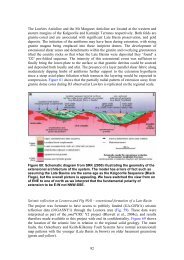
<strong>Uranium</strong> <strong>ore</strong>-<strong>forming</strong> <strong>systems</strong> <strong>of</strong> <strong>the</strong> Lake Frome regionWe have not considered changes in permeabilities and porosities that might have resulted from <strong>the</strong>reaction between fluids and rocks (cf. Cleverley, 2008).7.2.3.3 Boundary conditions and model variationsThe model was uniformly saturated with fluid, with uninterruptible fluid supply at <strong>the</strong> top <strong>of</strong> <strong>the</strong>model. The top <strong>of</strong> <strong>the</strong> model was fixed at atmospheric pressure (~1 MPa) and 25°C. The initialpressure-temperature conditions were based on hydrostatic pressures and a geo<strong>the</strong>rmal gradient <strong>of</strong>60°/km (drillhole Paralana 1B recorded 109°C at ~1,807 m; Petra<strong>the</strong>rm, 2007). The base <strong>of</strong> <strong>the</strong>model was maintained at constant temperature, determined by <strong>the</strong> initial geo<strong>the</strong>rmal gradient. Noadditional heat flow was specified at <strong>the</strong> base or sides <strong>of</strong> <strong>the</strong> model. For <strong>the</strong> MPI we havespecified a radiogenic heat production <strong>of</strong> 0.00308 x 10 6 W/kg (Neumann, pers. comm., 2008), butthis heat production has not noticeably perturbed <strong>the</strong> average geo<strong>the</strong>rmal gradient for <strong>the</strong> initialtemperature conditions. The sides <strong>of</strong> <strong>the</strong> model were open, and <strong>the</strong> base <strong>of</strong> <strong>the</strong> model was closedwith respect to fluid flow.The main set <strong>of</strong> models was run without fluid overpressure within <strong>the</strong> Cadna-owie Formation(Figs. 7.4 to 7.8). However, it is well known that groundwaters in <strong>the</strong> Cadna-owie Formation arecurrently overpressured, as evident from <strong>the</strong> presence <strong>of</strong> active mound springs in <strong>the</strong> region andartesian water in aquifers <strong>of</strong> <strong>the</strong> GAB (e.g., Radke et al., 2000). To illustrate <strong>the</strong> impact <strong>of</strong> thisphenomenon on <strong>the</strong> overall structure <strong>of</strong> <strong>the</strong> fluid flow model within Pliocene-Pleistocene epochs, aseparate model was created with fluid overpressure (Fig. 7.9) within <strong>the</strong> Cadna-owie Formation,accounting for <strong>the</strong> westward fluid flow at ~1 m y 1 .Routine models were run without reactive-transport but with an added tracer (a non-reactivecomponent dissolved in hydro<strong>the</strong>rmal fluids) to investigate <strong>the</strong> hydrodynamics <strong>of</strong> <strong>the</strong> system inresponse to changes in geometrical (<strong>the</strong> topography and structure) and permeability parameters. In<strong>the</strong> case <strong>of</strong> “single-domain” MPI models, <strong>the</strong> tracer was initially distributed exclusively within <strong>the</strong>coherent MPI rocks on both sides <strong>of</strong> <strong>the</strong> Paralana Fault (Figs. 7.4D to 7.7D); within <strong>the</strong> “layereddomain”models, <strong>the</strong> tracer was introduced exclusively within <strong>the</strong> wea<strong>the</strong>red layer (Figs. 7.7D,7.8D). In both cases, <strong>the</strong> initial concentration <strong>of</strong> tracer within <strong>the</strong> fluid was specified at <strong>the</strong> 10mol kg 1 level. The geochemical rationale behind this approach was to trace <strong>the</strong> fluids from <strong>the</strong>rocks that are <strong>the</strong> assumed sources <strong>of</strong> uranium (granitic rocks, and oxidized granitic rocks,respectively).7.2.4 Representation <strong>of</strong> results – fluid flow modellingTo summarise output results from <strong>the</strong> numerous modelling runs and to facilitate visualcomparison, we present results as follows (Figs. 7.4 to 7.9). Table 7.1 summarises <strong>the</strong> variableschanged throughout <strong>the</strong> presented model set. For each model under discussion, we show plotswith distribution <strong>of</strong> (a) permeabilities, (b) temperatures, (c) instantaneous Darcy fluxes, and(d) distribution <strong>of</strong> <strong>the</strong> tracer. Additionally, plots (a), (b), and (d) show fluid flowlines, but plot (c)shows <strong>the</strong> instantaneous Darcy fluxes and vectors to clearly identify <strong>the</strong> regions where <strong>the</strong> mostfluid flow occurs. All <strong>the</strong> plots are compiled for <strong>the</strong> same time slice (or close time slices fordifferent models, around 10,000 years). The notional locations <strong>of</strong> <strong>the</strong> Four Mile East and Beverleydeposits are shown in Fig. 7.3.Page 85 <strong>of</strong> 151