Brunner USA Instructions - Robeys Ltd
Brunner USA Instructions - Robeys Ltd
Brunner USA Instructions - Robeys Ltd

You also want an ePaper? Increase the reach of your titles
YUMPU automatically turns print PDFs into web optimized ePapers that Google loves.
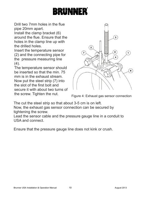
Drill two 7mm holes in the fluepipe 20mm apart.Install the clamp bracket (6)around the flue. Ensure that theholes in the clamp line up withthe drilled holes.Insert the temperature sensor(2) and the connecting pipe forthe pressure measuring line(4).The temperature sensor shouldbe inserted so that the min. 75mm is in the exhaust stream.Now put the steel strip (7) intothe slot of the first bolt andsecure it with about two turns ofthe screw. Tighten the nut.Figure 4: Exhaust gas sensor connectionThe cut the steel strip so that about 3-5 cm is on left.Now, the exhaust gas sensor connection can be secured bytightening the screw.Lead the sensor cable and the pressure gauge line in a conduit to<strong>USA</strong> and connect.Ensure that the pressure gauge line does not kink or crush.<strong>Brunner</strong> <strong>USA</strong> Installation & Operation Manual 10August 2013