Sam Ziemann From - Region of Waterloo
Sam Ziemann From - Region of Waterloo
Sam Ziemann From - Region of Waterloo
Create successful ePaper yourself
Turn your PDF publications into a flip-book with our unique Google optimized e-Paper software.
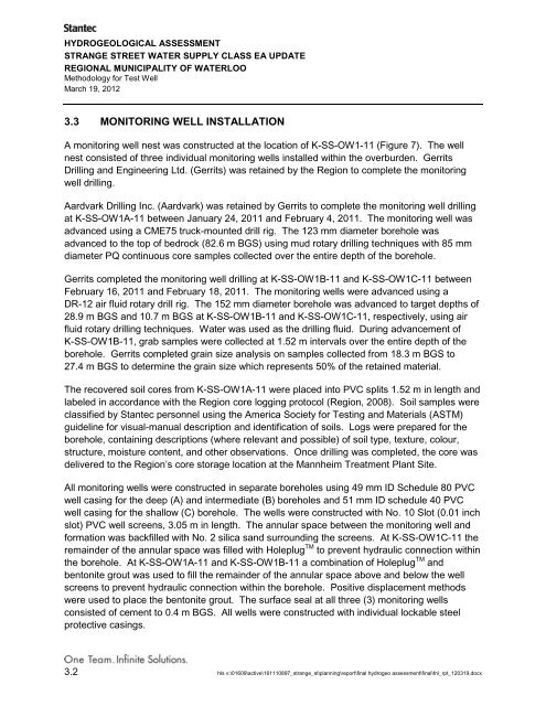
HYDROGEOLOGICAL ASSESSMENTSTRANGE STREET WATER SUPPLY CLASS EA UPDATEREGIONAL MUNICIPALITY OF WATERLOOMethodology for Test WellMarch 19, 20123.3 MONITORING WELL INSTALLATIONA monitoring well nest was constructed at the location <strong>of</strong> K-SS-OW1-11 (Figure 7). The wellnest consisted <strong>of</strong> three individual monitoring wells installed within the overburden. GerritsDrilling and Engineering Ltd. (Gerrits) was retained by the <strong>Region</strong> to complete the monitoringwell drilling.Aardvark Drilling Inc. (Aardvark) was retained by Gerrits to complete the monitoring well drillingat K-SS-OW1A-11 between January 24, 2011 and February 4, 2011. The monitoring well wasadvanced using a CME75 truck-mounted drill rig. The 123 mm diameter borehole wasadvanced to the top <strong>of</strong> bedrock (82.6 m BGS) using mud rotary drilling techniques with 85 mmdiameter PQ continuous core samples collected over the entire depth <strong>of</strong> the borehole.Gerrits completed the monitoring well drilling at K-SS-OW1B-11 and K-SS-OW1C-11 betweenFebruary 16, 2011 and February 18, 2011. The monitoring wells were advanced using aDR-12 air fluid rotary drill rig. The 152 mm diameter borehole was advanced to target depths <strong>of</strong>28.9 m BGS and 10.7 m BGS at K-SS-OW1B-11 and K-SS-OW1C-11, respectively, using airfluid rotary drilling techniques. Water was used as the drilling fluid. During advancement <strong>of</strong>K-SS-OW1B-11, grab samples were collected at 1.52 m intervals over the entire depth <strong>of</strong> theborehole. Gerrits completed grain size analysis on samples collected from 18.3 m BGS to27.4 m BGS to determine the grain size which represents 50% <strong>of</strong> the retained material.The recovered soil cores from K-SS-OW1A-11 were placed into PVC splits 1.52 m in length andlabeled in accordance with the <strong>Region</strong> core logging protocol (<strong>Region</strong>, 2008). Soil samples wereclassified by Stantec personnel using the America Society for Testing and Materials (ASTM)guideline for visual-manual description and identification <strong>of</strong> soils. Logs were prepared for theborehole, containing descriptions (where relevant and possible) <strong>of</strong> soil type, texture, colour,structure, moisture content, and other observations. Once drilling was completed, the core wasdelivered to the <strong>Region</strong>’s core storage location at the Mannheim Treatment Plant Site.All monitoring wells were constructed in separate boreholes using 49 mm ID Schedule 80 PVCwell casing for the deep (A) and intermediate (B) boreholes and 51 mm ID schedule 40 PVCwell casing for the shallow (C) borehole. The wells were constructed with No. 10 Slot (0.01 inchslot) PVC well screens, 3.05 m in length. The annular space between the monitoring well andformation was backfilled with No. 2 silica sand surrounding the screens. At K-SS-OW1C-11 theremainder <strong>of</strong> the annular space was filled with Holeplug TM to prevent hydraulic connection withinthe borehole. At K-SS-OW1A-11 and K-SS-OW1B-11 a combination <strong>of</strong> Holeplug TM andbentonite grout was used to fill the remainder <strong>of</strong> the annular space above and below the wellscreens to prevent hydraulic connection within the borehole. Positive displacement methodswere used to place the bentonite grout. The surface seal at all three (3) monitoring wellsconsisted <strong>of</strong> cement to 0.4 m BGS. All wells were constructed with individual lockable steelprotective casings.3.2 hls v:\01609\active\161110897_strange_st\planning\report\final hydrogeo assessment\final\fnl_rpt_120319.docx


