- Page 1 and 2: ®Established 1981Advanced Test Equ
- Page 3 and 4: Copyright Tektronix, Inc. All righ
- Page 7 and 8: Table of ContentsRemote ControlHard
- Page 9 and 10: Table of ContentsIndexLocal control
- Page 11 and 12: Table of ContentsFigure 2-35: ALARM
- Page 13 and 14: Table of ContentsList of TablesTabl
- Page 15 and 16: Table of ContentsxDDS200 Digital De
- Page 17 and 18: General Safety SummaryProvide Prope
- Page 19: PrefacexivDDS200 Digital Demodulati
- Page 22 and 23: Preparation for UseFront PanelFront
- Page 24 and 25: Preparation for UseTable 1-1: Legen
- Page 26 and 27: Preparation for UseTable 1-2: Legen
- Page 28 and 29: Preparation for UseUnpacking the Un
- Page 30 and 31: Preparation for UsePositioning the
- Page 32 and 33: Preparation for UsePowering OnConne
- Page 34 and 35: Preparation for UseInitial update -
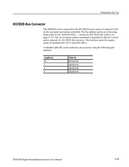
- Page 38: Preparation for Use1-18 DDS200 Digi
- Page 41 and 42: Manual OperationSample SettingThis
- Page 43 and 44: Manual OperationFigure 2-3: MODE me
- Page 45 and 46: Manual OperationPress the RECEIVER
- Page 47 and 48: Manual OperationBasic OperationThe
- Page 49 and 50: Manual OperationFigure 2-7: MEASURE
- Page 51 and 52: Manual OperationSoft KeysThe soft k
- Page 53 and 54: Manual OperationNumeric KeypadSelec
- Page 55 and 56: Manual OperationPresetting the Unit
- Page 57 and 58: Manual OperationFigure 2-14: RECALL
- Page 59 and 60: Manual OperationThe display mode do
- Page 61 and 62: Manual OperationFigure 2-18: SETUP:
- Page 63 and 64: Manual OperationThe type of printer
- Page 65 and 66: Manual OperationOperation as Demodu
- Page 67 and 68: Manual OperationFigure 2-24: INPUT:
- Page 69 and 70: Manual OperationFigure 2-26: STO: E
- Page 71 and 72: Manual Operation84QAM16QAM32QAM64QA
- Page 73 and 74: Manual OperationSPECIAL FUNCTION Me
- Page 75 and 76: Manual OperationA wide loop bandwid
- Page 77 and 78: Manual OperationALARM MenuThis subs
- Page 79 and 80: Manual OperationPressing the ALARM
- Page 81 and 82: Manual OperationFigure 2-34: ALARM:
- Page 83 and 84: Manual OperationThe alarm register
- Page 85 and 86: Manual OperationMEASURE MenuThe DDS
- Page 87 and 88:
Manual OperationFor further informa
- Page 89 and 90:
Manual OperationConstellation Diagr
- Page 91 and 92:
Manual OperationFigure 2-42 shows a
- Page 93 and 94:
Manual OperationQAM Parameters. Whe
- Page 95 and 96:
Manual OperationNOTE. For reading o
- Page 97 and 98:
Manual OperationPreset Values and M
- Page 99 and 100:
Manual OperationTable 2-4: DDS200 P
- Page 101 and 102:
Manual OperationExamples of Applica
- Page 103 and 104:
Manual OperationFigure 2-48: Conste
- Page 105 and 106:
Manual OperationThe magnitude of th
- Page 107 and 108:
Manual OperationFigure 2-53: Conste
- Page 109 and 110:
Manual OperationFrequency of occurr
- Page 111 and 112:
Manual OperationFrom the standard d
- Page 113 and 114:
Manual OperationTable 2-5: Theoreti
- Page 115 and 116:
Manual OperationThe term “modulat
- Page 117 and 118:
Manual OperationAmplitude N = 2 4 -
- Page 119 and 120:
Manual OperationBER Measurement wit
- Page 121 and 122:
Manual Operationare taken into acco
- Page 123 and 124:
Manual OperationIt should be noted
- Page 125 and 126:
Manual OperationThe key characteris
- Page 127:
Manual OperationThe key characteris
- Page 130 and 131:
Remote Control
- Page 132 and 133:
Remote ControlIEC/IEEE-Bus Messages
- Page 134 and 135:
Remote ControlCommon commands. Comm
- Page 136 and 137:
Remote ControlNumeric suffix:If an
- Page 138 and 139:
Remote ControlExample: Special n
- Page 140 and 141:
Remote ControlParameter:In the para
- Page 142 and 143:
Remote Control*CLS*ESE 0 to 255*ESR
- Page 144 and 145:
Remote ControlInstrument Model and
- Page 146 and 147:
Remote ControlOutput UnitThe output
- Page 148 and 149:
Remote ControlCONDition register. T
- Page 150 and 151:
Remote ControlOverview of StatusReg
- Page 152 and 153:
Remote ControlTable 3-2: Definition
- Page 154 and 155:
Remote ControlTable 3-5: Definition
- Page 156:
Remote ControlResetting the StatusR
- Page 159 and 160:
Maintenance and TroubleshootingRepl
- Page 161:
Maintenance and TroubleshootingTabl
- Page 164 and 165:
Appendix A: SpecificationsTable A-1
- Page 166 and 167:
Appendix A: SpecificationsTable A-2
- Page 168 and 169:
Appendix A: SpecificationsA-6 DDS20
- Page 170 and 171:
Appendix B: IEC/IEEE-Bus InterfaceS
- Page 172 and 173:
Appendix B: IEC/IEEE-Bus InterfaceT
- Page 174 and 175:
Appendix C: List of Error MessagesT
- Page 176 and 177:
Appendix C: List of Error MessagesT
- Page 178 and 179:
Appendix C: List of Error MessagesT
- Page 180 and 181:
Appendix C: List of Error MessagesD
- Page 182 and 183:
Appendix D: List of CommandsSTATus
- Page 184 and 185:
Appendix D: List of CommandsSYSTem
- Page 186 and 187:
Appendix D: List of CommandsINPut S
- Page 188 and 189:
Appendix D: List of CommandsTable D
- Page 190 and 191:
Appendix D: List of CommandsTable D
- Page 192 and 193:
Appendix D: List of CommandsREAD Su
- Page 194 and 195:
Appendix D: List of CommandsTable D
- Page 196 and 197:
Appendix D: List of CommandsTable D
- Page 198 and 199:
Appendix D: List of CommandsTable D
- Page 200 and 201:
Appendix D: List of CommandsD-20 DD
- Page 202 and 203:
Appendix E: Programming ExamplesSen
- Page 204 and 205:
Appendix E: Programming ExamplesSer
- Page 206 and 207:
Appendix E: Programming Examples
- Page 208 and 209:
Appendix F: Remote Control via RS-2
- Page 210 and 211:
Appendix F: Remote Control via RS-2
- Page 212 and 213:
Appendix F: Remote Control via RS-2
- Page 214:
Appendix F: Remote Control via RS-2
- Page 217 and 218:
IndexHHandshake, RS232, F-5Hard key
- Page 219:
IndexSetting device address, 3-2Set