Twido Programmable controller
Twido programmable controller - Mejdaf Group
Twido programmable controller - Mejdaf Group
- No tags were found...

Create successful ePaper yourself
Turn your PDF publications into a flip-book with our unique Google optimized e-Paper software.
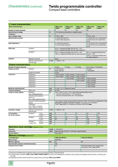
Characteristics (continued)<br />
<strong>Twido</strong> programmable <strong>controller</strong> 0<br />
Compact base <strong>controller</strong>s<br />
c input characteristics<br />
Base <strong>controller</strong> type<br />
TWD LCpA<br />
10DRF<br />
TWD LCpA<br />
16DRF<br />
TWD LCpA<br />
24DRF<br />
TWD LCpA<br />
40DRF<br />
Number of input channels 6 9 14 24<br />
Nominal input voltage V c 24 sink/source (positive or negative logic)<br />
Commons 1 2<br />
Input voltage range V c 20.4...28.8 c 20.4...26.4<br />
Nominal input current<br />
Input impedance<br />
11 mA for I0.0 and I0.1,<br />
7 mA for other inputs I0.i<br />
2.1 kΩ for I0.0 and I0.1,<br />
3.4 kΩ for other inputs I0.i<br />
TWD LCpE<br />
40DRF<br />
11 mA for I0.0, I0.1, I0.6 and I0.7,<br />
7 mA for I0.2 to I0.5 and I0.8 to<br />
I0.23<br />
2.1 kΩ for I0.0, I0.1, I0.6 and I0.7,<br />
3.4 kΩ for I0.2 to I0.5 and I0.8 to<br />
I0.23<br />
Filter time At state 1 35 μs + programmed fi lter time for I0.0…I0.5,<br />
40 μs + programmed fi lter time for other inputs I0.i<br />
At state 0<br />
45 μs + programmed fi lter time for I0.0…I0.5,<br />
150 μs + programmed fi lter time for other inputs I0.i<br />
40 μs + programmed fi lter time<br />
for I0.0…I0.5,<br />
150 μs + programmed fi lter time<br />
for other inputs I0.i<br />
Isolation Between channels None<br />
Between channels and<br />
internal logic<br />
V rms a 500 for 1 min<br />
Output characteristics<br />
Number of output channels 4 relay 7 relay 10 relay 16 (14 relay + 2 transistor)<br />
Output currents Nominal A 2 per channel,<br />
8 per common<br />
2 (relay)<br />
1 (transistor)<br />
Surge per channel 5 max. –<br />
Commons Common 0 3 N/O contacts 4 N/O contacts 4 N/O contacts –<br />
Common 1 1 N/O contact 2 N/O contacts 4 N/O contacts –<br />
Common 2 – 1 N/O contact 1 N/O contact 4 N/O contacts<br />
Common 3 – – 1 N/O contact 4 N/O contacts<br />
Common 4 – – – 4 N/O contacts<br />
Common 5 – – – 1 N/O contact<br />
Common 6 – – – 1 N/O contact<br />
Minimum switching load mA 0.1 per c 0.1 V (reference value)<br />
Contact resistance When new mΩ 30 max<br />
Loads on relay outputs<br />
Insulation voltage<br />
Consumption<br />
for all the outputs<br />
Resistive<br />
(e.g.: heating element)<br />
inductive with protection<br />
device (1)<br />
(e.g.: relay, solenoid valve)<br />
Inductive without protection<br />
device<br />
Capacitive<br />
(e.g.: TeSys U starters,<br />
Festo solenoid valves)<br />
Between channels and<br />
internal logic<br />
A 2 at a 240 V or 2 at c 30 V (with 1800 operations/hour max.):<br />
- minimum electrical life: 1 x 10 5 operations<br />
- minimum mechanical life: 20 x 10 6 operations<br />
V rms<br />
Use of relay outputs not guaranteed (reduction of life). For this type of application, it is<br />
advisable to use the transistor outputs of compact base <strong>controller</strong>s<br />
TWD LCpp 40DRF or of extension modules TM2 DDO pppp<br />
a 500 for 1 min<br />
At state 0 c 5 V mA 5 5 5 70 170<br />
c 24 V mA – – – 5 5<br />
At state 1 c 5 V mA 24 30 36 90 190<br />
c 24 V mA 26 40 55 128 128<br />
At state 1<br />
+ inputs ON<br />
c 5 V mA – – – 140 240<br />
c 24 V mA – – – 128 128<br />
Real-time clock cartridge (optional) (2) (3)<br />
Precision s/mth. + 30 at 25 °C<br />
Autonomy days approximately 30 at 25 °C with fully charged battery<br />
Backup battery See page 10<br />
Memory cartridge (optional) (2)<br />
Cartridge type TWD XCP MFK32 TWD XCP MFK64<br />
Memory type<br />
EEPROM<br />
Memory capacity Kb 32 64<br />
Save/transfer program and internal words<br />
Yes<br />
Program size increase No 6000 instructions with compact base<br />
<strong>controller</strong>s TWD LCpp 40DRF<br />
(1) Inductive load fi tted with a protection device such as an RC peak limiter or fl ywheel diode.<br />
(2) Compact base <strong>controller</strong>s TWD LCpA 10DRF/16DRF/24DRF have only one cartridge slot, therefore only one type of cartridge (real-time clock or memory) can<br />
be used.<br />
(3) Integrated real-time clock function for compact base <strong>controller</strong>s TWD LCpp 40DRF.<br />
12