Twido Programmable controller
Twido programmable controller - Mejdaf Group
Twido programmable controller - Mejdaf Group
- No tags were found...

You also want an ePaper? Increase the reach of your titles
YUMPU automatically turns print PDFs into web optimized ePapers that Google loves.
Recommendations for<br />
setup<br />
<strong>Twido</strong> programmable <strong>controller</strong><br />
Analog I/O extension modules<br />
Electromagnetic compatibility<br />
1<br />
2<br />
2<br />
4<br />
1<br />
3<br />
Connections for ensuring conformity to EMC standards<br />
Principle<br />
In order to protect against external interference, cables and cordsets carrying the<br />
signals below must be shielded:<br />
b Extension modules:<br />
v Sensors and actuators connected to TM2 AMI/ARI and TM2 ApO/ApM analog I/O<br />
v CANopen bus<br />
b <strong>Twido</strong> <strong>controller</strong> base:<br />
v Sensors connected to inputs with low fi ltering<br />
v Serial links.<br />
3<br />
4<br />
The use of shielded cables requires compliance with the following wiring rules:<br />
b Shielding earthed at both ends of the cables. Metal conduit or ducting can be used<br />
for part of the shielding length, provided there is no break in the continuity of the<br />
ground connections.<br />
b Wherever possible, keep cables carrying signals of different categories separate..<br />
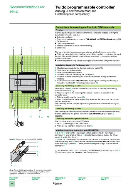
Installation diagram for <strong>Twido</strong> <strong>controller</strong><br />
1 Metal plate connected to the device's protective earth (PE)<br />
2 <strong>Twido</strong> programmable <strong>controller</strong><br />
3 Analogue I/O extension module<br />
4 Shielded cables for connecting the fast inputs 4<br />
8 Shielded cable for connecting the sensors/actuators on analogue extension<br />
modules<br />
9 Earth connection plate TM2 XMTGB for attaching and earthing the shielding of<br />
the cables numbered 8 in the diagram (see detail A)<br />
Connecting the shielding of cables 4<br />
5<br />
6<br />
7<br />
7<br />
15<br />
9<br />
8<br />
A 13<br />
Shielding of cables 4 (connection of sensors/actuators to the base) via shielding<br />
connection clamp 15 (1):<br />
v Attach and ground the shielding of the cables 4 as close as possible to the<br />
<strong>controller</strong> base.<br />
v Strip the shielding (at the clamp 15).<br />
v Attach the cable to the metal support 1 by tightening the clamp onto the stripped<br />
part of the shielding.<br />
The shielding must be clamped tightly enough to the metal support to ensure good<br />
contact.<br />
Connecting the shielding of cables 8<br />
The shielding for cables 8 (connection of the extension modules' sensors/actuators)<br />
must be attached to the ground connection plate TM2 XMTGB (see detail A<br />
opposite)<br />
Connecting the functional ground terminals<br />
The functional ground terminals (FG) of the:<br />
v 24 V c power supply of the <strong>Twido</strong> base<br />
v Analogue I/O extension modules, see detail A.<br />
8<br />
9<br />
Detail A: Ground connection plate TM2 XMTGB<br />
13<br />
14<br />
10<br />
11<br />
12<br />
Installing the ground connection plate TM2 XMTGB<br />
v 8, 9, 10, 11 and 12: The shielding on cable 8 is stripped at the male Faston<br />
connector 10 for a length of 15 mm 11, then tightly clamped on it using the Rilsan<br />
clamp 12 (width 2.5…3 mm).<br />
v 13 and 14: Functional ground terminal (FG). Each earth terminal on the extension<br />
modules (analog and counter) must be connected to the TM2 XMTGB plate 9 via an<br />
earth braid 13 (2) (width W 2…5 mm, thickness W/5) and using a 6.35 mm Faston<br />
connector 14 .<br />
___________________________________________________________________________<br />
(1) The shielding of cables 4 can be attached to plate TM2 XMTGB, in the same way as cable 8.<br />
(2) Earth braid supplied with TM2 ARI 8LT/LRJ analog modules.<br />
10<br />
9 8<br />
Note: These shielding connections do not remove the need to<br />
connect the PE protective conductors (green-yellow) to the<br />
appropriate terminals on each unit or product.<br />
Presentation:<br />
page 50<br />
Description:<br />
page 50<br />
Characteristics:<br />
pages 51 …<br />
References:<br />
page 54<br />
Dimensions:<br />
page 55<br />
56