m return - mbm-Service GmbH
m return - mbm-Service GmbH
m return - mbm-Service GmbH

You also want an ePaper? Increase the reach of your titles
YUMPU automatically turns print PDFs into web optimized ePapers that Google loves.
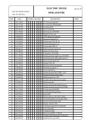
3. ELECTRICAL CONNECTION<br />
• The appliance must be connected to the mains power supply<br />
in compliance with current regulations.<br />
• Before connecting the appliance to the mains supply, make<br />
sure that the voltage and frequency shown on the appliance<br />
rating plate correspond with that of the power supply.<br />
• The appliance must be permanently connected to the mains<br />
power supply with an H05 RN-F type cable. The power supply<br />
cable must be protected by a metal or rigid plastic tube. If the<br />
appliance is connected by way of an existing lead, do not insert<br />
the installation tube in the appliance and make sure the tube<br />
has no sharp edges.<br />
• A safety cutout switch of suitable capacity with a contact<br />
breaking distance of at least 3 mm must be fitted upstream of<br />
the appliance.<br />
This cutout switch must be installed near the appliance in the<br />
permanent electrical system of the premises.<br />
• The appliance must be suitably earthed. The earthing conductor<br />
must therefore be connected to the terminal marked G on<br />
the connection terminal board. The appliance must also be<br />
connected to an equipotential system.<br />
This connection is made using the stop screw marked E<br />
located on the outside of the appliance near the power cable<br />
inlet.<br />
The equipotential wire must have a minimum cross-section of<br />
10 mm 2 .<br />
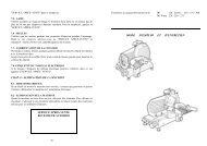
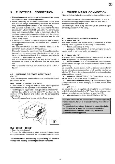
4.1 INSTALLING THE POWER SUPPLY CABLE<br />
(Fig. "10")<br />
To access the power supply cable connection terminal board,<br />
proceed as follows:<br />
Mod. 6 GN1/1 - 10 GN1/1 - 10 GN2/1<br />
• Undo screws "V" fixing the terminal board support panel located<br />
underneath the appliance on the front LH side.<br />
• Feed the power supply cable through cable clamp inlet "B".<br />
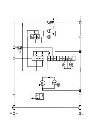
• Connect the cable to terminal board “A” as shown in the<br />
enclosed wiring diagram and fasten with the corresponding<br />
cable clamp.<br />
• Remount the panel and secure with the fixing screws.<br />
10<br />
Mod. 20 GN1/1 - 20 GN2/1<br />
• Open the control panel.<br />
• Connect the cable to terminal board as shown in the enclosed<br />
wiring diagram and fasten with the corresponding cable clamp.<br />
The manufacturer declines any responsibility for failure to<br />
comply with existing accident prevention standards.<br />
41<br />
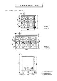
4. WATER MAINS CONNECTION<br />
(Refer to the installation diagrams at the beginning of this booklet).<br />
The appliance is fitted with two separate water inlets ("B" and "N").<br />
The water lines supplying both inlets must be fitted with a<br />
mechanical filter and shut-off cock.<br />
Before fitting the filters, pump water through the system to expel<br />
any solid particles from the piping.<br />
4.1. WATER SUPPLY CHARACTERISTICS<br />
4.1.1 Water inlet "N".<br />
The steam condensation system must be connected to a cold<br />
drinking water supply with the following characteristics:<br />
- total hardness: up to 40°F;<br />
- pressure: 150 to 250 kPa (1.5-2.5 bar); higher pressure<br />
values result in increased water consumption.<br />
4.1.2 Water inlet "B".<br />
The steam production system must be connected to a drinking<br />
water supply with the following characteristics:<br />
- total hardness: 0.5 to 5 °F to prevent the build-up of limescale<br />
inside the boiler (or oven chamber on models with automatic<br />
generation).<br />
On request the oven is supplied with an optional water softener<br />
device with automatic regeneration which must be installed on<br />
inlet line "B". This device is also supplied with a resin sterilisation<br />
kit (available on request).<br />
- pressure: 150 to 250 kPa (1.5-2.5 bar); higher pressure<br />
values result in increased water consumption.<br />
- chlorine ion concentration (Cl -): not more than ~10 ppm<br />
(acceptable value) to avoid damaging the oven's internal steel<br />
elements.<br />
- pH: over 7.<br />
On request the oven is supplied with an optional special filtration<br />
unit which is installed on inlet line "B". This unit also acts as a water<br />
softener by reducing water hardness to less than 5°F.<br />
- electrical conductivity: 50 to 2000 µS/cm (20°C).<br />
Important: Only install the water treatment systems supplied by<br />
the manufacturer. Failure to do so automatically invalidates the<br />
guarantee.<br />
The use of dosing systems designed to prevent the buildup<br />
of lime-scale in pipes (i.e. polyphosphate dosing<br />
systems) is also prohibited since it may impair the<br />
performance of the appliance.<br />
GB