ÿþþ ÿ R O - C A N - I N T E R F A C E ...
ÿþþ ÿ R O - C A N - I N T E R F A C E ...
ÿþþ ÿ R O - C A N - I N T E R F A C E ...

Create successful ePaper yourself
Turn your PDF publications into a flip-book with our unique Google optimized e-Paper software.
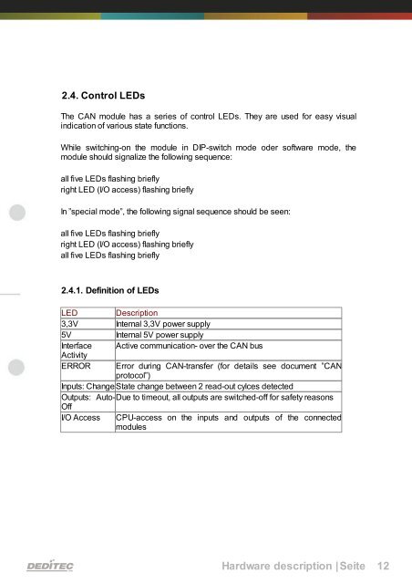
2.4. Control LEDs<br />
The CAN module has a series of control LEDs. They are used for easy visual<br />
indication of various state functions.<br />
While switching-on the module in DIP-switch mode oder software mode, the<br />
module should signalize the following sequence:<br />
all five LEDs flashing briefly<br />
right LED (I/O access) flashing briefly<br />
In ”special mode”, the following signal sequence should be seen:<br />
all five LEDs flashing briefly<br />
right LED (I/O access) flashing briefly<br />
all five LEDs flashing briefly<br />
2.4.1. Definition of LEDs<br />
LED Description<br />
3,3V Internal 3,3V power supply<br />
5V Internal 5V power supply<br />
Interface Active communication- over the CAN bus<br />
Activity<br />
ERROR Error during CAN-transfer (for details see document ”CAN<br />
protocol”)<br />
Inputs: Change State change between 2 read-out cylces detected<br />
Outputs: Auto-Due<br />
to timeout, all outputs are switched-off for safety reasons<br />
Off<br />
I/O Access CPU-access on the inputs and outputs of the connected<br />
modules<br />
Hardware description |Seite 12