ÿþþ ÿ R O - C A N - I N T E R F A C E ...
ÿþþ ÿ R O - C A N - I N T E R F A C E ...
ÿþþ ÿ R O - C A N - I N T E R F A C E ...

You also want an ePaper? Increase the reach of your titles
YUMPU automatically turns print PDFs into web optimized ePapers that Google loves.
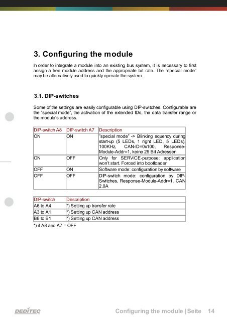
3. Configuring the module<br />
In order to integrate a module into an existing bus system, it is necessary to first<br />
assign a free module address and the appropriate bit rate. The ”special mode”<br />
may be alternatively used to quickly operate the system.<br />
3.1. DIP-switches<br />
Some of the settings are easily configurable using DIP-switches. Configurable are<br />
the ”special mode”, the activation of the extended IDs, the data transfer range or<br />
the module’s address.<br />
DIP-switch A8 DIP-switch A7 Description<br />
ON ON ”special mode” -> Blinking squency during<br />
start-up (5 LEDs, 1 right LED, 5 LEDs),<br />
100KHz, CAN-ID=0x100, Response-<br />
Module-Addr=1, keine 29 Bit Adressen<br />
ON OFF Only for SERVICE-purpose: application<br />
won’t start. Forced into bootloader<br />
OFF ON Software mode: configuration by software<br />
OFF OFF DIP-switch mode: configuration by DIP-<br />
Switches, Response-Module-Addr=1, CAN<br />
2.0A<br />
DIP-switch Description<br />
A6 to A4 *) Setting up transfer rate<br />
A3 to A1 *) Setting up CAN address<br />
B8 to B1 *) Setting up CAN address<br />
*) if A8 and A7 = OFF<br />
Configuring the module |Seite 14