Deliverables and Services - IHP Microelectronics
Deliverables and Services - IHP Microelectronics
Deliverables and Services - IHP Microelectronics

Create successful ePaper yourself
Turn your PDF publications into a flip-book with our unique Google optimized e-Paper software.
A u S G e w ä H L t e p r o J e K t e – S e L e C t e d p r o J e C t S<br />
Es wurde ein neues Konzept für ein Referenz-Netzwerk,<br />
welches bisher aus der Literatur nicht bekannt war,<br />
entwickelt, um bestimmte technologische Beschränkungen<br />
des konventionellen Netzwerks zu umgehen.<br />
Die Idee ist in Abb. 15 dargestellt und besteht darin,<br />
ein Parallel-Netzwerk statt eines üblichen seriellen zu<br />
verwenden. Das vorgeschlagene Netzwerk hat eine um<br />
den Faktor zwei größere B<strong>and</strong>breite und die zusätzliche<br />
Möglichkeit zur elektrischen Kalibrierung, die beim<br />
konventionellen Netzwerk nicht möglich ist.<br />
Der zweite anspruchsvolle Block ist der Komparator. Er<br />
wurde in die Richtungen Geschwindigkeit (B<strong>and</strong>breite)<br />
und Empfindlichkeit optimiert. Ein Begrenzerverstärker,<br />
basierend auf einer Cherry-Hooper-Architektur,<br />
wurde dem Komparator vorgeschaltet, um seine korrekte<br />
Funktion auch unter Übersteuerung zu sichern.<br />
Die simulierte Empfindlichkeit des Komparators ist weniger<br />
als ½ LSB bei 5 GHz Frequenz.<br />
Der ADU mit dem vorgeschlagenen Referenz-Netzwerk<br />
wurde gefertigt und gemessen. Das Chipfoto ist in<br />
Abb. 16 dargestellt. Die Messungen zeigen, dass die<br />
statischen Fehler INL und DNL kleiner als ½ LSB sind.<br />
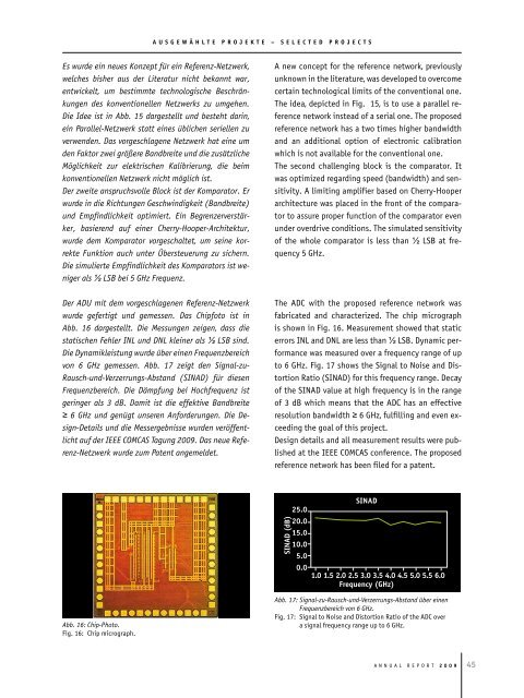
Die Dynamikleistung wurde über einen Frequenzbereich<br />
von 6 GHz gemessen. Abb. 17 zeigt den Signal-zu-<br />
Rausch-und-Verzerrungs-Abst<strong>and</strong> (SINAD) für diesen<br />
Frequenzbereich. Die Dämpfung bei Hochfrequenz ist<br />
geringer als 3 dB. Damit ist die effektive B<strong>and</strong>breite<br />
≥ 6 GHz und genügt unseren Anforderungen. Die Design-Details<br />
und die Messergebnisse wurden veröffentlicht<br />
auf der IEEE COMCAS Tagung 2009. Das neue Referenz-Netzwerk<br />
wurde zum Patent angemeldet.<br />
Abb. 16: Chip-Photo.<br />
Fig. 16: Chip micrograph.<br />
A new concept for the reference network, previously<br />
unknown in the literature, was developed to overcome<br />
certain technological limits of the conventional one.<br />
the idea, depicted in Fig. 15, is to use a parallel reference<br />
network instead of a serial one. the proposed<br />
reference network has a two times higher b<strong>and</strong>width<br />
<strong>and</strong> an additional option of electronic calibration<br />
which is not available for the conventional one.<br />
the second challenging block is the comparator. It<br />
was optimized regarding speed (b<strong>and</strong>width) <strong>and</strong> sensitivity.<br />
A limiting amplifier based on Cherry-Hooper<br />
architecture was placed in the front of the comparator<br />
to assure proper function of the comparator even<br />
under overdrive conditions. the simulated sensitivity<br />
of the whole comparator is less than ½ lSB at frequency<br />
5 GHz.<br />
the ADC with the proposed reference network was<br />
fabricated <strong>and</strong> characterized. the chip micrograph<br />
is shown in Fig. 16. Measurement showed that static<br />
errors Inl <strong>and</strong> Dnl are less than ½ lSB. Dynamic performance<br />
was measured over a frequency range of up<br />
to 6 GHz. Fig. 17 shows the Signal to noise <strong>and</strong> Distortion<br />
Ratio (SInAD) for this frequency range. Decay<br />
of the SInAD value at high frequency is in the range<br />
of 3 dB which means that the ADC has an effective<br />
resolution b<strong>and</strong>width ≥ 6 GHz, fulfilling <strong>and</strong> even exceeding<br />
the goal of this project.<br />
Design details <strong>and</strong> all measurement results were published<br />
at the Ieee CoMCAS conference. the proposed<br />
reference network has been filed for a patent.<br />
Abb. 17: Signal-zu-Rausch-und-Verzerrungs-Abst<strong>and</strong> über einen<br />
Frequenzbereich von 6 GHz.<br />
Fig. 17: Signal to noise <strong>and</strong> Distortion Ratio of the ADC over<br />
a signal frequency range up to 6 GHz.<br />
A n n u A l R e p o R t 2 0 0 9