Multipactor in Low Pressure Gas and in ... - of Richard Udiljak
Multipactor in Low Pressure Gas and in ... - of Richard Udiljak
Multipactor in Low Pressure Gas and in ... - of Richard Udiljak
Create successful ePaper yourself
Turn your PDF publications into a flip-book with our unique Google optimized e-Paper software.
S<strong>in</strong>ce the equation has the same form as Eq. (3.1), it will also have the<br />
same solutions <strong>and</strong> as the <strong>in</strong>itial conditions are identical, the formulas<br />
for the resonant field amplitude <strong>and</strong> the impact velocity will be identical.<br />
However, it should be noted that <strong>in</strong>stead <strong>of</strong> νc one will have ν <strong>and</strong> v0<br />
should be replaced by u0. An important difference is that the velocity<br />
<strong>in</strong> the previous model was only directed <strong>in</strong> the x-direction, but now<br />
there is also a thermal velocity component, vt, i.e. the total velocity<br />
is v = u + vt. With these new designations, the expressions for the<br />
resonant field amplitude <strong>and</strong> the impact velocity become:<br />
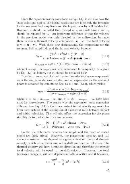
E0 =<br />
m<br />
e (ω2 + ν2 )(d + u0<br />
ν (Φ − 1))<br />
(1 + Φ)s<strong>in</strong> α + ((1 − Φ) ω<br />
ν<br />
2ν + ω )cos α<br />
(3.11)<br />
uimpact = u0Φ + Λ(1 + Φ)(ω cos α − ν s<strong>in</strong>α) (3.12)<br />
where Φ = exp (−Nπν/ω) has been <strong>in</strong>troduced for simplicity. Λ is given<br />
by Eq. (3.4) as before, but νc should be replaced by ν.<br />
In order to construct the multipactor boundaries, the same approach<br />
as <strong>in</strong> the simple model case is taken <strong>and</strong> an expression for the resonant<br />
phase is obta<strong>in</strong>ed by comb<strong>in</strong><strong>in</strong>g Eqs. (3.11) <strong>and</strong> (3.12), which yields,<br />
tan α = ω2 [ρΦ + χ] + 2ν 2 (Φu0 − uimpact)<br />
(dν + uimpact − u0)νω(1 + Φ)<br />
(3.13)<br />
where ρ = dν + uimpact + u0 <strong>and</strong> χ = dν − uimpact − u0 have been<br />
used for convenience. The reason why the expression looks somewhat<br />
different from Eq. (3.7) is that the constant <strong>in</strong>itial velocity approach has<br />
been used <strong>in</strong>stead <strong>of</strong> the assumption <strong>of</strong> a constant ratio between impact<br />
<strong>and</strong> <strong>in</strong>itial velocities. This will also affect the expression for the phase<br />
stability factor, which <strong>in</strong> this case becomes<br />
G = (Φ − 1)(ν2 + ω 2 )s<strong>in</strong> αΛ − Φνu0<br />
ν((1 + Φ)(ν s<strong>in</strong> α − ω cos α)Λ − Φu0)<br />
(3.14)<br />
So far, the differences between the simple <strong>and</strong> the more advanced<br />
model are fairly trivial. However, the parameters used (νc <strong>and</strong> νiz)<br />
are not constants, they depend to a great extent on the total electron<br />
velocity, which is the vector sum <strong>of</strong> the drift <strong>and</strong> thermal velocities. The<br />
thermal velocity will have a r<strong>and</strong>om direction <strong>and</strong> therefore the average<br />
total velocity will be equal to the drift velocity. However, the total<br />
(average) energy, ɛ, will still depend on both velocities <strong>and</strong> it becomes,<br />
ɛ = mv2<br />
2<br />
= m<br />
2 (u2 + 〈vt 2 〉) (3.15)<br />
45


