

Multipactor in Low Pressure Gas and in ... - of Richard Udiljak
Multipactor in Low Pressure Gas and in ... - of Richard Udiljak
Multipactor in Low Pressure Gas and in ... - of Richard Udiljak

Create successful ePaper yourself
Turn your PDF publications into a flip-book with our unique Google optimized e-Paper software.
upper right region <strong>of</strong> the figures, where the electron growth is very slow.<br />
There is good agreement <strong>in</strong> the general behaviour <strong>and</strong> the transition<br />
from double-sided to s<strong>in</strong>gle-sided multipactor occurs at more or less the<br />
same impedances for the different zones <strong>in</strong> both the PIC-simulation <strong>and</strong><br />
the theoretical data, s<strong>in</strong>ce the non-zero <strong>in</strong>itial velocity <strong>in</strong> the PIC-data<br />
is small relative to the oscillatory velocity.<br />
G<br />
100<br />
90<br />
80<br />
70<br />
60<br />
50<br />
40<br />
30<br />
20<br />
10<br />
0.2 0.4 0.6 0.8 1 1.2 1.4 1.6<br />
Z/Z (Z =50 Ω)<br />
0 0<br />
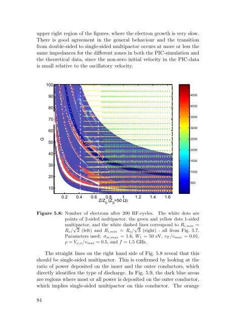
Figure 5.8: Number <strong>of</strong> electrons after 200 RF-cycles. The white dots are<br />
po<strong>in</strong>ts <strong>of</strong> 2-sided multipactor, the green <strong>and</strong> yellow dots 1-sided<br />
multipactor, <strong>and</strong> the white dashed l<strong>in</strong>es correspond to Ri,m<strong>in</strong> =<br />
Ro/ √ 2 (left) <strong>and</strong> Ri,m<strong>in</strong> = Ro/ √ 3 (right) - all from Fig. 5.7.<br />
Parameters used: σse,max = 1.6, W1 = 50 eV, vT/vmax = 0.01,<br />
ρ = Vω,o/vmax = 0.5, <strong>and</strong> f = 1.5 GHz.<br />
The straight l<strong>in</strong>es on the right h<strong>and</strong> side <strong>of</strong> Fig. 5.8 reveal that this<br />
should be s<strong>in</strong>gle-sided multipactor. This is confirmed by look<strong>in</strong>g at the<br />
ratio <strong>of</strong> power deposited on the <strong>in</strong>ner <strong>and</strong> the outer conductors, which<br />
directly identifies the type <strong>of</strong> discharge. In Fig. 5.9, the dark blue areas<br />
are regions where most or all power is deposited on the outer conductor,<br />
which implies s<strong>in</strong>gle-sided multipactor on this conductor. The orange<br />
84<br />
4500<br />
4000<br />
3500<br />
3000<br />
2500<br />
2000<br />
1500<br />
1000<br />
500