
Create successful ePaper yourself
Turn your PDF publications into a flip-book with our unique Google optimized e-Paper software.
<strong>atw</strong> Vol. 62 (<strong>2017</strong>) | Issue 6 ı June<br />
386<br />
AMNT <strong>2017</strong><br />
radiation incidents on the backside<br />
due to the backscattered radiation by<br />
the surrounding drift layers. Therefore,<br />
in order to study the influence<br />
of the backscattered radiation, two<br />
cylindrical detectors (2 cm radius and<br />
0.2 cm length) were modelled in the<br />
phantom (see Fig. 2): one on the front<br />
side (representing a dosimeter worn<br />
in front of the chest) and another one<br />
on the back side (representing a<br />
dosimeter worn at the back side), both<br />
at 10 mm depth to calculate Ḣ p (d).<br />
The personal dose equivalent rate<br />
Ḣ p (d) is calculated as:<br />
Where Ḋ n (E n ) is the neutron absorbed<br />
dose rate, and Ḋ γ (E γ ) is the gamma<br />
absorbed dose rate. The quality factor<br />
for photons (Q γ ) is equal to 1; while<br />
for neutrons (Q n ) it is dependent on<br />
the neutron energy (E n ) and the linear<br />
energy transfer (L) according to:<br />
The MCNP6 energy deposition tally<br />
F6 [Pelowitz et al., 2013] was used to<br />
calculate the absorbed dose rate (D).<br />
Tabulated values for Q n (E n ) were<br />
taken from [Siebert and Schuh macher,<br />
1995] to convert the F6 tally results to<br />
dose equivalents.<br />
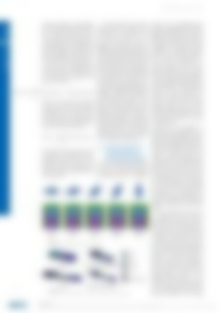
| | Fig. 3.<br />
Different angles of the phantom with respect to POLLUX.<br />
To study the effect the orientation<br />
of the worker with respect to the<br />
shielding cask, five simulations with<br />
the phantom at angles of 0°, 15°,<br />
45°, 60°, and 90° with respect to<br />
POLLUX-10 symmetrical axis (see<br />
Figure 3) were performed in RSD. For<br />
each simulation, the Ḣ p (10) obtained<br />
with the front dosimeter and the sum<br />
of the Ḣ p (10) obtained with the front<br />
and back dosimeter were compared to<br />
check if the use of only one dosimeter<br />
may underestimate the received dose<br />
rate. To reduce the calculation time,<br />
the MCNP6 variance reduction technique<br />
“geometry splitting” [Pelowitz et<br />
al., 2013] was applied. Using geometry<br />
splitting, a weighting is assigned in<br />
the following way: regions near the<br />
tallies (cylindrical detectors in the<br />
phantom) are assigned with a greater<br />
importance than regions farther away.<br />
When a particle leaves a region it is<br />
split/killed according to the importance<br />
ratio adjusting the weight of the<br />
remaining particles to leave the tally<br />
unbiased. A total of 1 · 10 +8 particles<br />
were required per simulation to pass<br />
the ten MCNP6 statistical checks.<br />
2.4 Comparison of Ḣ p (10) in<br />
the rock salt and clay<br />
formation drifts during a<br />
typical working scenario<br />
The above explained methodology,<br />
i.e. the use of two dosimeters for the<br />
estimation of Ḣ p (10) was applied to<br />
the working scenario of POLLUX®<br />
| | Fig. 4.<br />
MCNP6 model of the four steps for a POLLUX® disposal scenario (for details see text).<br />
disposal in the emplacement drift<br />
based on the proposal of DBE TECH-<br />
NOLOGY GmbH [Filbert et al., 1995].<br />
Figure 4 shows the MCNP6 models of<br />
four main working steps in the cask<br />
disposal procedure as well as the main<br />
components. A description of their<br />
geometry can be found in [Bollingerfehr<br />
et al., 2011]. The four steps are:<br />
first the cask is transported on a<br />
carriage through the drift with an<br />
electric locomotive with a driver<br />
sitting inside the cabin (see Fig. 4a).<br />
Once it arrives at the disposal position,<br />
as shown in Fig. 4b, the cask is slowly<br />
positioned under a storage equipment<br />
which elevates the cask from the<br />
carriage to allow locomotive and<br />
carriage to drive back. Once the locomotive<br />
is driven back, the storage<br />
equipment places the cask on the<br />
ground (see Fig. 4c). Finally, as shown<br />
in Fig. 4d, the locomotive moves<br />
the storage equipment to the next<br />
disposal position.<br />
Since the cask geometry of<br />
POLLUX-3M and POLLUX-3U are<br />
equal to that of POLLUX-10, the same<br />
steps as described in Fig. 4 were simulated<br />
for the disposal of POLLUX-10,<br />
POLLUX-3M and POLLUX-3U cask. To<br />
compare the radiation exposure, the<br />
same or a similar amount of SNF<br />
should be disposed in both emplacement<br />
drifts, i.e. one POLLUX-10 cask<br />
in RSD containing fuel rods of one<br />
MOX and nine UOX fuel assemblies<br />
(5.45 tHM) and three casks in CLD<br />
(one POLLUX-3M and two POLLUX-<br />
3U, in total 4.92 tHM). As the working<br />
steps are the same for the disposal<br />
of POLLUX-10, POLLUX-3M and<br />
POLLUX- 3U, Ḣ p (10) was employed to<br />
compare the radiation exposure in the<br />
different working steps as described<br />
above.<br />
The driver sitting inside the cabin<br />
was represented in this study by<br />
the phantom (see Fig. 2). Since the<br />
worker stays all the time inside the<br />
cabin and faces the shielding cask,<br />
the angle between phantom and cask<br />
is always 0°. However, the amount<br />
of backscattered radiation may be<br />
further increased due to the reflection<br />
by the cabin walls and backscattered<br />
neutrons from the drift walls. To<br />
perform the MCNP6 simulations,<br />
geometry splitting was employed in<br />
the drift and inside the locomotive<br />
cabin to reduce the number of transported<br />
particles. To pass the ten<br />
MCNP6 statistical checks, 4 · 10 +8<br />
particles were required for simulation<br />
of the transport and location under<br />
the storage equipment. For the placement<br />
and retreat of the storage<br />
AMNT <strong>2017</strong><br />
Monte-Carlo Based Comparison of the Personal Dose for Emplacement Scenarios of Spent Nuclear Fuel Casks in Generic Deep Geological Repositories ı Héctor Saurí Suárez, Bo Pang, Frank Becker and Volker Metz