ES721 ISO40 7 kW NL - HSD
ES721 ISO40 7 kW NL - HSD
ES721 ISO40 7 kW NL - HSD

Create successful ePaper yourself
Turn your PDF publications into a flip-book with our unique Google optimized e-Paper software.
<strong>HSD</strong><br />
MECHATRONIC<br />
D I V I S I O N<br />
<strong>HSD</strong> S.p.A.<br />
Registered office:<br />
via della meccanica, 16<br />
loc. Chiusa di Ginestreto<br />
61122 Pesaro (PU) ITALY<br />
ES794<br />
Factory headquarters:<br />
p.le Alfio De Simoni, sn<br />
61122 Pesaro (PU) ITALY<br />
Ph.: (+39) 0721 205 211<br />
Fax: (+39) 0721 205 247<br />
E-mail: supporthsd@hsd.it<br />
web: www.hsd.it<br />
5801H0066<br />
EN Rev.01<br />
Instruction manual
<strong>HSD</strong><br />
Table of contents<br />
§ 1 DOCUMENTS SUPPLIED WITH THE PRODUCT........................................................4<br />
§ 2 DOCUMENT INFORMATION........................................................................................4<br />
§ 3 CUSTOMER ASSISTANCE SERVICE..........................................................................4<br />
§ 4 TERMS OF WARRANTY ..............................................................................................5<br />
§ 5 WARNINGS AND SAFETY PRECAUTIONS ................................................................6<br />
5.1 Distribution of this manual ....................................................................................................... 6<br />
5.2 General safety symbols ........................................................................................................... 6<br />
5.3 Risks associated with the electrospindle ................................................................................. 7<br />
5.4 Risks associated with improper use and handling................................................................... 7<br />
5.5 Risks specific to maintenance ................................................................................................. 8<br />
§ 6 TRANSPORT, PACKAGING, UNPACKING, STORAGE .............................................9<br />
6.1 Warnings.................................................................................................................................. 9<br />
6.2 Dimensions and weights.......................................................................................................... 9<br />
6.3 Transport and Packaging Conditions....................................................................................... 9<br />
6.4 Unpacking Procedure .............................................................................................................. 9<br />
6.5 Storage .................................................................................................................................. 10<br />
§ 7 TECHNICAL SPECIFICATIONS .................................................................................11<br />
7.1 Characteristics and performance........................................................................................... 11<br />
§ 8 DIMENSIONS AND MAIN PARTS ..............................................................................13<br />
8.1 Connections........................................................................................................................... 13<br />
8.1.1 DPC & encoder version................................................................................................... 13<br />
8.1.2 Direct liquid coolant coupling & S3 sensor version.......................................................... 15<br />
8.1.3 Deublin distributor, encoder & lateral connections .......................................................... 17<br />
§ 9 INSTALLAZIONE ........................................................................................................19<br />
9.1 Utility supplies in the factory .................................................................................................. 19<br />
9.2 Fixing ..................................................................................................................................... 19<br />
9.3 Hydraulic connections............................................................................................................ 19<br />
9.4 Motor cooling ......................................................................................................................... 19<br />
9.5 Internal tool cooling................................................................................................................ 20<br />
9.5.1 Direct coupling................................................................................................................. 20<br />
9.5.2 Deublin distributor ........................................................................................................... 20<br />
9.5.3 Controlled loss water distributor (DPC) ........................................................................... 20<br />
9.6 External tool cooling .............................................................................................................. 22<br />
9.7 Compressed air specifications............................................................................................... 23<br />
9.8 Pneumatic connections.......................................................................................................... 24<br />
9.9 Example of compressed air circuits ....................................................................................... 24<br />
9.9.1 Tool-holder changing circuit ............................................................................................ 24<br />
9.9.2 Pressurization circuit ....................................................................................................... 24<br />
9.10 automatic cone cleaning...................................................................................................... 25<br />
9.11 Electrical connectors............................................................................................................ 26<br />
§ 10 OPERATION .............................................................................................................27<br />
10.1 General precautions ............................................................................................................ 27<br />
10.2 Running in............................................................................................................................ 27<br />
10.3 Warming up ......................................................................................................................... 27<br />
10.4 Tool locking and release...................................................................................................... 27<br />
10.5 Automatic cleaning of the spindle shaft cone housing......................................................... 28<br />
10.6 Pressurising......................................................................................................................... 28<br />
10.7 Proximity sensors ................................................................................................................ 28<br />
10.7.1 Specifications of proximity sensors ............................................................................... 28<br />
5801H0066 en Rev.01 2/48
<strong>HSD</strong><br />
10.7.2 Electrospindle states and corresponding sensor S1, S2, S5 outputs............................ 29<br />
10.7.3 S3 sensor “shaft idle” (optional)..................................................................................... 29<br />
10.8 Thermal alarm...................................................................................................................... 29<br />
10.9 Encoder (optional) ............................................................................................................... 30<br />
10.9.1 Standard <strong>HSD</strong> TTL rectangular encoder..................................................................... 30<br />
10.10 Choice of toolholder cone.................................................................................................. 31<br />
10.11 Choice of tool..................................................................................................................... 32<br />
10.12 What to do if the tool is blocked on the piece being worked.............................................. 32<br />
§ 11 ORDINARY MAINTENANCE ....................................................................................34<br />
11.1 Daily maintenance ............................................................................................................... 35<br />
11.1.1 Checking and Cleaning the tool holder seat and the tool holder cone .......................... 35<br />
11.1.2 Protection of the tool holder seat................................................................................... 35<br />
11.2 Biweekly Maintenance......................................................................................................... 36<br />
11.2.1 Clean the tool holder cone with ethyl alcohol ................................................................ 36<br />
§ 12 REPLACEMENT OF COMPONENTS .......................................................................37<br />
12.1 Replacement and adjustment of the sensor group .............................................................. 38<br />
12.1.1 Description of the sensor unit........................................................................................ 38<br />
12.1.2 Replacement and adjustment of the sensor unit ........................................................... 39<br />
12.1.3 Sensor S1 adjustment ................................................................................................... 39<br />
12.1.4 Sensor S2 adjustment ................................................................................................... 40<br />
12.1.5 Sensor S5 adjustment ................................................................................................... 41<br />
§ 13 DISPOSING OF THE PRODUCT ..............................................................................42<br />
§ 14 LIST OF SPARE PARTS...........................................................................................43<br />
§ 15 TROUBLESHOOTING ..............................................................................................44<br />
§ 16 DECLARATION OF INCORPORATION ...................................................................47<br />
5801H0066 en Rev.01 3/48
<strong>HSD</strong><br />
§ 1 DOCUMENTS SUPPLIED WITH THE PRODUCT<br />
The documentation supplied with the product includes:<br />
� Manufacturer's declaration as provided for by Appendix IIB of Directive 2006/42/CE.<br />
� Product test certificate.<br />
� This manual, containing the instructions and warnings governing transport, installation, use<br />
and maintenance and final disposal of the product.<br />
i<br />
Check that all the above-mentioned documents are present at the moment the product is<br />
delivered. Copies can be obtained on request from <strong>HSD</strong> S.p.A.<br />
§ 2 DOCUMENT INFORMATION<br />
This manual has been written by the Electrospindle department of the Technical Office at <strong>HSD</strong><br />
S.p.A. for use by all the installers, operators and service engineers who work with the<br />
electrospindle.<br />
ISSUED BY<br />
<strong>HSD</strong> S.p.a<br />
Registered office:<br />
CODE REVISION APPROVED BY<br />
Via della Meccanica, 16;<br />
Loc. Chiusa di Ginestreto<br />
61122 PESARO (PU) ITALY<br />
Factory headquarters:<br />
P.le A. de Simoni, sn<br />
61122 PESARO (PU) ITALY<br />
5801H0066 00 UTE008/05<br />
List of updates<br />
Revision Modified paragraph Description<br />
00 (22.07.2009) - - - New document<br />
01 (29.07.2010) - - - General revision<br />
This manual is delivered as an essential part of the electrospindle and at the time of revision was<br />
the most up to date documentation on the product. For updates please visit our web sites or call<br />
<strong>HSD</strong> Customer Assistance Service (see above)<br />
This document is an English translation of the original manual <strong>HSD</strong> H5801H0066 written in Italian.<br />
In the case of any discrepancies between this translation and the original Italian document,<br />
reference should be made to the original version available on web site www.hsd.it, or from <strong>HSD</strong><br />
Customer Assistance Service (see above).<br />
§ 3 CUSTOMER ASSISTANCE SERVICE<br />
<strong>HSD</strong> S.p.A.<br />
Registered office:<br />
Via della Meccanica 16<br />
61122 PESARO (PU) ITALY<br />
Loc. Chiusa di Ginestreto<br />
Factory headquarters:<br />
P.le A. De Simoni, sn<br />
61122 PESARO (PU) ITALY<br />
Tel. (+39)0721.205.211<br />
Fax (+39)0721.205.247<br />
E-mail supporthsd@hsd.it<br />
Web www.hsd.it<br />
<strong>HSD</strong><br />
Deutschland GmbH<br />
Brückenstrasse 32<br />
D-73037 Göppingen DEUTSCHLAND<br />
Tel. +49(0)7161 / 956660<br />
Fax +49(0)7161 / 9566610<br />
E-mail supporthsddeut@hsddeutschland.de<br />
Web www.hsddeutschland.de<br />
<strong>HSD</strong> USA Inc.<br />
3764 SW, 30 th Avenue<br />
Hollywood, Florida 33312 USA<br />
Phone no. (+1) 954 587 1991<br />
Fax (+1) 954 587 8338<br />
E-mail supporthsdusa@hsd.it<br />
Web www.hsdusa.com<br />
<strong>HSD</strong><br />
Mechatronic<br />
Shangai Co. Ltd<br />
D2, First floor, 207 Taigu Road<br />
Waigaoquiao Free Trade Zone<br />
200131, Shangai - China<br />
Phone no. (+86) 215866 1236<br />
E-mail sales@hsd-china.cn<br />
Web www.hsd-china.cn<br />
5801H0066 en Rev.01 4/48
<strong>HSD</strong><br />
§ 4 TERMS OF WARRANTY<br />
<strong>HSD</strong> S.p.A. guarantees that this electrospindle has been QC passed in testing in the factory.<br />
All work performed under the terms of the warranty shall be carried out at the premises of <strong>HSD</strong><br />
S.p.A., with carriage at the Customer’s expense. <strong>HSD</strong> S.p.A. cannot accept any responsibility for<br />
production losses incurred as a result of work performed under the warranty.<br />
The warranty does not cover defects caused by the normal use of parts subject to continuous or<br />
rapid wear (e.g. seals, belts, bearings, etc.). In particular <strong>HSD</strong> S.p.A. offers no guarantee as to the<br />
duration of bearings, since bearing wear depends on various factors including: tool balancing<br />
precision, type of machining operation, impacts and/or mechanical stress in excess of the<br />
manufacturer’s declared limits.<br />
<strong>HSD</strong> S.p.A. declines all responsibility for non-compliance of the electrospindle caused by failure to<br />
follow the precautions and instructions given in this manual or by improper use or handling of the<br />
electrospindle. The Customer has the right to replacement of all parts shown to be defective, unless<br />
the said defects are caused by unauthorized tampering, including the fitting of non-original <strong>HSD</strong><br />
spare parts and/or the replacement of parts not described or authorized in this manual unless<br />
authorized beforehand and in writing by <strong>HSD</strong> S.p.A..<br />
In no case shall <strong>HSD</strong> S.p.A. or its suppliers accept any responsibility for damage (including damage<br />
to the unit, damage incurred for lost production and income, down-time in manufacturing, loss of<br />
information or other economic losses) deriving from the use of <strong>HSD</strong> products, even if <strong>HSD</strong> has been<br />
advised of such risks in advance.<br />
The warranty becomes automatically null and void if the Customer fails to notify <strong>HSD</strong> S.p.A. in<br />
writing of any faults found in the electrospindle within 15 days of their occurrence. The warranty<br />
likewise becomes null and void if the Customer fails to permit the seller to perform all necessary<br />
checks and tests, and if, when the seller requests the return of a defective part, the Customer fails<br />
to do so within two weeks of the request.<br />
Dimensioned drawings and photographs are provided only for information purposes and to<br />
facilitate understanding of text.<br />
<strong>HSD</strong> S.p.A. has a policy of constant development and improvement, and reserves the right to<br />
make functional and stylistic modifications to its products, to change the design of any functional or<br />
accessory part, and to suspend manufacturing and supply without notice and without obligation to<br />
third parties. Furthermore, <strong>HSD</strong> S.p.A. reserves the right to make any structural or functional<br />
change to the units, and to change the supply of spare parts and accessories without any prior<br />
notice.<br />
5801H0066 en Rev.01 5/48
<strong>HSD</strong><br />
§ 5 WARNINGS AND SAFETY PRECAUTIONS<br />
5.1 DISTRIBUTION OF THIS MANUAL<br />
This manual contains important instructions and precautions, and must accompany the<br />
electrospindle at all times since it is essential for the safe operation of the electrospindle.<br />
Keep this manual safe, and ensure that all persons involved with the electrospindle know of it and<br />
have access to it.<br />
The safety precautions contained herein are designed to ensure the safety of all persons<br />
exposed to the residual risks associated with the electrospindle.<br />
The instructions contained herein provide information necessary for the correct operation of the<br />
electrospindle, as required by the manufacturer.<br />
If any information given in this manual is found to be in conflict with applicable safety regulations,<br />
contact <strong>HSD</strong> S.p.A. on +39 0721 205 211 to request the necessary corrections and/or adaptations.<br />
Make sure that you read and fully understand all the documentation supplied with the<br />
electrospindle to avoid incorrect operation of the unit and unnecessary risks of personal injury.<br />
Keep this manual in a suitable place near the machine, where it will always be readily available to<br />
operators for consultation.<br />
i<br />
IMPORTANT: The information given in this manual is essential to ensure that the<br />
electrospindle is installed and used safely and correctly.<br />
5.2 GENERAL SAFETY SYMBOLS<br />
In this manual, important instructions or precautions are marked with the following symbols:<br />
i<br />
Indicates a procedure, practice or other analogous<br />
measure that if not observed or correctly followed,<br />
can result in personal injury.<br />
Indicates an operational procedure, practice or other<br />
analogous measure that if not observed or correctly<br />
followed, can damage or completely destroy the<br />
product.<br />
Indicates information of particular general interest that<br />
must not be ignored.<br />
5801H0066 en Rev.01 6/48
<strong>HSD</strong><br />
5.3 RISKS ASSOCIATED WITH THE ELECTROSPINDLE<br />
<strong>HSD</strong> does not and can not know how end users will install their electrospindles. The<br />
installer or Customer must therefore perform risk assessment specific to each installation<br />
and application.<br />
It is also the responsibility of the installer to ensure that adequate guards are provided to prevent<br />
accidental contact with moving parts.<br />
The installer and the operator must also bear in mind other types of risk, particularly those<br />
associated with foreign bodies, explosive, inflammable, toxic or high temperature gasses.<br />
Risks associated with maintenance operations must also be guarded against. Maintenance must<br />
be performed in conditions of maximum safety, and only with the electrospindle fully stationary and<br />
switched off.<br />
Once the electrospindle has been installed in the way decided upon by the installer and/or<br />
Customer, the machine becomes a “finished machine” as defined for the purposes of the<br />
Machinery Directive. Overall risk assessment must therefore be performed on the finished<br />
machine and a declaration of conformity produced in compliance with Appendix IIA of the<br />
2006/42/CE Machinery Directive.<br />
5.4 RISKS ASSOCIATED WITH IMPROPER USE AND HANDLING<br />
� Never impede the functioning of, remove, modify or in any way interfere with any safety device,<br />
guard, or control of individual parts or of the electrospindle as a whole.<br />
� Never place your hands, arms, or any other part of your body near moving machinery.<br />
� Do not use the electrospindle in atmospheres or environments where there is a risk of<br />
explosion.<br />
� Unless you are duly authorized, never attempt to repair faults or electrospindle malfunctions<br />
and never interfere in any way with the electrospindle’s operation or installation.<br />
� On completion of servicing work for which guards, covers, or any other protections have been<br />
removed, always make sure that they have been correctly and securely replaced and are fully<br />
functional before re-starting the electrospindle.<br />
� Keep all protection and safety devices in perfect working order. Also make sure that all warning<br />
labels and symbols are correctly positioned and perfectly legible.<br />
� When troubleshooting the electrospindle always adopt all the safety precautions listed in this<br />
manual for the purpose of preventing injury or damage to persons and things.<br />
� After adjusting any mechanical part, make sure that you fully tighten all screws, bolts or ring<br />
nuts you may have slackened or removed.<br />
� Before you start the electrospindle, make sure that all the safety devices are installed and<br />
perfectly functional. Do not start the electrospindle if this is not the case, but immediately inform<br />
the person responsible for machine safety or your direct superior.<br />
� Make sure that you have and use all the personal protective equipment (PPE) required by law.<br />
Do not wear loose or hanging clothing (ties, wide sleeves, etc.).<br />
� Never use tool holders of different types to those specified in this manual. To do so could<br />
damage the tool holder cone or lead to unsafe tool holder locking.<br />
5801H0066 en Rev.01 7/48
<strong>HSD</strong><br />
5.5 RISKS SPECIFIC TO MAINTENANCE<br />
� Take great care not to cut yourself on the tools while servicing or cleaning the electrospindle.<br />
Ideally, tools should be removed prior to these operations.<br />
� Rotating parts may continue to spin under the effect of inertia even when the electrospindle<br />
has been switched off. Make absolutely sure that the spindle is not spinning before accessing<br />
it.<br />
� Perform all scheduled maintenance as described in this manual. Failure to do so may lead to<br />
mechanical failures and breakage through wear or inadequate maintenance.<br />
WARNING!<br />
� Make absolutely sure that the tool in the electrospindle has stopped<br />
rotating before commencing any maintenance operation!<br />
� Disconnect the electrospindle from the mains power supply before<br />
commencing any maintenance operation!<br />
� It is strictly forbidden to clean the electrospindle while it is functioning!<br />
5801H0066 en Rev.01 8/48
<strong>HSD</strong><br />
§ 6 TRANSPORT, PACKAGING, UNPACKING, STORAGE<br />
6.1 WARNINGS<br />
� The lifting and handling of the product may create hazardous situations for the persons<br />
involved; we therefore recommend that the instructions given by <strong>HSD</strong> S.p.A. are observed and<br />
that only suitable tools are used.<br />
� The erection and installation operations must always be carried out only by specialised<br />
technicians.<br />
� We recommend that all lifting and handling operations of the product or its parts be carried out<br />
with great care, avoiding collisions that could compromise the proper function or damage coated<br />
parts.<br />
The responsibility for selecting the most suitable lifting equipment (ropes, straps<br />
or chains, etc.) lies with the user, paying attention to safety and functionality such<br />
as lifting capacity, relative to the weight indicated on the packaging and on the<br />
label of the product.<br />
6.2 DIMENSIONS AND WEIGHTS<br />
� Weight of the packed product: is indicated on the packaging.<br />
� Linear dimensions of the packed product: are indicated on the documents accompanying<br />
the product.<br />
6.3 TRANSPORT AND PACKAGING CONDITIONS<br />
6.4 UNPACKING PROCEDURE<br />
The product is shipped protected by a covering of<br />
VCI plastic and expanded foam, packed in a<br />
wooden crate or case of special cardboard.<br />
The figure below shows a few methods of lifting<br />
the packed product (using ropes and using a<br />
fork-lift truck; in the latter case, ensure that during<br />
lifting the centre of gravity of the crate is always<br />
between the two forks).<br />
The examples shown are only indications as it is<br />
not possible to determine in advance all the<br />
possible configurations with which it is possible to<br />
lift a product manufactured by <strong>HSD</strong> S.p.A..<br />
Check the integrity of the seals on the<br />
packaging before opening the packaging<br />
If the product is packed in a wooden crate, insert a<br />
screwdriver under the locking hook. Open the hook, paying<br />
attention not to damage the packaging and its contents.<br />
If the product is packed in a cardboard case, remove the<br />
strip of adhesive tape, paying attention not to damage the<br />
packaging and its contents.<br />
Do not lift the product by pulling on the part of the electric fan, in order not to<br />
damage the guard.<br />
i The expanded foam and plastic cover can be disposed of as plastic material.<br />
5801H0066 en Rev.01 9/48
<strong>HSD</strong><br />
6.5 STORAGE<br />
If the product is to be stored, it must be protected against the weather, moisture, dust and<br />
aggressive atmospheric and environmental agents.<br />
It is therefore necessary:<br />
� To carry out periodic checks to ensure the good condition of the general protection;<br />
� To manually rotate the shaft (roughly once a month) to maintain optimum lubrication of the<br />
bearings.<br />
STORAGE TEMPERATURE: from -5° C (+23° F) to +55° C (+131° F)<br />
RELATIVE HUMIDITY (NON-CONDENSING): from 5% to 55%<br />
The storage time limit of <strong>HSD</strong> electrospindles is 12 months.<br />
After this time-limit the product must be inspected by an authorized <strong>HSD</strong> service.<br />
i Please contact <strong>HSD</strong> Customer care service if you need more information<br />
(see chapter § 3).<br />
5801H0066 en Rev.01 10/48
<strong>HSD</strong><br />
§ 7 TECHNICAL SPECIFICATIONS<br />
7.1 CHARACTERISTICS AND PERFORMANCE<br />
Tensione nominale (*) Nennspannung (*) Rated voltage (*) V 380 380<br />
Frequenza nominale Nennfrequenz<br />
Nominale<br />
Rated frequency Hz 200 400<br />
Velocità nominale Geschwindigkeit Rated speed rpm 6000 12000<br />
Tipo di servizio Betriebsart Duty type S1 cont S6 60% S1 cont S6 60%<br />
Potenza nominale Nennleistung Rated power <strong>kW</strong> 6 7.2 6 7.2<br />
Coppia nominale Nenndrehmoment Rated torque Nm 9.5 11.4 4.8 5.8<br />
Corrente nominale Nennstrom Rated current A 12.6 15.0 12.6 15<br />
Rendimento nominale � Nennwirkungsgrad � Rated efficiency � 0.85<br />
Fattore di potenza cos � Leistungsfaktor cos � Power factor cos � 0.85<br />
Numero di poli Polzahl Number of poles 4<br />
Classe di isolamento Isolierklasse Insulation class F<br />
Raffreddamento a liquido / Flüssigkeit /<br />
Tipo di raffreddamento Kühlungstyp Type of cooling<br />
Liquid cooling<br />
Peso versione Gewicht Version Weight of LONG<br />
NASO LUNGO LANG NASE<br />
[(*) von Inverter<br />
NOSE variant<br />
[(*) fornita da inverter] geliefert] [(*) from inverter]<br />
kg ~ 35<br />
5801H0066 en Rev.01 11/48
<strong>HSD</strong><br />
Toolholder locking springs 4000 N<br />
Volume = 0,17 Liters (10 cu in)<br />
Pneumatic piston<br />
Pmin = 6 bar (145 PSI)<br />
Pmax = 7 bar (174 PSI)<br />
130 L/min @ 4 bar e 20°C (360 <strong>NL</strong>/min)<br />
Pressurization air consumption<br />
Cone cleaning air consumption<br />
DPC Controlled loss water distributor<br />
(depending on model)<br />
Encoder<br />
(optional)<br />
200 L/min @ 4 bar , 20°C (320 <strong>NL</strong>/min)<br />
(Only during the tool change cycle)<br />
<strong>HSD</strong> patented<br />
S1: “toolholder locked” sensor � (present)<br />
S2: “toolholder unlocked” sensor � (present)�<br />
S3: “shaft idle” sensor (optional) -<br />
S4: “HSK” sensor � (not present)<br />
S5: “piston in safe condition” sensor � (present)<br />
Thermal switch 130°C (266°F)<br />
Type of cooling Liquid<br />
� <strong>HSD</strong> TTL line driver , rectangular wave<br />
654 count/rev , zero index<br />
feed voltage 12 - 24 Volt DC<br />
Toolholder<br />
ISO 40 – special ISO 40<br />
(depending on model)<br />
Toolholder expulsion 0,4 ÷ 0,6 mm<br />
5801H0066 en Rev.01 12/48
<strong>HSD</strong><br />
§ 8 DIMENSIONS AND MAIN PARTS<br />
See the technical data sheet supplied with the electrospindle.<br />
8.1 CONNECTIONS<br />
i The images below are illustrative.<br />
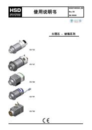
8.1.1 DPC & encoder version<br />
Ref. Description<br />
Power and Thermal switch connector<br />
Data<br />
1 ( 3 Ph + 2 Thermal bimetallic NC 100°C ) L. = 1 m<br />
2 Encoder connector L. = 1 m<br />
3 Coolant inlet 4 l/min min.<br />
4 Coolant outlet 4 l/min min.<br />
5 Toolholder release air inlet 6-7 bar<br />
6 Air inlet for pressurization of spindle 2 bar<br />
7 Air inlet for pressurization of distributor 2 bar<br />
8 DPC water discharge x<br />
9 Internal water inlet / toolholder cleaning 4 bar<br />
10 S1 Drawbar sensor x<br />
11 S2 Tool out sensor x<br />
12 S5 Piston back sensor x<br />
8<br />
8<br />
5<br />
5801H0066 en Rev.01 13/48<br />
11<br />
12<br />
8<br />
8
<strong>HSD</strong><br />
Long nose<br />
Short nose<br />
= =<br />
170<br />
76,5<br />
76,5<br />
170<br />
==<br />
76<br />
76<br />
6<br />
10,5<br />
n°6 fori fissaggio O<br />
n°6 holes<br />
6<br />
10,5<br />
n°6 fori fissaggio O<br />
n°6 holes<br />
430<br />
5801H0066 en Rev.01 14/48<br />
517<br />
3 4<br />
1<br />
3 4<br />
2<br />
1<br />
2<br />
10<br />
7<br />
10<br />
9<br />
7<br />
9
<strong>HSD</strong><br />
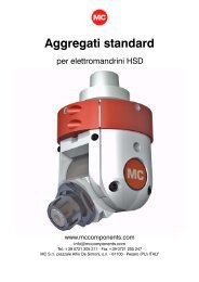
8.1.2 Direct liquid coolant coupling & S3 sensor version<br />
Ref. Description<br />
Power and Thermal switch connector<br />
Data<br />
1 ( 3 Ph + 2 Thermal bimetallic NC 100°C ) L. = 1 m<br />
2 S3 Sensor “shaft idle” L. = 0.1 m<br />
3 Coolant inlet 4 l/min min.<br />
4 Coolant outlet 4 l/min min.<br />
5 Toolholder release air inlet 6-7 bar<br />
6 Air inlet for pressurization of spindle 2 bar<br />
7 Internal water inlet / toolholder cleaning 4 bar<br />
8 S1 Drawbar sensor x<br />
9 S2 Tool out sensor x<br />
10 S5 Piston back sensor x<br />
8<br />
7<br />
5<br />
5801H0066 en Rev.01 15/48<br />
9<br />
10
<strong>HSD</strong><br />
76<br />
76<br />
6<br />
6<br />
n°2 fori per movimentazione M<br />
n°2 handling holes<br />
n°6 fori fissaggio<br />
n°6 holes<br />
O 10.5<br />
3<br />
400<br />
1 2<br />
5801H0066 en Rev.01 16/48<br />
4<br />
Raccordo dritto G 1/8 tubo 8<br />
Straight fitting G 1/8 Ø8
<strong>HSD</strong><br />
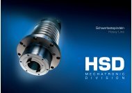
8.1.3 Deublin distributor, encoder & lateral connections<br />
Ref. Description<br />
Power and Thermal switch connector<br />
Data<br />
1 ( 3 Ph + 2 Thermal bimetallic NC 100°C ) L. = 1 m<br />
2 S3 Sensor “shaft idle” L. = 0.1 m<br />
3 Coolant inlet 4 l/min min.<br />
4 Coolant outlet 4 l/min min.<br />
5 Toolholder release air inlet 6-7 bar<br />
6 Air inlet for pressurization of spindle 2 bar<br />
7 Internal water inlet / toolholder cleaning 4 bar<br />
8 S1 Drawbar sensor x<br />
9 S2 Tool out sensor x<br />
10 S5 Piston back sensor x<br />
8<br />
5<br />
5801H0066 en Rev.01 17/48<br />
10<br />
9
<strong>HSD</strong><br />
+0<br />
-0,054<br />
O 105 h8<br />
O 88.5<br />
O 57<br />
76 76<br />
1,6<br />
143.03<br />
128.5<br />
134<br />
0 6 12 93.5<br />
6<br />
137.8<br />
38<br />
9<br />
128.5 218.5 238.5 308.5 317.5 390 415<br />
108.5<br />
415<br />
333.5 369 406<br />
236.8<br />
131.5 100 72<br />
Avanzamento del Deublin in fase di espulsione<br />
Deublin movement during tool holder ejection<br />
5801H0066 en Rev.01 18/48<br />
3<br />
N°6 FORI PER FISSAGGIO<br />
N°6 HOLES<br />
172 70<br />
O 10.5<br />
1<br />
4<br />
2<br />
Deublin 1116-555-463<br />
(NOT INCLUDED)<br />
104<br />
O<br />
N°6 M 6<br />
DEPTH 10 mm<br />
132<br />
6
<strong>HSD</strong><br />
§ 9 INSTALLAZIONE<br />
<strong>HSD</strong> S.p.a. does not and cannot know the methods adopted by the user to install<br />
the spindles. It is therefore the responsibility of the installer or end user to carry<br />
out a risk analysis for each specific installation type and the methods adopted.<br />
It is furthermore the responsibility of the installer to ensure that there is sufficient<br />
protection against accidental contact with moving parts.<br />
The installer and user must also take all the necessary precautions to prevent<br />
other types of risk, particularly those deriving from foreign bodies entering the<br />
equipment, contact with explosive, flammable, toxic or high temperature gases.<br />
Risks relating to maintenance operations must also be taken into consideration.<br />
Maintenance must be performed in conditions of maximum safety, with<br />
electrospindle power switched off and with no risk of tool movement.<br />
9.1 UTILITY SUPPLIES IN THE FACTORY<br />
All preparation work for installation of the electrospindle is the responsibility of the Customer (e.g.<br />
the provision of electricity and compressed air lines, etc.).<br />
The electrical power line to the electrospindle must have sufficient capacity. Connection to the<br />
supply network must be performed by qualified electricians. The Customer is responsible for the<br />
entire electrical supply as far as the electrospindle connectors.<br />
The Customer's attention is drawn to the need to ensure that all safety aspects relating to the<br />
grounding of the electrospindle are complied with.<br />
The ground system must furthermore comply with the standards applicable in the country or state<br />
of installation and must be checked regularly by qualified electricians.<br />
9.2 FIXING<br />
(See figures of chapter § 8)<br />
To fix the electrospindle directly onto the machinery use n°8 M8 stainless steel screws.<br />
To fix an electrospindle equipped with the fixing support use n°8 M10 stainless steel screws and<br />
n°2 reference pins.<br />
9.3 HYDRAULIC CONNECTIONS<br />
See the figures in chapter § 8 for the location and sizes of connections.<br />
See the following sections of this chapter for fluid specifications.<br />
9.4 MOTOR COOLING<br />
The Customer must provide an adequate cooling circuit, with a housing around the spindle for<br />
coolant circulation.<br />
The designer of the machine on which the electrospindle is installed is also responsible for the<br />
design and implementation of the cooling system. The following table indicates the minimum<br />
values that must be respected:<br />
Minimum flow 5 liters / minute<br />
Cooler set temperature 25±3°C<br />
Max. coolant temperature 40°C<br />
Min. inside diameter of delivery and return lines 10 mm<br />
Use water with 10% ethylene glycol and anti-corrosion additives.<br />
5801H0066 en Rev.01 19/48
<strong>HSD</strong><br />
Ethylene glycol concentrations over 15% may damage the NBR gaskets of the<br />
product.<br />
<strong>HSD</strong> recommends the use of ‘ARTIC-FLU-5’ (order code: H2161H0022) after testing it internally.<br />
ARTIC-FLU-5 is a premixed ready-to-use liquid coolant. The coolant contains monoethylene glycol<br />
and ecologically formulated corrosion inhibitors without amines, nitrates or phosphates and<br />
guarantees protection for approximately one year. ARTIC-FLU-5 prevents the formation of rust,<br />
limescale and foam deposits as well as the hardening, cracking and swelling of the rubbers and<br />
couplings. It also complies with various international standards, including CUNA NC 956-16.<br />
9.5 INTERNAL TOOL COOLING<br />
9.5.1 Direct coupling<br />
In the back of the electrospindle is positioned a direct connection of the tool liquid coolant (see<br />
chapter § 8 ).<br />
9.5.2 Deublin distributor<br />
The electrospindle is prepared for the installation of the Deublin distributor.<br />
i<br />
See the use and maintenance manual of the Deublin distributor for the installation of the<br />
component.<br />
9.5.3 Controlled loss water distributor (DPC)<br />
The cooling water reaches the tool through a controlled loss water distributor called “DPC” (<strong>HSD</strong><br />
patented). The exceeding water is drained out of the DPC. Drainage varies according to the water<br />
flow through the tool: the less water comes out through the tool, the more water is drained out of<br />
the DPC.<br />
Drained water comes out from the DPC by gravity, so it’s important to follow the instruction above<br />
to have a correct and complete drainage:<br />
For the correct functioning of the DPC and to avoid damages to the<br />
electrospindle observe the following indications.<br />
� For the internal tool cooling use tap water, or water of equal<br />
characteristics.<br />
� Process the cooling water by a 25 µm filter. Service regularly the filter,<br />
as instructed by the manufacturer, and replace it as it loses its filtering<br />
capability.<br />
� Feed the DPC by a flow of water of 10 liter/minute (0,35 CFM).<br />
� Ensure that the drain holes (see chapter § 8 ) of the controlled loss<br />
distributor are always free to drain.<br />
� In case any tube is connected to the DPC draining holes, it must be<br />
downward oriented. Tubes must remain downward oriented even when<br />
the machine moves the electrospindle (see following figure).<br />
� Tilt the electrospindle only in direction of the draining holes. (see<br />
following figure).<br />
5801H0066 en Rev.01 20/48
<strong>HSD</strong><br />
DPC<br />
5801H0066 en Rev.01 21/48<br />
!
<strong>HSD</strong><br />
9.6 EXTERNAL TOOL COOLING<br />
For the external tool cooling use water with the following specifications:<br />
� Index of aggressiveness (I.A) = 11-12<br />
� Electrical conductivity: not more than 600 microS/cm<br />
� Turbidity not above 20 mg/l<br />
� Chlorides not above 300 mg/l<br />
i<br />
Only an accurate analysis will tell if the water used for the machining process has the<br />
required physical characteristics.<br />
Do not use products containing sodium chloride (NaCl), which cause corrosion<br />
(rust).<br />
When using the <strong>HSD</strong> “Water flange” optional part, do not use de-scaling products<br />
in the external tool cooling circuit. De-scaling products will damage the watertightness<br />
of the “Water flange” unit.<br />
Never direct liquid or air jets to<br />
the pressurized labyrinth seal,<br />
because infiltrations damage the<br />
internal parts of the spindle.<br />
Do not direct liquid or air jets<br />
into the electrospindle when the<br />
tool-holder is not clamped in, as<br />
they could dirt the coupling<br />
surface of the taper fit or they<br />
could get dirt into the<br />
electrospindle.<br />
1 Coupling surface.<br />
2 Labyrinth seal.<br />
1 2<br />
5801H0066 en Rev.01 22/48
<strong>HSD</strong><br />
9.7 COMPRESSED AIR SPECIFICATIONS<br />
Introduce compressed air of a purity in accordance with ISO<br />
IMPORTANT: 8573-1, classes 2 4 3, i.e.:<br />
� class 2 for the solid particles: size of the solid particles < 1 µm<br />
� class 4 for the humidity: dew-point < 3°C (37.4°F)<br />
� class 3 for the total oil: concentration of oil < 1 mg / m 3<br />
Missing to follow the above mentioned specification might cause damage to the product.<br />
Warranty is denied if pollutant traces are found during servicing.<br />
As an example, a possible implementation of the above mentioned specification could be<br />
i made by the following instructions.<br />
� Use nonreturn valve to separate the circuit of the dry air from the circuit of the lubricate<br />
air (if present).<br />
� Install the filters shown in the figure below as near as possible to the electrospindle.<br />
� As filter efficiency is less than 100%, it’s important to feed the compressed air circuit of<br />
the CNC machinery with air properly processed.<br />
As an example, put in point (1) of figure below air of a purity in accordance with ISO<br />
8573-1, classes 7 6 4, i.e.:<br />
o Class 7 for the solid particles:<br />
size of the solid particles < 40 µm;<br />
concentration of solid particles < 10mg/m 3 ;<br />
o Class 6 for the humidity:<br />
dew-point < 10°C;<br />
o Class 4 for the total oil:<br />
concentration of oil < 5 mg/m 3 .<br />
� At the end of the working day, unload the pneumatic circuit, to let the automatic<br />
discharge of the liquids accumulated in the filter cups.<br />
� Service regularly the filters, as instructed by the manufacturers, and replace them as<br />
they lose their filtering capabilities (at least once or twice a year).<br />
1 From compressed air circuit.<br />
2 Pre-filter 5 µm.<br />
3 Anti-oil filter 0,1 µm.<br />
4 To the electrospindle.<br />
1 4<br />
2<br />
5801H0066 en Rev.01 23/48<br />
3
<strong>HSD</strong><br />
9.8 PNEUMATIC CONNECTIONS<br />
i<br />
See the figures in paragraph 8.1 for the location and sizes of connections.<br />
See paragraph 7.1 for air consumptions.<br />
9.9 EXAMPLE OF COMPRESSED AIR CIRCUITS<br />
9.9.1 Tool-holder changing circuit<br />
electrospindle<br />
cilinder<br />
( S )<br />
( R )<br />
5-2 monostable valve<br />
The cylinder of this electrospindle is single-acting.<br />
4<br />
2<br />
1 5<br />
3<br />
hoses : Ø 8x6 Minimum<br />
two step air-cleaning kit<br />
step 1 : 5 μm filter<br />
step 2 : 0,1 μm oil remover<br />
If not supplied is advisable to insert a security valve with open at 2.5/3 Bar<br />
between the cylinder and 5-2 monostable valve.<br />
9.9.2 Pressurization circuit<br />
pressione 4 Bar<br />
pressure<br />
regulator<br />
hoses : Ø 6x4 Minimum<br />
( P )<br />
6 Bar<br />
Pressurization inlet<br />
pressure switch<br />
4 Bar<br />
two step air-cleaning kit<br />
step 1 : 5 μm filter<br />
step 2 : 0,1 μm oil remover<br />
The internal pressurisation pneumatic circuit prevents harmful particles from entering the<br />
electrospindle.<br />
5801H0066 en Rev.01 24/48<br />
6 Bar<br />
The pressurisation air must be present even when the electrospindle is at a<br />
standstill and the machine is switched on. It must be present also when cleaning<br />
or servicing the machinery, to prevent dust from other machining areas entering<br />
the spindle.<br />
Check with the spindle at standstill that there is a uniform outlet of air around the spindle shaft<br />
(pressurisation); if this is not the case, check the efficiency of the pneumatic circuit and the<br />
tightness of the connections.
<strong>HSD</strong><br />
9.10 AUTOMATIC CONE CLEANING<br />
1. 6 bar air inlet<br />
1 2. water inlet for internal tool cooling<br />
3. to be connected to the “water to the tool” inlet (see paragraph 8.1 )<br />
( T )<br />
3<br />
2<br />
Figure aside shows an example of a compressed air circuit for automatic<br />
cone cleaning. During the tool change phase, water delivery is stopped<br />
and compressed air is delivered instead to blow out any dirt which may<br />
have built up. (NOTE: The cone must still be checked and cleaned on a<br />
regular basis as instructed in section § 11 on spindle maintenance).<br />
5801H0066 en Rev.01 25/48
<strong>HSD</strong><br />
9.11 ELECTRICAL CONNECTORS<br />
See the figures in chapter § 8 for the location of connections.<br />
D<br />
C<br />
E<br />
F<br />
A<br />
B<br />
Power connector<br />
(optional)<br />
A Motor phase “U”<br />
B Motor phase “V”<br />
C Motor phase “W”<br />
D Ground PE<br />
E Thermal switch for motor protection (*)<br />
F Thermal switch for motor protection (*)<br />
(*) E and F are the two terminals of a normally<br />
closed (ON) switch, which opens when the motor<br />
reaches a dangerous temperature.<br />
Sensor wiring<br />
1<br />
4 1 +Vcc<br />
3 3 0 V<br />
4 Output<br />
100<br />
5801H0066 en Rev.01 26/48<br />
G<br />
H A<br />
F<br />
K J<br />
E<br />
B<br />
D<br />
C<br />
Encoder connector<br />
(optional)<br />
A A +<br />
B A –<br />
C B –<br />
D GND<br />
E Z +<br />
F +Vcc 12 V DC ÷ 24 V DC �10%<br />
G Not used<br />
H Not used<br />
J B +<br />
K Z –<br />
Cable length : 1m<br />
Proximity sensor assembly<br />
PNP N.O.<br />
with M8 three-pin plug<br />
for sensor: S2, S3 (optional),<br />
S5<br />
Proximity sensor assembly<br />
PNP N.C.<br />
with M8 three-pin plug<br />
for sensor: S1
<strong>HSD</strong><br />
§ 10 OPERATION<br />
10.1 GENERAL PRECAUTIONS<br />
<strong>HSD</strong> S.p.A. has inspected and checked its electrospindles under the standard ambient conditions<br />
(CEI EN 60034-1:2006-05).<br />
Contact <strong>HSD</strong> S.p.A. for information on the possibility of applications in special ambient conditions.<br />
When machining, never allow non-cutting rotating parts (spindle shaft, toolholder etc.) to come into<br />
contact with the piece being machined.<br />
Accidental contact of this sort leads to a risk of serious damage to the electrospindle and injury to<br />
the operator.<br />
10.2 RUNNING IN<br />
The electrospindle is supplied already run-in and ready for installation. The factory running-in cycle<br />
includes careful testing of all controls and signals in simulated work cycles.<br />
10.3 WARMING UP<br />
When you power up the machine at the beginning of each day, allow the electrospindle to warm up<br />
slowly, to allow the bearings to reach a uniform operating temperature with consequent uniform<br />
expansion of the raceways.<br />
To warm up, run the spindle at the following speeds for the times specified:<br />
50% of max rated speed for 2 min.<br />
75% of max rated speed for 2 min.<br />
100% of max rated speed for 1 min.<br />
Repeat this cycle every time the machine is switched off for any length of time, to bring the<br />
electrospindle back up to operating temperature gradually and uniformly.<br />
While the machine operating, the spindle can reach high temperatures.<br />
Be very careful not to touch it without due precautions.<br />
i Preheating is carried out without tool holder.<br />
10.4 TOOL LOCKING AND RELEASE<br />
The tool is mechanically locked by springs.<br />
The tool is released by means of a single acting piston actuated by compressed air at 6 bar.<br />
ELECTROSPINDLE MODEL AXIAL FORCE OF SPRINGS AXIAL FORCE ON TOOL<br />
HOLDER<br />
ISO 40 / ISO 40 Special 4000 N +/- 10% 4000 N +/- 10%<br />
To prevent the toolholder from sticking, remove it after machining.<br />
Always protect the internal parts of the spindle:<br />
lock in a clean and ambient-temperature toolholder when the spindle is not<br />
machining.<br />
5801H0066 en Rev.01 27/48
<strong>HSD</strong><br />
The axial force exerted on the tool holder by the locking system is guaranteed<br />
to be constant for a minimum of 2,000,000 tool changing cycles<br />
1 Tool Changing Cycle = Tool Locked / Tool Released / Tool Locked<br />
All <strong>HSD</strong> electrospindles have a mechanical reactionm system that neutralises the<br />
axial force of the piston on the shaft during the tool changing phase, thus<br />
guaranteeing the integrity of the precision bearings.<br />
10.5 AUTOMATIC CLEANING OF THE SPINDLE SHAFT CONE HOUSING<br />
The tapered housing of the spindle shaft must always be kept perfectly clean and free from dust,<br />
grease, coolant, oil, metal particles, corrosion and scaling.<br />
The compressed air system shown in section 9.10 automatically cleans the cone during tool<br />
changes. This cleaning is not sufficient on its own, however. Regular cleaning must be performed<br />
as instructed in chapter § 11 on maintenance.<br />
10.6 PRESSURISING<br />
Compressed air must be ISO 8573-1, classes 2 4 3 compliant ( see section 9.7 )<br />
There are two pressurizing circuits inside the electrospindle. The purpose of these is to prevent dirt<br />
from entering. Compressed air is distributed to two separate areas:<br />
1. Front mechanical labyrinth: Compressed air is forced out through the ports in the spindle<br />
nose area.<br />
2. Tool cooling water distributor: Compressed air prevents water from entering the draw bar<br />
and release cylinder area. Any water which does get through is drained out through drain holes<br />
provided for the purpose.<br />
10.7 PROXIMITY SENSORS<br />
The electrospindle is fitted with three normally open (NO) and one normally closed (NC) PNP<br />
proximity sensors:<br />
� S1 : DRAW BAR SENSOR (TOOLHOLDER LOCKED)<br />
� S2 : FORWARD PISTON SENSOR (TOOLHOLDER U<strong>NL</strong>OCKED)<br />
� S3 (optional): SHAFT IDLE SENSOR<br />
� S5 : BACKWARD PISTON SENSOR (PISTON IN SAFE CONDITION, AWAY FROM<br />
ROTATING PARTS)<br />
10.7.1 Specifications of proximity sensors<br />
Supply voltage 10 � 30 V (DC)<br />
Maximum load 200 mA<br />
Current absorbed without load � 10 mA<br />
Nominal reading distance 0,8 mm<br />
i<br />
The “ON” condition of the sensor corresponds to the output equal to the supply voltage;<br />
the “OFF” condition corresponds to an output of 0V.<br />
5801H0066 en Rev.01 28/48
<strong>HSD</strong><br />
10.7.2 Electrospindle states and corresponding sensor S1, S2, S5 outputs<br />
STATE S1 S2 S5<br />
Toolholder unlocked, collet open OFF ON OFF<br />
Collet closed without toolholder OFF OFF ON<br />
Tool-holder locked<br />
and piston in safe position<br />
ON OFF ON<br />
The shaft of the electrospindle can only be rotated when the state is “Tool-holder<br />
locked and piston in safe position”; if the outputs of S1 or S5 move to “OFF”, stop<br />
the rotation of the shaft of the electrospindle.<br />
10.7.3 S3 sensor “shaft idle” (optional)<br />
Sensor S3 supplies two “ON” pulses and two “OFF” pulses at each rotation of the shaft, as shown<br />
in the figure below.<br />
0<br />
Image 10-1 output S3 sensor<br />
+ 24 V<br />
For the electrical specifications see section 10.7.1 .<br />
For the installation follow paragraph 12.1 and make sure to obtain the output illustrated in the<br />
Image 10-1.<br />
10.8 THERMAL ALARM<br />
A normally closed switch is installed inside the motor. The switch opens if the motor reaches a<br />
temperature likely to cause damage. Monitor the state of this switch via the wiring described in<br />
section 9.11 and stop the electrospindle if the switch opens (OFF).<br />
If the shaft stops while the tool is being pressed against the workpiece, this may<br />
damage the spindle bearings. If an excessive amount of time is taken to move the<br />
tool away from the workpiece and stop the rotation, there is a risk of burning-out<br />
the stator.<br />
5801H0066 en Rev.01 29/48<br />
1<br />
0 V<br />
giri<br />
rev
<strong>HSD</strong><br />
10.9 ENCODER (OPTIONAL)<br />
The encoder provides information on spindle angle, rotation speed, and rotation direction.<br />
10.9.1 Standard <strong>HSD</strong> TTL rectangular encoder<br />
SPECIFICATION VALUE<br />
Rated feed power: 12 V DC ÷ 24 V DC �10%<br />
Consumption:<br />
Operating<br />
temperature<br />
Max. operating<br />
altitude:<br />
Signal input:<br />
Signal output:<br />
99 mA con 12 V DC<br />
51 mA con 24 V DC<br />
0° C ÷ 70° C<br />
(32° F ÷ 158° F)<br />
2000 m (6500ft)<br />
654 pulses per revolution<br />
and zero signal<br />
TTL compatible electrical<br />
levels<br />
(0V, +5V line driver)<br />
5801H0066 en Rev.01 30/48<br />
A<br />
B<br />
A<br />
B<br />
Z<br />
Z<br />
D<br />
T<br />
5 V<br />
0 V<br />
5 V<br />
0 V<br />
5 V<br />
0 V<br />
5 V<br />
0 V<br />
5 V<br />
0 V<br />
5 V<br />
0 V
<strong>HSD</strong><br />
10.10 CHOICE OF TOOLHOLDER CONE<br />
� The geometry of the ISO conicity must conform to DIN69871 standard (see Image 10-2),<br />
for the special version follow the product specifications (see Image 10-3);<br />
� Avoid the presence of plugs, slots, or other forms affecting the dynamic balancing of the<br />
tool holder<br />
� The degree of dynamic balancing must be G = 2.5 or better (standard ISO1940);<br />
� Balancing is performed with the tool holder assembled (cone, mill collet, ring nut, tool).<br />
63<br />
O<br />
12<br />
O<br />
CONO/CONE ISO 40<br />
ISO/DIS 7388/1<br />
DIN 69871<br />
30°<br />
O 6.35<br />
Image 10-2 – ISO 40 Standard<br />
49.3<br />
35<br />
M 16<br />
15°<br />
O 6.35<br />
Image 10-3 – ISO 40 Special<br />
Codolo/Pull Stud<br />
standard <strong>HSD</strong><br />
code: H080706700<br />
The pull stud (also referred to as retention knob) must be <strong>HSD</strong> article code<br />
H080706700.<br />
It is strictly forbidden to install pull studs of any type other than the <strong>HSD</strong> typeapproved<br />
article specified above. Failure to comply can lead to breakage or<br />
ineffective locking of the toolholder and EXTREMELY SERIOUS RISKS FOR<br />
THE OPERATOR.<br />
When cleaning the cone, make sure that the pull stud is screwed firmly into<br />
the toolholder.<br />
5801H0066 en Rev.01 31/48<br />
61<br />
44<br />
O<br />
Codolo/Pull Stud<br />
standard <strong>HSD</strong><br />
code: H080706700
<strong>HSD</strong><br />
10.11 CHOICE OF TOOL<br />
The following requirements must be respected when choosing a tool:<br />
1. Only use perfectly sharp tools. Make sure that they are locked firmly in the toolholder.<br />
2. Never use bent, damaged, incomplete, or imperfectly balanced tools.<br />
3. Always make sure that the surfaces of the tool are clean and undamaged before fitting it in the<br />
collet.<br />
Never operate tools beyond the rated speed punched on them or that<br />
specified by the manufacturer.<br />
10.12 WHAT TO DO IF THE TOOL IS BLOCKED ON THE PIECE BEING WORKED<br />
In the models with an ISO type tool hooking, if the machine goes into emergency<br />
mode or stops with the tool blocked on the piece being worked, do not move the<br />
spindle along the Z axis!<br />
X<br />
Z<br />
If possible, release the piece manually and then carry out the tool changing manually.<br />
If this is not possible, proceed in the following way:<br />
1. Supply air to the tool changing circuit<br />
2. Slowly move the spindle away from the piece, moving it along the Z axis until the collet<br />
opens (“ON” output of sensor S2)<br />
3. Check the collet spindle has been freed from the collet<br />
4. Move the spindle completely away from the piece being worked<br />
5. Remove the blocked tool manually.<br />
If these procedures are not observed, the tool holder will drag the locking system (collet/tie-rod)<br />
with it until the collet spindle is freed; owing to the force of the spring, the collet will then shoot back<br />
violently, perhaps breaking the tie-rod.<br />
5801H0066 en Rev.01 32/48<br />
Y
<strong>HSD</strong><br />
1 2 3 4<br />
5 6<br />
UTENSILE BLOCCATO<br />
UTENSILE RILASCIATO<br />
IMPATTO<br />
N. Description<br />
1 ISO collet spindle<br />
2 Spindle shaft<br />
3 ISO collet (or bush)<br />
4 Tie-rod<br />
The arrows show the direction in<br />
which the locking system moves<br />
after freeing the collet spindle<br />
Point in which the collet<br />
5<br />
knocks against the shaft<br />
6 Breakage of the tie-rod<br />
5801H0066 en Rev.01 33/48
<strong>HSD</strong><br />
§ 11 ORDINARY MAINTENANCE<br />
i<br />
i<br />
To safely operate an electrospindle installed on the machine, refer to the manual<br />
of the machine itself.<br />
The punctual respect of the scheduled maintenance is essential in order to<br />
maintain the conditions of use and working planned by <strong>HSD</strong> S.p.A. when the<br />
product was put onto the market.<br />
The frequency has been calculated on the basis of a working week of 5 days, each of 8<br />
working hours, under normal environmental working conditions.<br />
Bearings are lubricated for life and do not require further greasing.<br />
Read this section carefully before carrying out any maintenance operation on the electrospindle.<br />
The safety regulations during the maintenance of the electrospindle must take into account that:<br />
� maintenance and/or lubrication operations must only be carried out by trained and qualified<br />
personnel, duly authorised by the technical management of the plant, in accordance with<br />
the safety directives and standards in force, using tools, instruments and products suitable<br />
for this work;<br />
� during maintenance works, it is obligatory to wear suitable clothing, such as close-fitting<br />
overalls, safety shoes, strictly avoiding wide garments or items with protruding parts;<br />
� during maintenance works, we recommend that the machine be cordoned off and the signs<br />
indicating “MACHINE MAINTENANCE” posted.<br />
During any maintenance operations, the electrospindle must be:<br />
� disconnected and isolated from the electric power supply;<br />
� the tool must be strictly at a standstill (not rotating).<br />
The maintenance manager must appoint a team of persons in order to guarantee proper coordination<br />
among the team members and the maximum safety of the persons exposed to danger.<br />
All persons involved in the maintenance operations must be in full visual contact for signalling<br />
possible dangers.<br />
5801H0066 en Rev.01 34/48
<strong>HSD</strong><br />
11.1 DAILY MAINTENANCE<br />
11.1.1 Checking and Cleaning the tool holder seat and the tool holder cone<br />
The contact surfaces between the tool holder and the tool holder seat must be kept clean in order<br />
to guarantee safe hooking.<br />
Image 11-1<br />
1<br />
Image 11-2<br />
Conical surfaces<br />
(in black)<br />
At the start of the work day, check that the surfaces shown in figures are thoroughly clean, with no<br />
traces of dust, grease, cooling liquid, oil, metal particles or machining residues, nor signs of<br />
oxidisation or scale;<br />
if necessary, wipe with a soft, clean cloth.<br />
For cleaning the surfaces indicated, use soft, clean cloths;<br />
NEVER USE abrasive instruments such as wire wool, metal scrapers, emery cloth,<br />
acids or other aggressive elements.<br />
At the end of the working day, clean the surfaces shown in Image 11-1 and Image<br />
11-2 with a soft, clean cloth; inadequate cleaning may result in serious<br />
consequences for the operator's safety, for the wear of the electrospindle and tool<br />
holder, for the precision and efficiency of the machining operation.<br />
Do not direct jets to the area of the<br />
pressurized sealing labyrinth because<br />
infiltrations damage the electrospindles<br />
internal parts.<br />
Do not direct jets inside the electrospindle<br />
when the tool holder is not hooked since the<br />
coupling surface, together with the tool<br />
holder, may get dirty or machining residues<br />
may get into the electrospindle.<br />
1. Coupling surface<br />
2. Labyrinth sealing<br />
1 2<br />
Image 11-3<br />
11.1.2 Protection of the tool holder seat<br />
The tool holder seat must always be protected against the impurities that may come in and could<br />
damage, oxidise or in any other way harm the contact surfaces: never leave the electrospindle<br />
without a tool holder cone inserted.<br />
The cone used for protection must not have through bores.<br />
In order to avoid sticking, remove the tool holder installed on the electrospindle<br />
and replace it with a clean tool holder at room temperature after major machining<br />
operations as well as at the end of the working day, in order to protect the inside<br />
of the electrospindle from the external environment.<br />
The tool holder to be removed may be hot! Use gloves!<br />
5801H0066 en Rev.01 35/48
<strong>HSD</strong><br />
11.2 BIWEEKLY MAINTENANCE<br />
11.2.1 Clean the tool holder cone with ethyl alcohol<br />
Carefully clean the contact surfaces of the tool holders (shown in Image 11-1 and Image 11-2) with<br />
a soft, clean cloth dipped in ethyl alcohol.<br />
5801H0066 en Rev.01 36/48
<strong>HSD</strong><br />
§ 12 REPLACEMENT OF COMPONENTS<br />
Inside the electrospindle, there is a pre-loaded spring with a force of hundreds of<br />
kilograms. This spring is attached to a tie-rod that may be thrown out violently if<br />
the electrospindle is dismantled by personnel who have not been sufficiently<br />
trained.<br />
Carry out only the operations described in this manual, paying close attention to<br />
the instructions given; for further information, contact <strong>HSD</strong> S.p.A. Customer<br />
Service.<br />
Observe the safety precautions for maintenance given on page Errore. Il segnalibro<br />
non è definito..<br />
Only the adjustment and replacement operations with original <strong>HSD</strong> S.p.A. spare<br />
parts described in this section of the manual are permitted.<br />
Any other type of operation is not permitted and will invalidate the product<br />
warranty.<br />
5801H0066 en Rev.01 37/48
<strong>HSD</strong><br />
12.1 REPLACEMENT AND ADJUSTMENT OF THE SENSOR GROUP<br />
For the position of sensors see the paragraph 8.1 .<br />
12.1.1 Description of the sensor unit<br />
The sensors are pre-assembled in calibrated bushes to allow simple insertion to the right depth in<br />
the electrospindle. It is therefore important to correctly identify the sensor to be replaced: for this<br />
reason, both the sensors installed on the electrospindle and those supplied as spare parts bear a<br />
numbered label (Image 12-1).<br />
Confusion of the sensors will result in damage to the moving parts.<br />
1<br />
Image 12-2<br />
Sensor fastening through bracket<br />
Image 12-1<br />
5801H0066 en Rev.01 38/48<br />
9<br />
3<br />
6<br />
8<br />
4<br />
7 2<br />
Ch 12<br />
Image 12-3<br />
Sensor fastening through block<br />
1 Electrical connector 6 Calibrated position<br />
2 Eccentricity marking 7 Bracket or block<br />
3 Bush 8 Sensor unit<br />
4 Sensor 9 Screw<br />
Eccentricity between<br />
5<br />
regulation sensor<br />
bush and<br />
5
<strong>HSD</strong><br />
12.1.2 Replacement and adjustment of the sensor unit<br />
i<br />
For the replacement and adjustment of the sensors shown in this paragraph (and those<br />
to follow), always refer to Image 12-1; Image 12-2; Image 12-3 of the previous<br />
paragraph.<br />
1. Remove screw “9” that blocks the bracket or block “6” of the sensor unit “8” to be replaced;<br />
2. unthread the faulty sensor unit from its seat, and disconnect its electrical connector “1”;<br />
3. connect the electrical connector of the new sensor unit to the correspondingly numbered<br />
connector of the spindle;<br />
4. check the functioning of the new sensor by bringing it into contact with a metallic mass;<br />
5. Insert the new sensor unit in the empty seat;<br />
6. reposition the bracket “7” and lock the screw “9” again without tighten it completely, so that<br />
the sensor unit can rotate;<br />
7. rotate the sensor unit a few degrees at a time, until you obtain the outputs requested in the<br />
paragraphs immediately below;<br />
8. tighten the screw “9” by blocking the sensor unit with an open-end spanner so as to<br />
maintain the calibration carried out.<br />
12.1.3 Sensor S1 adjustment<br />
After replacing the sensor unit as described in section 12.1.2 , adjust it as follows:<br />
1. do not tighten the sensor completely until an accurate adjustment has been performed;<br />
2. attach the tool holder cone and ensure that the output of S1 is “ON”; if the output is “OFF”,<br />
rotate the sensor unit until it becomes “ON”;<br />
3. the sensor “4” is eccentric in relation to the bush “3” that contains it: rotate the bush slowly<br />
in the direction that takes the sensor away from the tool holder;<br />
stop immediately when the output of the sensor becomes ”OFF”;<br />
4. carefully rotate the bush back by about 15° - 20°, so that the output of the sensor returns to<br />
“ON”;<br />
5. rotate the shaft manually, and check that the signal remains “ON” for the whole rotation;<br />
6. tighten fixing screw “9”;<br />
7. release the tool holder by powering the piston at the pressure indicated in the section 8.1<br />
and check that in this condition (collet open) the output of S1 is “OFF”;<br />
8. release the pressure at the piston and allow the collet to close without tool holder: in this<br />
condition, the output of S1 must be “OFF” for the whole rotation of the shaft;<br />
9. if points (7) and (8) are not satisfied repeat the procedure from the start, making an even<br />
slighter rotation movement at point (4);;<br />
10. if points (7) and (8) are satisfied, make a cycle of 10 tool changes;<br />
11. at the end of the cycle, check that the conditions in the following table are satisfied:<br />
CONDIZIONE OUTPUT S1<br />
tool holder locked ON (*)<br />
missing tool holder<br />
with closed collet<br />
collet open<br />
(tool holder ejected) OFF<br />
OFF (*)<br />
(*) for the whole rotation of the shaft<br />
12. if the conditions of the table are not satisfied, repeat the procedure from the beginning;<br />
13. if the conditions of the table are satisfied, perform a cycle of 100 tool changes with the<br />
machine, using the maximum possible number of different tool holders.;<br />
14. At the end of the cycle, check that the conditions in the table under point (11) are satisfied:<br />
if this is the case, the regulation procedure for S1 is complete; if this is not the case,<br />
repeat the procedure from the beginning.<br />
5801H0066 en Rev.01 39/48
<strong>HSD</strong><br />
12.1.4 Sensor S2 adjustment<br />
After replacing the sensor unit as described in section 12.1.2 , adjust it as follows:<br />
1. correctly attach a tool holder before beginning the adjustment of the sensor;<br />
2. check that, in this state, the output of S2 is “OFF”; if the output is “ON”, rotate the sensor<br />
unit until it becomes “OFF”;<br />
3. feed the cylinder by means of a one-way pressure regulator initially set at 0 bar (0 PSI);<br />
4. increase the feed pressure by steps of 0.1 bar (1.5 PSI) so as to move the piston slowly<br />
forward and, at the same time, check that the output of S2 is “OFF”;<br />
5. as long as the tool holder is firmly blocked, the output of S2 must be “OFF”;<br />
if the output changes during the movement of the piston, slightly rotate the sensor unit until<br />
the output returns to “OFF”;<br />
6. when the tool holder begins to slacken (but is not yet free to fall), the output of S2 must still<br />
be “OFF” (if necessary, rotate the sensor unit);<br />
7. when you reach the feed pressure at which the tool holder is finally free to fall, increase the<br />
pressure by another 0.2 bar (3 PSI) and block the pressure regulator;<br />
8. rotate the sensor unit so that, in this state, the output of S2 becomes “ON”;<br />
9. perform a cycle of 10 tool changes;<br />
10. at the end of the cycle, check that the steps from (1) to (8) are satisfied without the need<br />
to ever rotate the sensor;<br />
11. if the outputs requested are not satisfied, repeat the entire procedure from the start;<br />
12. if the outputs requested are satisfied, perform a cycle of 100 tool changes with the<br />
machine, using the maximum possible number of different tool holders;<br />
13. at the end of the cycle, check that the steps from (1) to (8) are satisfied without the need<br />
to ever rotate the sensor;<br />
14. if the outputs requested are not satisfied, repeat the entire procedure from the start;<br />
15. if the outputs requested are satisfied, the regulation procedure for S2 is complete.<br />
5801H0066 en Rev.01 40/48
<strong>HSD</strong><br />
12.1.5 Sensor S5 adjustment<br />
After replacing the sensor unit as described in section 12.1.2 , adjust it as follows:<br />
1. correctly attach a tool holder before beginning the adjustment of the sensor;<br />
2. supply 6 bar (87 PSI) to the cylinder so as to keep the piston at the upper end stop<br />
3. position the sensor at the highest position allowed by movement (step 6 section 12.1.2 )<br />
[“high” = direction opposed to the tool holder];<br />
4. check that, in this condition, the output of S5 is “OFF”;<br />
5. move the sensor downwards in small steps, until you find the position at which the output of<br />
S5 becomes “ON”;<br />
6. slightly move the sensor by another small step downwards;<br />
7. lock the position of the sensor by tightening screw (3);<br />
8. carry out 10 cycles of “tool expulsion” - “return to upper end stop”;<br />
9. bring the piston to the upper end stop;<br />
10. check that, in this condition, the output of S5 is “ON”;<br />
11. free the input of the air to return the piston to the upper end stop in the cylinder;<br />
12. feed the air input for “tool holder ejection” of the cylinder, using a one-way pressure<br />
regulator initially set at 0 bar (0 PSI);<br />
13. increase the feed pressure by 0.1 bar (1.5 PSI) steps and, at the same time, rotate the<br />
shaft manually to check that it rotates freely and is not hampered by dragging against the<br />
piston;<br />
14. when the output of S5 becomes “OFF”, the manual rotation of the shaft must still be<br />
absolutely free;<br />
15. if the cylinder drags against the shaft when sensor S5 is still “ON”, this means that at point<br />
[6] of this procedure, the sensor was advanced too far: repeat the whole procedure, making<br />
much finer movements at point [6];<br />
16. if point [14] of the procedure is satisfied, perform 50 “tool ejection” - “return to upper end<br />
stop” cycles;<br />
17. check the adjustment, repeating steps [9] to [16] of this procedure four times.<br />
5801H0066 en Rev.01 41/48
<strong>HSD</strong><br />
§ 13 DISPOSING OF THE PRODUCT<br />
Observe the safety precautions for maintenance given on page 34 and 37.<br />
At the end of the electrospindle's working life it is the Customer’s responsibility to dispose of it<br />
correctly.<br />
First of all, clean the unit and separate the various components into mechanical and electrical<br />
parts. Then separate the component parts according to type of material: electric motors (copper<br />
windings), metal parts (body, etc.), plastic parts, etc.. Dispose of the various materials in<br />
compliance with the laws and regulations applicable in the country where the electrospindle has<br />
been installed.<br />
5801H0066 en Rev.01 42/48
<strong>HSD</strong><br />
§ 14 LIST OF SPARE PARTS<br />
CODE DESCRIPTION<br />
H5664H0040 Kit S2, S5 inductive sensor<br />
H5664H0062 Kit S1 inductive sensor<br />
H5631H0537 Kit S3 inductive sensor<br />
H6202H0079 Cylinder assembly<br />
FNZ4100033 Motor plate<br />
H2161H0022 Cooling fluid ARTIC-FLU-5 (5-litre canister)<br />
5801H0066 en Rev.01 43/48
<strong>HSD</strong><br />
§ 15 TROUBLESHOOTING<br />
PROBLEMS CAUSES REMEDIES<br />
The electrospindle does<br />
not turn:<br />
There is no power<br />
No tool holder is fitted Fit a tool holder.<br />
The tool holder not correctly<br />
seated<br />
The thermal switch has tripped<br />
The inverter switch has tripped<br />
Sensor S1 or sensor S5 are<br />
disconnected or faulty<br />
� Check the mains power<br />
supply.<br />
� Check all power terminals.<br />
� Check all electrical cables and<br />
connections for breaks.<br />
See “The tool holder is not<br />
locked” below.<br />
Wait for the electrospindle to cool<br />
down and the thermal switch will<br />
automatically reset.<br />
If the thermal switch trips<br />
frequently, see “The<br />
electrospindle overheats” below.<br />
Consult the inverter's own manual<br />
or contact the inverter<br />
manufacturer.<br />
� Check the sensor connectors.<br />
� Check the sensor cables for<br />
breaks.<br />
� Contact the <strong>HSD</strong> technical<br />
assistance service.<br />
5801H0066 en Rev.01 44/48
<strong>HSD</strong><br />
The tool holder is not<br />
locked:<br />
The tool holder is not<br />
ejected:<br />
There is no air pressure<br />
inside the electrospindle:<br />
One of the sensors does<br />
not give the required<br />
output:<br />
There is dirt or foreign bodies<br />
between the tool holder and the<br />
spindle shaft housing<br />
The tool holder cone is not of<br />
the right type<br />
There is insufficient air pressure<br />
to open the collet<br />
Sensor S2 is disconnected or<br />
faulty<br />
There is insufficient air pressure<br />
There is insufficient air pressure<br />
or the compressed air system is<br />
faulty<br />
A sensor is disconnected or<br />
faulty<br />
Remove any large foreign bodies<br />
and clean the tool holder cone<br />
and spindle housing as instructed<br />
in section § 11.<br />
Choose a tool holder as<br />
instructed in section § 10.<br />
� Check the air pressure<br />
settings in accordance with<br />
section 8.1 ;<br />
� Check the compressed air<br />
system for leaks and pressure<br />
losses.<br />
� Check the sensor connectors.<br />
� Check the sensor cables for<br />
breaks.<br />
� Contact the <strong>HSD</strong> technical<br />
assistance service.<br />
� Check the air pressure<br />
settings in accordance with<br />
paragraph 8.1 ;<br />
� Check the compressed air<br />
system for leaks and pressure<br />
losses.<br />
� Check the air pressure<br />
settings in accordance with<br />
sections 8.1 ;<br />
� Check the compressed air<br />
system for leaks and pressure<br />
losses;<br />
� Contact the <strong>HSD</strong> Technical<br />
Assistance Service.<br />
� Check the sensor connectors;<br />
� Check the sensor cables for<br />
breaks;<br />
� Contact the <strong>HSD</strong> technical<br />
assistance service.<br />
5801H0066 en Rev.01 45/48
<strong>HSD</strong><br />
The electrospindle<br />
overheats:<br />
Performance below<br />
specifications:<br />
The electrospindle<br />
vibrates:<br />
The bearings are noisy:<br />
Cooling problems:<br />
The machining is taking up too<br />
much power<br />
The inverter setup is incorrect<br />
The inverter setup is incorrect<br />
The tool holder is not balanced<br />
The tool is not balanced<br />
There is dirt or foreign bodies<br />
between the tool holder and the<br />
spindle shaft housing<br />
The inverter setup is incorrect<br />
The machining is taking up too<br />
much power<br />
� Check cooling circuit<br />
specifications in section 9.4 ;<br />
� Check the cooling system for<br />
leaks and losses or clogging.<br />
� Contact the <strong>HSD</strong> Technical<br />
Assistance Service.<br />
Reduce the machining power<br />
requirements.<br />
Check the specifications of the<br />
electrospindle on its data label<br />
and in paragraph 7.1 .<br />
Check the specifications of the<br />
electrospindle on its data label<br />
and in paragraph 7.1 .<br />
Choose a tool holder in<br />
accordance with paragraph § 10.<br />
Choose a tool in accordance with<br />
paragraph § 10.<br />
Remove any large foreign bodies<br />
and clean the tool holder cone<br />
and spindle housing as instructed<br />
in section § 11.<br />
Check the specifications of the<br />
electrospindle on its data label<br />
and in paragraph 7.1 .<br />
Reduce the machining power<br />
requirements.<br />
The fixing bolts are loose Tighten the fixing bolts.<br />
The bearings are worn or Contact the <strong>HSD</strong> technical<br />
damaged<br />
assistance service.<br />
The bearings are worn or Contact the <strong>HSD</strong> technical<br />
damaged<br />
assistance service.<br />
5801H0066 en Rev.01 46/48
<strong>HSD</strong><br />
§ 16 DECLARATION OF INCORPORATION<br />
Pesaro 29/07/2010<br />
ELECTROSPINDLE<br />
MODEL 794<br />
5801H0066 en Rev.01 47/48
<strong>HSD</strong><br />
<strong>HSD</strong><br />
MECHATRONIC<br />
D I V I S I O N<br />
<strong>HSD</strong> S.p.a.<br />
Registered office:<br />
Via della Meccanica 16<br />
61122 PESARO (ITALIA)<br />
Loc. Chiusa di Ginestreto<br />
Factory headquarters:<br />
P.le A.De Simoni, sn<br />
61122 PESARO (ITALIA)<br />
Tel. +39 0721 205 211<br />
Fax +39 0721 205 247<br />
E-mail supporthsd@hsd.it<br />
web www.hsd.it<br />
<strong>HSD</strong> Deutschland GmbH<br />
Brückenstrasse 32<br />
D-73037 Göppingen (DEUTSCHLAND)<br />
Tel. +49 07161 956 660<br />
Fax +49 07161 956 661 0<br />
E-mail supporthsddeut@hsddeutschland.de<br />
web www.hsddeutschland.de<br />
<strong>HSD</strong> USA Inc.<br />
3764 SW, 30 th Avenue<br />
Hollywood, Florida 33312 USA<br />
Phone no. +1 954 587 1991<br />
Fax +1 954 587 8338<br />
E-mail supporthsdusa@hsd.it<br />
web www.hsdusa.com<br />
<strong>HSD</strong> Mechatronic Shangai Co. Ltd.<br />
D2, First floor, 207 Taigu Road<br />
Waigaoquiao, Free Trade Zone<br />
200131, Shangai - CHINA<br />
Phone no. +86 215 866 1236<br />
E-mail sales@hsd-china.cn<br />
web www.hsd-china.cn<br />
5801H0066 en Rev.01 48/48