ES721 ISO40 7 kW NL - HSD
ES721 ISO40 7 kW NL - HSD
ES721 ISO40 7 kW NL - HSD

Create successful ePaper yourself
Turn your PDF publications into a flip-book with our unique Google optimized e-Paper software.
<strong>HSD</strong><br />
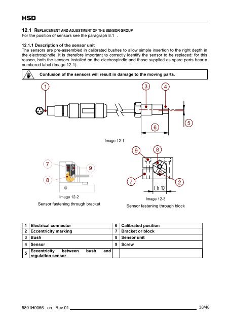
12.1 REPLACEMENT AND ADJUSTMENT OF THE SENSOR GROUP<br />
For the position of sensors see the paragraph 8.1 .<br />
12.1.1 Description of the sensor unit<br />
The sensors are pre-assembled in calibrated bushes to allow simple insertion to the right depth in<br />
the electrospindle. It is therefore important to correctly identify the sensor to be replaced: for this<br />
reason, both the sensors installed on the electrospindle and those supplied as spare parts bear a<br />
numbered label (Image 12-1).<br />
Confusion of the sensors will result in damage to the moving parts.<br />
1<br />
Image 12-2<br />
Sensor fastening through bracket<br />
Image 12-1<br />
5801H0066 en Rev.01 38/48<br />
9<br />
3<br />
6<br />
8<br />
4<br />
7 2<br />
Ch 12<br />
Image 12-3<br />
Sensor fastening through block<br />
1 Electrical connector 6 Calibrated position<br />
2 Eccentricity marking 7 Bracket or block<br />
3 Bush 8 Sensor unit<br />
4 Sensor 9 Screw<br />
Eccentricity between<br />
5<br />
regulation sensor<br />
bush and<br />
5