ES721 ISO40 7 kW NL - HSD
ES721 ISO40 7 kW NL - HSD
ES721 ISO40 7 kW NL - HSD
You also want an ePaper? Increase the reach of your titles
YUMPU automatically turns print PDFs into web optimized ePapers that Google loves.
<strong>HSD</strong><br />
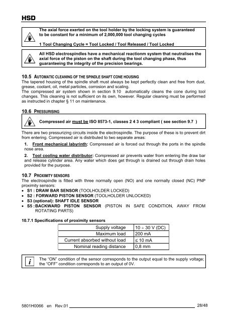
The axial force exerted on the tool holder by the locking system is guaranteed<br />
to be constant for a minimum of 2,000,000 tool changing cycles<br />
1 Tool Changing Cycle = Tool Locked / Tool Released / Tool Locked<br />
All <strong>HSD</strong> electrospindles have a mechanical reactionm system that neutralises the<br />
axial force of the piston on the shaft during the tool changing phase, thus<br />
guaranteeing the integrity of the precision bearings.<br />
10.5 AUTOMATIC CLEANING OF THE SPINDLE SHAFT CONE HOUSING<br />
The tapered housing of the spindle shaft must always be kept perfectly clean and free from dust,<br />
grease, coolant, oil, metal particles, corrosion and scaling.<br />
The compressed air system shown in section 9.10 automatically cleans the cone during tool<br />
changes. This cleaning is not sufficient on its own, however. Regular cleaning must be performed<br />
as instructed in chapter § 11 on maintenance.<br />
10.6 PRESSURISING<br />
Compressed air must be ISO 8573-1, classes 2 4 3 compliant ( see section 9.7 )<br />
There are two pressurizing circuits inside the electrospindle. The purpose of these is to prevent dirt<br />
from entering. Compressed air is distributed to two separate areas:<br />
1. Front mechanical labyrinth: Compressed air is forced out through the ports in the spindle<br />
nose area.<br />
2. Tool cooling water distributor: Compressed air prevents water from entering the draw bar<br />
and release cylinder area. Any water which does get through is drained out through drain holes<br />
provided for the purpose.<br />
10.7 PROXIMITY SENSORS<br />
The electrospindle is fitted with three normally open (NO) and one normally closed (NC) PNP<br />
proximity sensors:<br />
� S1 : DRAW BAR SENSOR (TOOLHOLDER LOCKED)<br />
� S2 : FORWARD PISTON SENSOR (TOOLHOLDER U<strong>NL</strong>OCKED)<br />
� S3 (optional): SHAFT IDLE SENSOR<br />
� S5 : BACKWARD PISTON SENSOR (PISTON IN SAFE CONDITION, AWAY FROM<br />
ROTATING PARTS)<br />
10.7.1 Specifications of proximity sensors<br />
Supply voltage 10 � 30 V (DC)<br />
Maximum load 200 mA<br />
Current absorbed without load � 10 mA<br />
Nominal reading distance 0,8 mm<br />
i<br />
The “ON” condition of the sensor corresponds to the output equal to the supply voltage;<br />
the “OFF” condition corresponds to an output of 0V.<br />
5801H0066 en Rev.01 28/48


