ES721 ISO40 7 kW NL - HSD
ES721 ISO40 7 kW NL - HSD
ES721 ISO40 7 kW NL - HSD

Create successful ePaper yourself
Turn your PDF publications into a flip-book with our unique Google optimized e-Paper software.
<strong>HSD</strong><br />
10.7.2 Electrospindle states and corresponding sensor S1, S2, S5 outputs<br />
STATE S1 S2 S5<br />
Toolholder unlocked, collet open OFF ON OFF<br />
Collet closed without toolholder OFF OFF ON<br />
Tool-holder locked<br />
and piston in safe position<br />
ON OFF ON<br />
The shaft of the electrospindle can only be rotated when the state is “Tool-holder<br />
locked and piston in safe position”; if the outputs of S1 or S5 move to “OFF”, stop<br />
the rotation of the shaft of the electrospindle.<br />
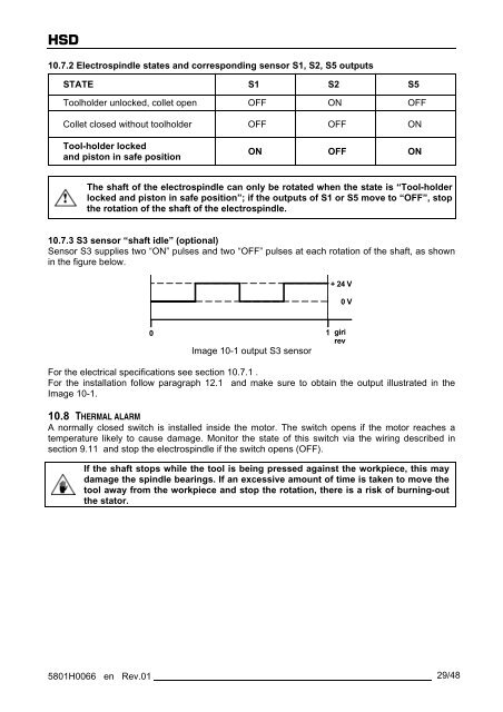
10.7.3 S3 sensor “shaft idle” (optional)<br />
Sensor S3 supplies two “ON” pulses and two “OFF” pulses at each rotation of the shaft, as shown<br />
in the figure below.<br />
0<br />
Image 10-1 output S3 sensor<br />
+ 24 V<br />
For the electrical specifications see section 10.7.1 .<br />
For the installation follow paragraph 12.1 and make sure to obtain the output illustrated in the<br />
Image 10-1.<br />
10.8 THERMAL ALARM<br />
A normally closed switch is installed inside the motor. The switch opens if the motor reaches a<br />
temperature likely to cause damage. Monitor the state of this switch via the wiring described in<br />
section 9.11 and stop the electrospindle if the switch opens (OFF).<br />
If the shaft stops while the tool is being pressed against the workpiece, this may<br />
damage the spindle bearings. If an excessive amount of time is taken to move the<br />
tool away from the workpiece and stop the rotation, there is a risk of burning-out<br />
the stator.<br />
5801H0066 en Rev.01 29/48<br />
1<br />
0 V<br />
giri<br />
rev