RE10TC Temperature Control Module Operating manual
RE10TC Temperature Control Module Operating manual
RE10TC Temperature Control Module Operating manual

Create successful ePaper yourself
Turn your PDF publications into a flip-book with our unique Google optimized e-Paper software.
PID control Functions<br />
There can be simultaneously multiple messages.<br />
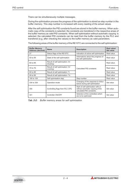
During the optimisation process the progress of the optimisation is stored as step number in the<br />
buffer memory. This step number is increased with every reading of the actual values.<br />
After the self optimisation the PID constants found are stored in the buffer memory. When automatic<br />
copy of the constants is selected, the constants are transfered in the respective areas of<br />
the buffer memory as valid PID constants. When self optimisation without automatic copying is<br />
selected, the calculated PID constants can be read from the buffer memory by the PLC and<br />
transfered (e.g. after checking the values) to the buffer memory as valid parameters.<br />
The following areas of the buffer memory of the <strong>RE10TC</strong> are connected to the self optimisation:<br />
Buffer Memory<br />
Address (decimal)<br />
Name Description<br />
Real value/<br />
Set value<br />
27 Status flags of the <strong>RE10TC</strong> Indication of active self optimisation Real value<br />
50 to 59 State of the self optimisation<br />
Informations about the progress of<br />
the self optimisation<br />
Real value<br />
60 to 69<br />
Result of self optimisation: XP<br />
(heating)<br />
Real value<br />
70 to 79<br />
Result of self optimisation: XP<br />
(cooling)<br />
Calculated PID constants<br />
Real value<br />
80 to 89 Result of self optimisation: TI Real value<br />
90 to 99 Result of self optimisation: TD Real value<br />
100 to 109 Self optimisation step Step number Real value<br />
330 to 339 Operation mode<br />
340 <strong>Control</strong>ling flags from PLC CPU<br />
341 <strong>Control</strong>ler ON/OFF<br />
Tab. 2-2: Buffer memory areas for self optimisation<br />
Changing of the response to disturbance<br />
during self optimisation<br />
Start of self optimisation with or<br />
without automatic copying of the<br />
calculated PID constants<br />
Selection of the controllers which<br />
are to be optimized<br />
Set value<br />
Set value<br />
Set value<br />
2-4 MITSUBISHI ELECTRIC