RE10TC Temperature Control Module Operating manual
RE10TC Temperature Control Module Operating manual
RE10TC Temperature Control Module Operating manual

Create successful ePaper yourself
Turn your PDF publications into a flip-book with our unique Google optimized e-Paper software.
Functions Measuring of temperatures<br />
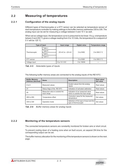
2.2 Measuring of temperatures<br />
2.2.1 Configuration of the analog inputs<br />
Different types of thermocouples or a KTY sensor can be selected as temperature sensor of<br />
each temperature controller by making settings in the buffer memory addresses 330 to 339. The<br />
analog input can be set for measuring a voltage between 0 and 10 V as well.<br />
When set as voltage input, the temperature curve is presumed to be linear. If e.g. a temperature<br />
betwen 0 and 250 �C gives a voltage reading from 0 to 10 Volts, the temperature for a setpoint of<br />
5 V will be 125 �C.<br />
Type of input Input range Digital value <strong>Temperature</strong> range<br />
Type J<br />
Type K<br />
Thermocouple<br />
Type L<br />
Type U<br />
�30 mV to �30 mV 0 to 5000 0 to 500.0 �C<br />
KTY sensor 0 to 5000 0 to 500.0 �C<br />
Voltage input 0 to 10 V DC 0 to 10000 —<br />
Tab. 2-3: Selectable types of inputs<br />
The following buffer memory areas are connected to the analog inputs of the <strong>RE10TC</strong>:<br />
Buffer Memory<br />
Address (decimal)<br />
Name Description<br />
2.2.2 Monitoring of the temperature sensors<br />
The connected temperature sensors are constantly monitored for broken wire or short circuit.<br />
To prevent cooling down of a heating zone when an fault occurs, an separat ON time for the<br />
corresponding output can be set.<br />
The buffer memory allocation for the monitoring of the temperature sensors is shown on the next<br />
page:<br />
MITSUBISHI ELECTRIC 2 - 5<br />
Real value/<br />
Set value<br />
0 to 9 Measured values<br />
Scaled values from the analog<br />
inputs<br />
Real values<br />
27 Status flags of the <strong>RE10TC</strong> Indication of activated calibration Real values<br />
45<br />
Measured value is outside the<br />
input range<br />
260 to 269 <strong>Temperature</strong> offset<br />
330 to 339 Operation mode<br />
Tab. 2-4: Buffer memory areas for analog inputs<br />
Indication of an measured value<br />
which is outside the input range<br />
Correction value for the measured<br />
temperature<br />
Selection of the type of input and the<br />
type of thermocouple<br />
Real values<br />
Set values<br />
Set values