RE10TC Temperature Control Module Operating manual
RE10TC Temperature Control Module Operating manual
RE10TC Temperature Control Module Operating manual

Create successful ePaper yourself
Turn your PDF publications into a flip-book with our unique Google optimized e-Paper software.
Buffer Memory Details of the set values<br />
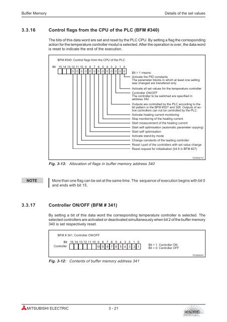
3.3.16 <strong>Control</strong> flags from the CPU of the PLC (BFM #340)<br />
The bits of this data word are set and reset by the PLC CPU. By setting a flag the corresponding<br />
action for the temperature controller modul is selected. After the operation is over, the data word<br />
is reset to indicate the end of the execution.<br />
BFM #340: <strong>Control</strong> flags from the CPU of the PLC<br />
Bit 15 14 13 12 11 10 9 8 7 6 5 4 3 2 1 0<br />
NOTE More than one flag can be set at the same time. The sequence of execution begins with bit 0<br />
and ends with bit 15.<br />
3.3.17 <strong>Control</strong>ler ON/OFF (BFM # 341)<br />
0<br />
By setting a bit of this data word the corresponding temperature controller is selected. The<br />
selected controllers are activated or deactivated simultaneously when bit 2 of the buffer memory<br />
340 is set respectively reset.<br />
BFM # 341: <strong>Control</strong>ler ON/OFF<br />
Bit 15 14 13 12 11 10 9 8 7 6 5 4 3 2 1 0<br />
<strong>Control</strong>ler<br />
10 9 8 7 6 5 4 3 2 1<br />
Fig. 3-12: Contents of buffer memory address 341<br />
MITSUBISHI ELECTRIC 3 - 21<br />
0<br />
0 0 0 0 0 0 0 0 0<br />
Fig. 3-13: Allocation of flags in buffer memory address 340<br />
0<br />
0<br />
Bit = 1 means:<br />
Activate the PID constants<br />
The parameter blocks in which at least one setting<br />
was changed are transfered only.<br />
Activate all set values for the temperature controller<br />
<strong>Control</strong>ler ON/OFF<br />
The controller to be switched are specified in<br />
address 342.<br />
Outputs are controlled by the PLC according to the<br />
bit pattern in the BFM #327 and 328. Outputs of active<br />
controllers can not be controlled by the PLC.<br />
Activate heating current monitoring<br />
Stop monitoring of the heating current<br />
Start measurement of the heating current<br />
Start self optimisation (automatic parameter copying)<br />
Start self optimisation<br />
Activate stand-by mode<br />
Change constants of the leading controller<br />
Reset I-part of the controllers with set value change<br />
Reset request for initialisation (bit 8 in BFM #27)<br />
Bit = 1: <strong>Control</strong>ler ON<br />
Bit = 0: <strong>Control</strong>ler OFF<br />
TC00021C<br />
TC00022C