RE10TC Temperature Control Module Operating manual
RE10TC Temperature Control Module Operating manual
RE10TC Temperature Control Module Operating manual

Create successful ePaper yourself
Turn your PDF publications into a flip-book with our unique Google optimized e-Paper software.
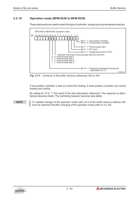
Details of the set values Buffer Memory<br />
3.3.15 Operation mode (BFM #330 to BFM #339)<br />
These data words are used to select the type of controller, analog input and temperature sensor.<br />
BFM #330 to BFM #339: Operation mode<br />
Bit 15 14 13 12 11 10 9 8 7 6 5 4 3 2 1 0<br />
0 0 0 0 0<br />
Fig. 3-11: Contents of the buffer memory addresses 330 to 339<br />
A two-position controller is able to control the heating. A three-position controller can control<br />
heating and cooling.<br />
By setting bit 10 to “1” the result of the self optimisation influenced. The response to disturbances<br />
becomes faster. The controlling however becomes less stable.<br />
NOTE To validate changes of the operation mode valid, bit 0 of the buffer memory address 340<br />
must be switched ON after changing of the operation mode (refer to 3.3.16).<br />
0<br />
0<br />
Bit 0 = 1: Two-position controller<br />
Bit 0 = 0: Three-position controller<br />
Bit 1 = 1: Thermocouple input<br />
Bit 2 = 1: KTY input<br />
Bit 3 = 1: Voltage input (0 to10 V DC)<br />
Selection of the type of thermocouple with bit 8 and bit 9:<br />
0 0: Thermocouple type L<br />
0 1: Thermocouple type J<br />
1 0: Thermocouple type K<br />
1 1: Thermocouple type U<br />
Bit 10 = 1: Response enlargement during self<br />
optimisation by 1.2<br />
TC00020C<br />
3-20 MITSUBISHI ELECTRIC