RE10TC Temperature Control Module Operating manual
RE10TC Temperature Control Module Operating manual
RE10TC Temperature Control Module Operating manual
You also want an ePaper? Increase the reach of your titles
YUMPU automatically turns print PDFs into web optimized ePapers that Google loves.
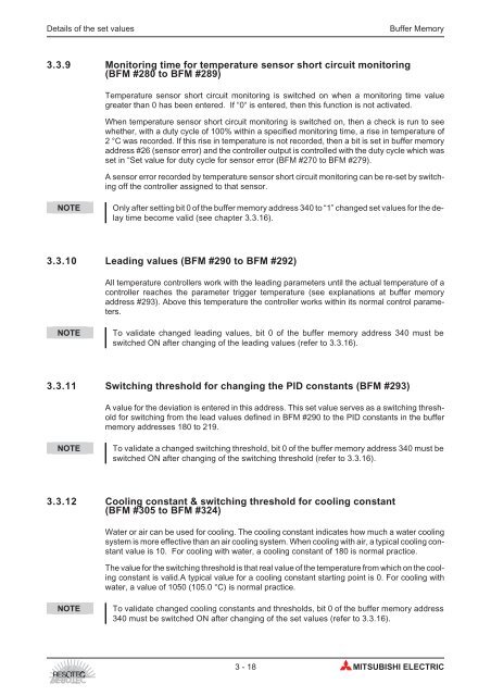
Details of the set values Buffer Memory<br />
3.3.9 Monitoring time for temperature sensor short circuit monitoring<br />
(BFM #280 to BFM #289)<br />
<strong>Temperature</strong> sensor short circuit monitoring is switched on when a monitoring time value<br />
greater than 0 has been entered. If “0“ is entered, then this function is not activated.<br />
When temperature sensor short circuit monitoring is switched on, then a check is run to see<br />
whether, with a duty cycle of 100% within a specified monitoring time, a rise in temperature of<br />
2 °C was recorded. If this rise in temperature is not recorded, then a bit is set in buffer memory<br />
address #26 (sensor error) and the controller output is controlled with the duty cycle which was<br />
set in “Set value for duty cycle for sensor error (BFM #270 to BFM #279).<br />
A sensor error recorded by temperature sensor short circuit monitoring can be re-set by switching<br />
off the controller assigned to that sensor.<br />
NOTE Only after setting bit 0 of the buffer memory address 340 to “1” changed set values for the delay<br />
time become valid (see chapter 3.3.16).<br />
3.3.10 Leading values (BFM #290 to BFM #292)<br />
All temperature controllers work with the leading parameters until the actual temperature of a<br />
controller reaches the parameter trigger temperature (see explanations at buffer memory<br />
address #293). Above this temperature the controller works within its normal control parameters.<br />
NOTE To validate changed leading values, bit 0 of the buffer memory address 340 must be<br />
switched ON after changing of the leading values (refer to 3.3.16).<br />
3.3.11 Switching threshold for changing the PID constants (BFM #293)<br />
A value for the deviation is entered in this address. This set value serves as a switching threshold<br />
for switching from the lead values defined in BFM #290 to the PID constants in the buffer<br />
memory addresses 180 to 219.<br />
NOTE To validate a changed switching threshold, bit 0 of the buffer memory address 340 must be<br />
switched ON after changing of the switching threshold (refer to 3.3.16).<br />
3.3.12 Cooling constant & switching threshold for cooling constant<br />
(BFM #305 to BFM #324)<br />
Water or air can be used for cooling. The cooling constant indicates how much a water cooling<br />
system is more effective than an air cooling system. When cooling with air, a typical cooling constant<br />
value is 10. For cooling with water, a cooling constant of 180 is normal practice.<br />
The value for the switching threshold is that real value of the temperature from which on the cooling<br />
constant is valid.A typical value for a cooling constant starting point is 0. For cooling with<br />
water, a value of 1050 (105.0 °C) is normal practice.<br />
NOTE To validate changed cooling constants and thresholds, bit 0 of the buffer memory address<br />
340 must be switched ON after changing of the set values (refer to 3.3.16).<br />
3-18 MITSUBISHI ELECTRIC


