RE10TC Temperature Control Module Operating manual
RE10TC Temperature Control Module Operating manual
RE10TC Temperature Control Module Operating manual

You also want an ePaper? Increase the reach of your titles
YUMPU automatically turns print PDFs into web optimized ePapers that Google loves.
PID control Programming<br />
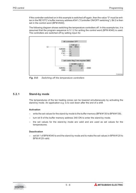
If the controller switched on in this example is switched off again, then the value “0“ must be written<br />
in the <strong>RE10TC</strong>’s buffer memory address #341 (“<strong>Control</strong>ler ON/OFF switching“). Bit 2 is then<br />
set in the control word (BFM #340).<br />
The following diagram shows switching the temperature controllers off. In this example too, it is<br />
assumed that the program sequence in 5.1.2 for writing the control word (BFM #340) is used.<br />
The controllers are switched off by setting input X2.<br />
Fig. 5-5: Switching off the temperature controllers<br />
5.2.1 Stand-by mode<br />
TC00034b<br />
The temperatures of the ten heating zones can be lowered simultaneously by activating the<br />
stand-by mode. An application e.g. is to cool down after the end of a shift.<br />
Activation<br />
– write the set values for the stand-by mode to the buffer memory (BFM #130 to BFM #139).<br />
– turn bit 9 of the buffer memory address 340 ON to enter the stand-by mode.<br />
– the set values for the stand-by mode are valid and are used as set values for the<br />
temperatures.<br />
Deactivation<br />
– set bit 1 of BFM #340 to end the stand-by mode and to make the set values in BFM #120 to<br />
BFM #129 valid.<br />
5-6 MITSUBISHI ELECTRIC