RE10TC Temperature Control Module Operating manual
RE10TC Temperature Control Module Operating manual
RE10TC Temperature Control Module Operating manual

You also want an ePaper? Increase the reach of your titles
YUMPU automatically turns print PDFs into web optimized ePapers that Google loves.
Installation Wiring<br />
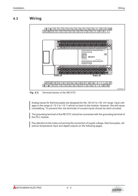
4.3 Wiring<br />
TC0+ TC1+ TC2+ TC3+ TC4+ TC5+ TC6+ TC7+ TC8+ TC9+ CT+ URT+ IRT+ AGND<br />
+24V GND TC0- TC1- TC2- TC3- TC4- TC5- TC6- TC7- TC8- TC9- CT- URT- IRT-<br />
Analog inputs for thermocouples are designed for the -30 mV to +30 mV range. Input voltages<br />
in the range of -15 V to +15 V will do no harm to the module. However, this will cause<br />
crosstalking. To prevend this, the terminals of unused inputs should be short-circuited.<br />
The grounding terminal of the <strong>RE10TC</strong> should be connected with the grounding terminal of<br />
the PLC module.<br />
Pay attention to the notes concerning the connection of supply voltage, thermocouples, reference<br />
temperature input and digital outputs on the following pages.<br />
MITSUBISHI ELECTRIC 4 - 3<br />
TC0+ TC1+ TC2+ TC3+ TC4+ TC5+ TC6+ TC7+ TC8+ TC9+ CT+ URT+ IRT+ AGND<br />
+24V GND TC0- TC1- TC2- TC3- TC4- TC5- TC6- TC7- TC8- TC9- CT- URT- IRT-<br />
<strong>RE10TC</strong><br />
Heating Output Cooling Output<br />
8 9 0<br />
8 9 0<br />
Cooling Output Y - Output<br />
+24VY COM YH0 YH1 YH2 YH3 YH4 YH5 YH6 YH7 YH8 YH9 Y0 Y1 +12V VPP<br />
YC0 YC1 YC2 YC3 YC4 YC5 YC6 YC7 YC8 YC9 Y2 Y3 GND GND<br />
+24VY COM YH0 YH1 YH2 YH3 YH4 YH5 YH6 YH7 YH8 YH9 Y0 Y1 +12V VPP<br />
YC0 YC1 YC2 YC3 YC4 YC5 YC6 YC7 YC8 YC9 Y2 Y3 GND GND<br />
Fig. 4-3: Terminal blocks of the <strong>RE10TC</strong><br />
2<br />
Loop<br />
POWER<br />
TC00003C