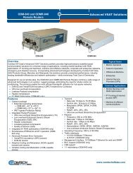
RSU-503 Redundancy Switch Unit Installation ... - Comtech EF Data
RSU-503 Redundancy Switch Unit Installation ... - Comtech EF Data
RSU-503 Redundancy Switch Unit Installation ... - Comtech EF Data

You also want an ePaper? Increase the reach of your titles
YUMPU automatically turns print PDFs into web optimized ePapers that Google loves.
3.1 Power<br />
3Chapter 3.<br />
THEORY OF OPERATION<br />
This chapter provides the basic theory for the following:<br />
• <strong>Switch</strong> power<br />
• Waveguide and coax switch drivers<br />
• LNA<br />
• M&C operational control<br />
In a redundant system, the switch is powered from either of the two RFT terminals via<br />
the M&C interconnect cable. External DC power (approximately 10.8V) enters the M&C<br />
on pins 1 and 2 of connector J17 (25-pin D), and is “ORed” through diodes CR1 and<br />
CR2.<br />
The switch is monitored by the analog-to-digital (A/D) converter U16, and is made<br />
available as a maintenance status through the serial terminal.<br />
A 3-terminal regulator, U1, converts and regulates the +5V to all the logic, including the<br />
microcontroller U18.<br />
PS1 converts the 10V input voltage to 30V, where it is stored by capacitors C6 through<br />
C10 to supply the 500 millisecond pulses to the transfer switches.<br />
Rev. 8 3–1