RSU-503 Redundancy Switch Unit Installation ... - Comtech EF Data
RSU-503 Redundancy Switch Unit Installation ... - Comtech EF Data
RSU-503 Redundancy Switch Unit Installation ... - Comtech EF Data

You also want an ePaper? Increase the reach of your titles
YUMPU automatically turns print PDFs into web optimized ePapers that Google loves.
Theory of Operation <strong>RSU</strong>-<strong>503</strong> <strong>Redundancy</strong> <strong>Switch</strong> <strong>Unit</strong><br />
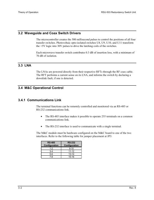
3.2 Waveguide and Coax <strong>Switch</strong> Drivers<br />
3.3 LNA<br />
The microcontroller creates the 500 millisecond pulses to control the positions of all four<br />
transfer switches. Photovoltaic opto-isolated switches U8, U9, U10, and U11 transform<br />
the +5V logic into 30V pulses to drive the latching coils of the switches.<br />
Each microwave transfer switch contributes 0.3 dB of insertion loss, with a minimum of<br />
70 dB of isolation.<br />
The LNAs are powered directly from their respective RFTs through the RF coax cable.<br />
The RFT performs a current sense on its LNA, and informs the switch by declaring a<br />
downlink fault, if one is detected.<br />
3.4 M&C Operational Control<br />
3.4.1 Communications Link<br />
The terminal functions can be remotely controlled and monitored via an RS-485 or<br />
RS-232 communications link.<br />
• The RS-485 interface makes it possible to operate 255 terminals on a common<br />
communications link.<br />
• The RS-232 interface is used to communicate with a single terminal.<br />
The M&C module must be hardware configured on the M&C board to one of the two<br />
interfaces. Refer to the following table for jumper placement at JP3:<br />
RS-485<br />
RS-232<br />
Configuration Configuration<br />
1-2 9-10<br />
3-4 11-12<br />
5-6 13-14<br />
7-8 15-16<br />
3–2 Rev. 8