RSU-503 Redundancy Switch Unit Installation ... - Comtech EF Data
RSU-503 Redundancy Switch Unit Installation ... - Comtech EF Data
RSU-503 Redundancy Switch Unit Installation ... - Comtech EF Data

You also want an ePaper? Increase the reach of your titles
YUMPU automatically turns print PDFs into web optimized ePapers that Google loves.
Maintenance <strong>RSU</strong>-<strong>503</strong> <strong>Redundancy</strong> <strong>Switch</strong> <strong>Unit</strong><br />
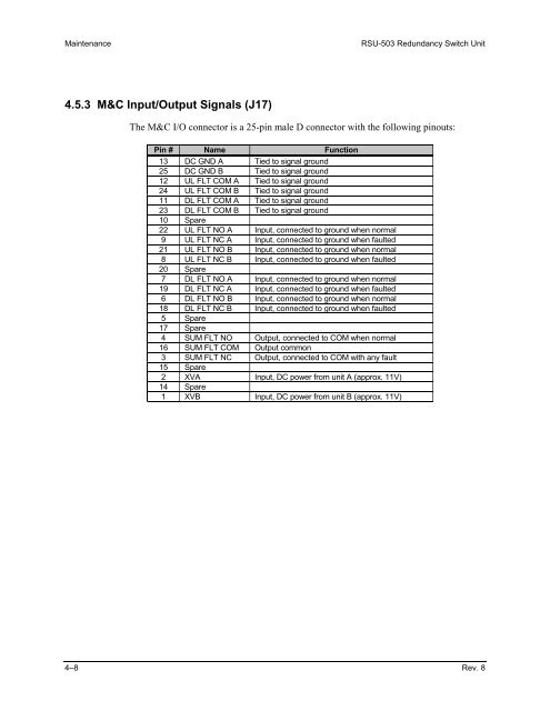
4.5.3 M&C Input/Output Signals (J17)<br />
The M&C I/O connector is a 25-pin male D connector with the following pinouts:<br />
Pin # Name Function<br />
13 DC GND A Tied to signal ground<br />
25 DC GND B Tied to signal ground<br />
12 UL FLT COM A Tied to signal ground<br />
24 UL FLT COM B Tied to signal ground<br />
11 DL FLT COM A Tied to signal ground<br />
23 DL FLT COM B Tied to signal ground<br />
10 Spare<br />
22 UL FLT NO A Input, connected to ground when normal<br />
9 UL FLT NC A Input, connected to ground when faulted<br />
21 UL FLT NO B Input, connected to ground when normal<br />
8 UL FLT NC B Input, connected to ground when faulted<br />
20 Spare<br />
7 DL FLT NO A Input, connected to ground when normal<br />
19 DL FLT NC A Input, connected to ground when faulted<br />
6 DL FLT NO B Input, connected to ground when normal<br />
18 DL FLT NC B Input, connected to ground when faulted<br />
5 Spare<br />
17 Spare<br />
4 SUM FLT NO Output, connected to COM when normal<br />
16 SUM FLT COM Output common<br />
3 SUM FLT NC Output, connected to COM with any fault<br />
15 Spare<br />
2 XVA Input, DC power from unit A (approx. 11V)<br />
14 Spare<br />
1 XVB Input, DC power from unit B (approx. 11V)<br />
4–8 Rev. 8