

165-GHz Transceiver in SiGe Technology - Computer Engineering ...
165-GHz Transceiver in SiGe Technology - Computer Engineering ...
165-GHz Transceiver in SiGe Technology - Computer Engineering ...

You also want an ePaper? Increase the reach of your titles
YUMPU automatically turns print PDFs into web optimized ePapers that Google loves.
LASKIN et al.: <strong>165</strong>-GHZ TRANSCEIVER IN SIGE TECHNOLOGY 1089<br />
Fig. 5. (a) Block diagram and port def<strong>in</strong>itions for a quadruple-push oscillator.<br />
(b) Equivalent circuit for one of the sub-oscillators.<br />
TABLE I<br />
EIGENVECTORS AND EIGENVALUES FOR EACH OSCILLATION MODE<br />
“even mode” and “common mode” are used <strong>in</strong>terchangeably to<br />
mean the same th<strong>in</strong>g. Similarly, “odd mode” and “differential<br />
mode” refer to the same circuit condition.<br />
To start the analysis, the oscillator is represented as the fourport<br />
circuit of Fig. 5(a). Each of the four Colpitts circuits, <strong>in</strong>clud<strong>in</strong>g<br />
their common-mode resistors, is modeled as a separate<br />
sub-oscillator. All four sub-oscillators are coupled with a network<br />
that consists of transmission l<strong>in</strong>es and a load resistor .<br />
The voltage, current, and impedance phasors of the 4-push oscillator<br />
topology are related by the follow<strong>in</strong>g matrix equation:<br />
. Tak<strong>in</strong>g <strong>in</strong>to account the symmetries that exist <strong>in</strong><br />
the circuit, i.e., for and<br />
, the matrix equation can be recast as<br />
The eigenvectors and eigenvalues of (1) represent all the oscillation<br />
modes of the circuit. The eigenvalues and eigenvectors<br />
obta<strong>in</strong>ed by solv<strong>in</strong>g (1) are given <strong>in</strong> Table I. In each oscillation<br />
mode (i.e., even, odd, or quadrature), the phases and relative amplitudes<br />
of the signals produced by the sub-oscillators are represented<br />
by the elements of the eigenvector that describes that<br />
mode. For example, the values of and <strong>in</strong> the<br />
odd mode, illustrate that sub-oscillators 1 and 2 produce signals<br />
of equal amplitude which are 180 out of phase. The impedance<br />
seen at the ports of the oscillator <strong>in</strong> a particular mode is given<br />
by the eigenvalue correspond<strong>in</strong>g to that mode.<br />
The quadrature oscillation mode is described by two eigenvectors<br />
which satisfy the equation and, at<br />
(1)<br />
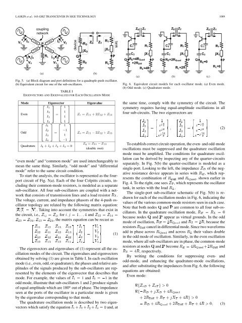
Fig. 6. Equivalent circuit models for each oscillator mode. (a) Even mode.<br />
(b) Odd mode. (c) Quadrature mode.<br />
the same time, comply with the symmetry of the circuit. The<br />
symmetry requires hav<strong>in</strong>g equal-amplitude oscillations <strong>in</strong> all<br />
four sub-circuits. The two eigenvectors are<br />
To establish correct circuit operation, the even- and odd-mode<br />
oscillations must be suppressed and the quadrature oscillation<br />
mode must be amplified. The conditions for quadrature oscillation<br />
can be derived by <strong>in</strong>spect<strong>in</strong>g any of the quarter-circuits<br />
separately. In Fig. 5(b) the quarter-oscillator is modeled as a<br />
s<strong>in</strong>gle-port. Look<strong>in</strong>g to the left, the impedance of the negative<br />
resistance device appears <strong>in</strong> series with , which represents<br />
the comb<strong>in</strong>ation of and , shown earlier <strong>in</strong><br />
Fig. 4. To the right, one sees , which represents the oscillator<br />
tank, <strong>in</strong> series with the load .<br />
The s<strong>in</strong>gle-port sub-oscillator schematic of Fig. 5(b) is redrawn<br />
for each of the oscillation modes <strong>in</strong> Fig. 6, <strong>in</strong>dicat<strong>in</strong>g the<br />
values of the various common-mode resistors seen <strong>in</strong> each case.<br />
Note that both nodes and are common to all four sub-oscillators.<br />
In the quadrature oscillation mode,<br />
because nodes and appear as virtual grounds. In the odd<br />
mode of oscillation, and , because the<br />
resistors cancel <strong>in</strong> differential mode. S<strong>in</strong>ce two waveforms<br />
add <strong>in</strong> phase across and across their values double<br />
<strong>in</strong> the odd mode of oscillation. Similarly, <strong>in</strong> the even oscillation<br />
mode, where all sub-oscillators are <strong>in</strong> phase, the common-mode<br />
resistors at nodes and become and<br />
, respectively.<br />
By writ<strong>in</strong>g the conditions for suppress<strong>in</strong>g even- and<br />
odd-mode, and enhanc<strong>in</strong>g the quadrature-mode oscillations,<br />
and after substitut<strong>in</strong>g the impedances from Fig. 6, the follow<strong>in</strong>g<br />
equations are obta<strong>in</strong>ed:<br />
Even mode:<br />
(2)<br />
(3)


