

165-GHz Transceiver in SiGe Technology - Computer Engineering ...
165-GHz Transceiver in SiGe Technology - Computer Engineering ...
165-GHz Transceiver in SiGe Technology - Computer Engineering ...

Create successful ePaper yourself
Turn your PDF publications into a flip-book with our unique Google optimized e-Paper software.
LASKIN et al.: <strong>165</strong>-GHZ TRANSCEIVER IN SIGE TECHNOLOGY 1091<br />
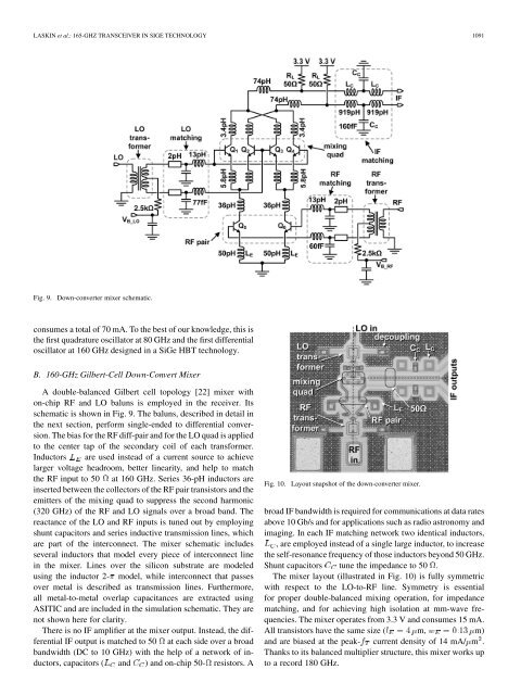
Fig. 9. Down-converter mixer schematic.<br />
consumes a total of 70 mA. To the best of our knowledge, this is<br />
the first quadrature oscillator at 80 <strong>GHz</strong> and the first differential<br />
oscillator at 160 <strong>GHz</strong> designed <strong>in</strong> a <strong>SiGe</strong> HBT technology.<br />
B. 160-<strong>GHz</strong> Gilbert-Cell Down-Convert Mixer<br />
A double-balanced Gilbert cell topology [22] mixer with<br />
on-chip RF and LO baluns is employed <strong>in</strong> the receiver. Its<br />
schematic is shown <strong>in</strong> Fig. 9. The baluns, described <strong>in</strong> detail <strong>in</strong><br />
the next section, perform s<strong>in</strong>gle-ended to differential conversion.<br />
The bias for the RF diff-pair and for the LO quad is applied<br />
to the center tap of the secondary coil of each transformer.<br />
Inductors are used <strong>in</strong>stead of a current source to achieve<br />
larger voltage headroom, better l<strong>in</strong>earity, and help to match<br />
the RF <strong>in</strong>put to 50 at 160 <strong>GHz</strong>. Series 36-pH <strong>in</strong>ductors are<br />
<strong>in</strong>serted between the collectors of the RF pair transistors and the<br />
emitters of the mix<strong>in</strong>g quad to suppress the second harmonic<br />
(320 <strong>GHz</strong>) of the RF and LO signals over a broad band. The<br />
reactance of the LO and RF <strong>in</strong>puts is tuned out by employ<strong>in</strong>g<br />
shunt capacitors and series <strong>in</strong>ductive transmission l<strong>in</strong>es, which<br />
are part of the <strong>in</strong>terconnect. The mixer schematic <strong>in</strong>cludes<br />
several <strong>in</strong>ductors that model every piece of <strong>in</strong>terconnect l<strong>in</strong>e<br />
<strong>in</strong> the mixer. L<strong>in</strong>es over the silicon substrate are modeled<br />
us<strong>in</strong>g the <strong>in</strong>ductor 2- model, while <strong>in</strong>terconnect that passes<br />
over metal is described as transmission l<strong>in</strong>es. Furthermore,<br />
all metal-to-metal overlap capacitances are extracted us<strong>in</strong>g<br />
ASITIC and are <strong>in</strong>cluded <strong>in</strong> the simulation schematic. They are<br />
not shown here for clarity.<br />
There is no IF amplifier at the mixer output. Instead, the differential<br />
IF output is matched to 50 at each side over a broad<br />
bandwidth (DC to 10 <strong>GHz</strong>) with the help of a network of <strong>in</strong>ductors,<br />
capacitors ( and ) and on-chip 50- resistors. A<br />
Fig. 10. Layout snapshot of the down-converter mixer.<br />
broad IF bandwidth is required for communications at data rates<br />
above 10 Gb/s and for applications such as radio astronomy and<br />
imag<strong>in</strong>g. In each IF match<strong>in</strong>g network two identical <strong>in</strong>ductors,<br />
, are employed <strong>in</strong>stead of a s<strong>in</strong>gle large <strong>in</strong>ductor, to <strong>in</strong>crease<br />
the self-resonance frequency of those <strong>in</strong>ductors beyond 50 <strong>GHz</strong>.<br />
Shunt capacitors tune the impedance to 50 .<br />
The mixer layout (illustrated <strong>in</strong> Fig. 10) is fully symmetric<br />
with respect to the LO-to-RF l<strong>in</strong>e. Symmetry is essential<br />
for proper double-balanced mix<strong>in</strong>g operation, for impedance<br />
match<strong>in</strong>g, and for achiev<strong>in</strong>g high isolation at mm-wave frequencies.<br />
The mixer operates from 3.3 V and consumes 15 mA.<br />
All transistors have the same size ( m, m)<br />
and are biased at the peak- current density of 14 mA/ m .<br />
Thanks to its balanced multiplier structure, this mixer works up<br />
to a record 180 <strong>GHz</strong>.


