

165-GHz Transceiver in SiGe Technology - Computer Engineering ...
165-GHz Transceiver in SiGe Technology - Computer Engineering ...
165-GHz Transceiver in SiGe Technology - Computer Engineering ...

You also want an ePaper? Increase the reach of your titles
YUMPU automatically turns print PDFs into web optimized ePapers that Google loves.
1090 IEEE JOURNAL OF SOLID-STATE CIRCUITS, VOL. 43, NO. 5, MAY 2008<br />
Fig. 7. Quadrature oscillator schematic.<br />
Odd mode:<br />
Quadrature mode:<br />
F<strong>in</strong>ally, (7) describes the quadrature oscillation condition and<br />
is obta<strong>in</strong>ed from <strong>in</strong>equalities (3), (4), and (5) and from (6), where<br />
is the negative resistance of the active device.<br />
It should be noted that, although the roles of and<br />
are not immediately apparent from the model of Fig. 5(a), they<br />
are critical <strong>in</strong> determ<strong>in</strong><strong>in</strong>g the phases of the oscillator outputs<br />
<strong>in</strong> a circuit implementation. S<strong>in</strong>ce the order of the entries of<br />
the quadrature-mode eigenvectors of (2) can be <strong>in</strong>terchanged<br />
without affect<strong>in</strong>g the solution, and are responsible<br />
for establish<strong>in</strong>g the exact phase relationships of the four outputs<br />
(i.e., which output is 0 , which is 90 , etc.). Furthermore,<br />
and help with suppress<strong>in</strong>g the odd and even oscillation<br />
modes by significantly degrad<strong>in</strong>g the of the capacitor <strong>in</strong><br />
Fig. 6(a) and (b).<br />
(4)<br />
(5)<br />
(6)<br />
(7)<br />
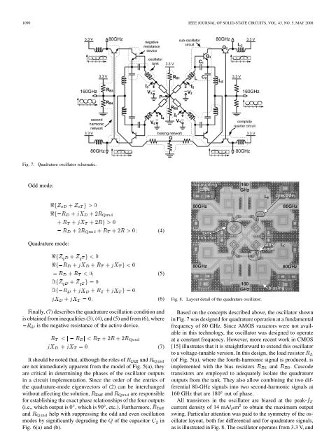
Fig. 8. Layout detail of the quadrature oscillator.<br />
Based on the concepts described above, the oscillator shown<br />
<strong>in</strong> Fig. 7 was designed for quadrature operation at a fundamental<br />
frequency of 80 <strong>GHz</strong>. S<strong>in</strong>ce AMOS varactors were not available<br />
<strong>in</strong> this technology, the oscillator was designed to operate<br />
at a constant frequency. However, more recent work <strong>in</strong> CMOS<br />
[15] illustrates that it is straightforward to extend this oscillator<br />
to a voltage-tunable version. In this design, the load resistor<br />
(of Fig. 5(a), where the fourth-harmonic signal is produced, is<br />
implemented with the bias resistors and . Cascode<br />
transistors are employed to adequately isolate the quadrature<br />
outputs from the tank. They also allow comb<strong>in</strong><strong>in</strong>g the two differential<br />
80-<strong>GHz</strong> signals <strong>in</strong>to two second-harmonic signals at<br />
160 <strong>GHz</strong> that are 180 out of phase.<br />
All transistors <strong>in</strong> the oscillator are biased at the peakcurrent<br />
density of 14 mA/ m to obta<strong>in</strong> the maximum output<br />
sw<strong>in</strong>g. Particular attention was paid to the symmetry of the oscillator<br />
layout, both for differential and for quadrature signals,<br />
as is illustrated <strong>in</strong> Fig. 8. The oscillator operates from 3.3 V, and


